

 Download PDF
BL0100A SANKEN
Document overview
- PDF pages: 19
Technical content
Page 1
High Efficiency For LED Backlight, 1ch LED Driver IC
General Descriptions BL0100A is LED driver IC for LED backlight, and it can do dimming to 0.02 % by external PWM signal. This IC realizes a high efficiency by the boost convertor control that absorbs variability on VF. The product easily achieves high cost-performance LED drive system with few external components and enhanced protection functions.
Features and Benefit Boost convertor
- Current-Mode type PWM Control
- PWM frequency is 100 kHz to 500kHz
- Maximum On Duty is 90 % LED current control
- PWM Dimming
- Analog Dimming
- High contrast ratio is 1 / 5000
- Accuracy of Reg output voltage is ± 2 % Protection functions
- Error Signal Output
- Overcurrent Protection for Boost Circuit (OCP) ------------------------------------------------- Pulse-by-pulse
- Overcurrent Protection for LED Output (LED_OCP) ------------------------------------------------- Pulse-by-pulse
- Overvoltage Protection (OVP) -------------- Auto restart
- Output Open/Short Protection --------------- Auto restart
- Thermal Shutdown (TSD) -------------------- Auto restart
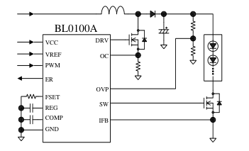
Typical Application Circuit
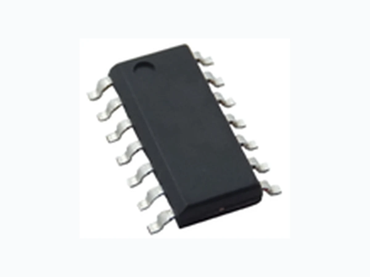
Package SOIC14
Not to scale
Electrical Characteristics
Absolute maximum voltage of VCC pin is 20 V Adjustable PWM frequency, 100 kHz to 500 kHz
Applications
LED backlights LED lighting etc.
Page 2
CONTENTS
General Descriptions ----------------------------------------------------------------------- 1 1. Absolute Maximum Ratings --------------------------------------------------------- 3 2. Electrical characteristics ------------------------------------------------------------- 3 3. Functional Block Diagram ----------------------------------------------------------- 5 4. Pin List Table --------------------------------------------------------------------------- 5 5. Typical Application Circuit --------------------------------------------------------- 6 6. Package Diagram ---------------------------------------------------------------------- 7 7. Marking Diagram --------------------------------------------------------------------- 7
- Functional Description --------------------------------------------------------------- 8 8.1 Startup Operation ------------------------------------------------------------ 8 8.2 Constant Current Control Operation ------------------------------------ 9 8.3 PWM Dimming Function --------------------------------------------------- 9 8.4 Gate Drive ---------------------------------------------------------------------- 9 8.5 Protection Function --------------------------------------------------------- 10 8.6 Error Signal Output Function -------------------------------------------- 13 9. Design Notes --------------------------------------------------------------------------- 14
9.1 Peripheral Components ---------------------------------------------------- 14 9.2 Inductor Design Parameters----------------------------------------------- 14 9.3 PCD Trace Layout and Component Placement ----------------------- 14 10. Reference Design of Power Supply ----------------------------------------------- 16
OPERATING PRECAUTIONS -------------------------------------------------------- 18
IMPORTANT NOTES ------------------------------------------------------------------- 19
Page 3
1. Absolute Maximum Ratings
The polarity value for current specifies a sink as "+," and a source as "−," referencing the IC. Unless otherwise specified, TA is 25 °C
| Parameter | Symbol | Test Conditions | Pins | Rating | Unit |
|---|---|---|---|---|---|
| REG Pin Source Current | I REG | 2−7 | − 1 | mA | |
| OVP Pin Voltage | V OVP | 3−7 | − 0.3~5 | V | |
| PWM Pin Voltage | V PWM | 4−7 | − 0.3~5 | V | |
| IFB Pin Clamp Current | I FB | Single pulse 5 µs | 12−7 | − 10 | mA |
| FSET Pin Source Current | I FSET | 6−7 | − 300 | µA | |
| VCC Pin Voltage | V CC | 8−7 | − 0.3~20 | V | |
| SW Pin Voltage | V SW | 9−7 | − 0.3~V + 0.3 CC | V | |
| DRV Pin Voltage | V DRV | 10−7 | − 0.3~V + 0.3 CC | V | |
| OC Pin Voltage | V OC | 11−7 | − 0.3~5 | V | |
| ER Pin Voltage | V ER | 14−7 | − 0.3~V RE G | V | |
| VREF Pin Voltage | V REF | 1−7 | − 0.3~5 | V | |
| Operating Ambient Temperature | T op | − | − 40~85 | °C | |
| Storage Temperature | T stg | − | − 40~125 | °C | |
| Junction Temperature | T j | − | 150 | °C |
2. Electrical characteristics
The polarity value for current specifies a sink as "+," and a source as "−," referencing the IC. Unless otherwise specified, TA is 25 °C, VCC = 12 V
| Parameter | Symbol | Test Conditions | Pins | Min. | Typ. | Max. | Unit |
|---|---|---|---|---|---|---|---|
| Start / Stop Operation | |||||||
| Operation Start Voltage1 | V CC(ON) | 8−7 | 8.5 | 9.6 | 10.5 | V | |
| Operation Stop Voltage | V CC(OFF) | 8−7 | 8.0 | 9.1 | 10.0 | V | |
| Circuit Current in Operation | I CC(ON) | 8−7 | − | 5.3 | 8.0 | mA | |
| Circuit Current in Non-Operation | I CC(OFF) | V = 8 V CC | 8−7 | − | 70 | 200 | µA |
| REG Pin Output Voltage | V REG | 2−7 | 4.9 | 5.0 | 5.1 | V | |
| Oscillation | |||||||
| PWM Operation Frequency 1 | f PWM1 | V = 2 V FSET | 10−7 | 95 | 100 | 105 | kHz |
| PWM Operation Frequency 2 | f PWM2 | R22= 4.7 kΩ | 10−7 | 440 | 500 | 560 | kHz |
| Maximum ON Duty | D MAX | 10−7 | 85 | 90 | 95 | % | |
| Minimum ON Time | t MIN | 10−7 | 40 | 140 | 240 | ns | |
| COMP Pin Voltage at Oscillation Start | V COMP(ON) | 13−7 | 0.35 | 0.50 | 0.65 | V | |
| COMP Pin Voltage at Oscillation Stop | V COMP(OFF) | 13−7 | 0.10 | 0.25 | 0.40 | V | |
| VREF / IFB Pin | |||||||
| VREF Pin Minimum Setting Voltage | V REF(MIN) | V = 0 V REF | 1−7 | 0.05 | 0.25 | 0.45 | V |
| VREF Pin Maximum Setting Voltage | V REF(MAX) | V = 5 V REF | 1−7 | 1.75 | 2.00 | 2.35 | V |
1 VCC(ON) > VCC(OFF)
Page 4
| Parameter | Symbol | Test Conditions | Pins | Min. | Typ. | Max. | Unit |
|---|---|---|---|---|---|---|---|
| IFB Pin Voltage at Auto Restart Operation | V IFB(AR) | V = 1 V REF | 12−7 | 0.45 | 0.50 | 0.55 | V |
| IFB Pin Voltage at COMP Charge Switching | V IFB(COMP) | V = 1 V REF | 12−7 | 0.55 | 0.60 | 0.65 | V |
| IFB Pin Overcurrent Protection Low Threshold Voltage | V IFB(OCL) | V = 1 V REF | 12−7 | 1.9 | 2.0 | 2.1 | V |
| IFB Pin Overcurrent Protection Release Threshold Voltage | V IFB(OCL-OFF) | V = 1 V REF | 12−7 | 1.5 | 1.6 | 1.7 | V |
| IFB Pin Overcurrent Protection High Threshold Voltage | V IFB(OCH) | 12−7 | 3.8 | 4.0 | 4.2 | V | |
| IFB Pin Bias Current | I IFB(B) | V = 5 V IFB | 12−7 | − | − | 1 | µA |
| Current Detection Threshold Voltage | V IFB | V = 1 V REF | 12−7 | 0.98 | 1.00 | 1.02 | V |
| COMP Pin | |||||||
| COMP Pin Maximum Output Voltage | V COMP(MAX) | V = 0.7 V IFB | 13−7 | 4.8 | 5.0 | − | V |
| COMP Pin Minimum Output Voltage | V COMP(MIN) | V = 2.0 V IFB | 13−7 | − | 0 | 0.2 | V |
| Transconductance | gm | − | − | 640 | − | µS | |
| COMP Pin Source Current | I COMP(SRC) | V = 0.7 V IFB | 13−7 | − 77 | − 57 | − 37 | µA |
| COMP Pin Sink Current | I COMP(SNK) | V = 1.5 V IFB | 13−7 | 37 | 57 | 77 | µA |
| COMP Pin Charge Current at Startup | I COMP(S) | V = 0 V COMP | 13−7 | − 19 | − 11 | − 3 | µA |
| COMP Pin Reset Current | I COMP(R) | 13−7 | 200 | 360 | 520 | µA | |
| ER Pin | |||||||
| ER Pin Sink Current during Non-Alarm | I ER | V = 1 V ER | 14−7 | 2.5 | 4.4 | 6.3 | mA |
| Boost Parts Overcurrent Protection (OCP) | |||||||
| OC Pin Overcurrent Protection Threshold Voltage | V OCP | V = 4.5 V COMP | 11−7 | 0.57 | 0.60 | 0.63 | V |
| Overvoltage Protection (OVP) | |||||||
| OVP Pin Overvoltage Protection Threshold Voltage | V OVP | 3−7 | 2.85 | 3.00 | 3.15 | V | |
| OVP Pin OVP Release Threshold Voltage | V OVP(OFF) | 3−7 | 2.60 | 2.75 | 2.90 | V | |
| PWM Pin | |||||||
| PWM Pin ON Threshold Voltage | V PWM(ON) | 4−7 | 1.4 | 1.5 | 1.6 | V | |
| PWM Pin OFF Threshold Voltage | V PWM(OFF) | 4−7 | 0.9 | 1.0 | 1.1 | V | |
| PWM Pin Impedance | R PWM | 4−7 | 100 | 200 | 300 | kΩ | |
| SW / DRV Pin | |||||||
| SW Pin Source Current | I SW(SRC) | 9−7 | − | − 85 | − | mA | |
| SW Pin Sink Current | I SW(SNK) | 9−7 | − | 220 | − | mA | |
| DRV Pin Source Current | I DRV(SRC) | 10−7 | − | − 0.36 | − | A | |
| DRV Pin Sink Current | I DRV(SNK) | 10−7 | − | 0.85 | − | A | |
| Thermal Shutdown Protection (TSD) | |||||||
| Thermal Shutdown Activating Temperature | T j(TSD) | − | 125 | − | − | °C | |
| Hysteresis Temperature of TSD | T j(TSD)HYS | − | − | 65 | − | °C | |
| Thermal Resistance | |||||||
| Thermal Resistance from Junction to Ambient | θj-A | − | − | − | 120 | °C/W | |
Page 5
3. Functional Block Diagram
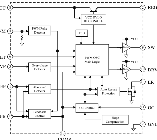
VCC
PWM
FSET
OVP
VREF
COMP
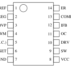
4. Pin List Table
| Number | Name | Function |
| 1 | VREF | Detection voltage setting |
| 2 | REG | Internal regulator output |
| 3 | OVP | Overvoltage detection signal input |
| 4 | PWM | Dimming MOSFET gate drive output |
| 5 | (N.C.) | - |
| 6 | FSET | Boost MOSFET drive frequency setting |
| 7 | GND | Ground |
| 8 | VCC | Power supply voltage input |
| 9 | SW | PWM dimming drive output |
| 10 | DRV | Boost MOSFET gate drive output |
| 11 | OC | Current mode control signal input and overcurrent protection signal input |
| 12 | IFB | Feedback signal input of current detection |
| 13 | COMP | Phase compensation and soft-start setting |
| 14 | ER | Error signal output |
VREF
PWM
(N.C.)
Page 6
5. Typical Application Circuit
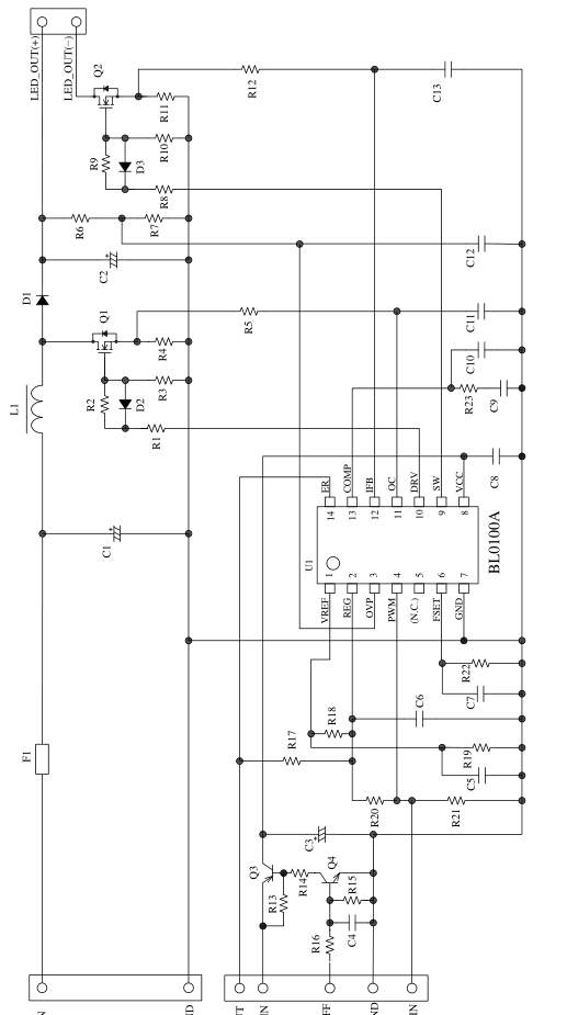
Figure 5-1 Typical Application Circuit
Page 7
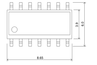
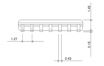
6. Package Diagram
SOIC14
0.6
NOTES:
1) Dimension is in millimeters
2) Pb-free. Device composition compliant with the RoHS directive
7. Marking Diagram
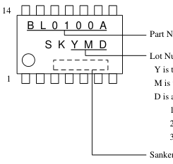
Part Number
Lot Number Y is the last digit of the year (0 to 9) M is the month (1 to 9, O, N or D) D is a period of days (1 to 3) : 1 : 1st to 10th 2 : 11th to 20th 3 : 21st to 31st
Sanken Control Number
Page 8
8. Functional Description
All of the parameter values used in these descriptions are typical values, unless they are specified as minimum or maximum. With regard to current direction, "+" indicates sink current (toward the IC) and "–" indicates source current (from the IC).
8.1 Startup Operation
Figure 8-1 shows the VCC pin peripheral circuit. The VCC pin is the power supply input for control circuit from the external power supply. When the VCC pin voltage increases to the Operation Start Voltage, VCC(ON) = 9.6 V, the control circuit starts operation. After that, when the PWM pin voltage exceeds the PWM Pin ON Threshold Voltage, VPWM(ON) of 1.5 V (less than absolute maximum voltage of 5 V), the COMP Pin Charge Current at Startup, ICOMP(S) = −11 µA, flows from the COMP pin. This charge current flows to capacitors at the COMP pin. When the COMP pin voltage increases to the COMP Pin Voltage at Oscillation Start, VCOMP(ON) = 0.50 V or more, the control circuit
starts switching operation. As shown in Figure 8-2, when the VCC pin voltage decreases to the Operation Stop Voltage, VCC(OFF) = 9.1 V, the control circuit stops operation, by the UVLO (Undervoltage Lockout) circuit, and reverts to the state before startup.
External power supply
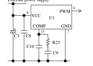
Figure 8-1 VCC pin peripheral circuit
ICC
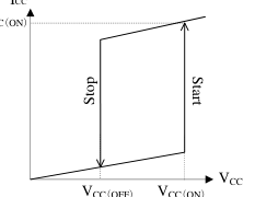
Figure 8-2 VCC versus ICC
When the on-duty of the PWM dimming signal is small, the charge current at the COMP pin is controlled as follows in order to raise the output current quickly at startup. Figure 8-3 shows the operation waveform with the PWM dimming signal at startup.
VCC pin voltage
VCC(ON)= 9.6V 0
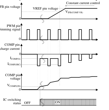
Figure 8-3 Startup operation during PWM dimming
While the IFB pin voltage increases to the IFB Pin Voltage at COMP Charge Switching, VIFB(COMP.VR), a capacitors at the COMP pin are charged by ICOMP(S) = –11 µA. During this period, they are charged by the COMP Pin Source Current, ICOMP(SRC) = –57 µA, when the PWM pin voltage is 1.5 V or more. Thus, the COMP pin voltage increases immediately. When the IFB pin voltage increases to VIFB(CMP1.VR) or more, the COMP pin source current is controlled according to the feedback amount, and the output current is controlled to be constant. The on-duty gradually becomes wide according to the increase of the COMP pin voltage, and the output power increases (Soft start operation). Thus, power
stresses on components are reduced. When the VCC pin voltage decreases to the operation stop voltage or less, or the Auto Restart operation (see the Section 8.5 Protection Function) after protection is achieved, then the control circuit stops switching operation, and capacitors at the COMP pin are discharged by the COMP Pin Reset Current, ICOMP(R) = 360 µA, simultaneously. The soft start operation is achieved at restart. The IC is operated by Auto Restart 1 at startup
Page 9
operation. See the Section 8.5 Protection Function about the caution of startup operation. VIFB(COMP.VR) is determined by the VREF pin voltage, as shown in Figure 8-4. When VREF pin voltage is 1V, the value of VIFB(COMP.VR) becomes 0.60 V.
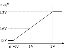
VIFB(COMP.VR)
VREF pin voltage
Figure 8-4 VREF pin voltage versus IFB pin voltage at
COMP charge switching
8.2 Constant Current Control Operation
Figure 8-5 shows the IFB pin peripheral circuit. When Q2 turns on, the LED output current, IOUT(CC), is detected by the current detection resistor, R11. The IC compares the IFB pin voltage with the VREF pin voltage by the internal error amplifier, and controls the IFB pin voltage so that it gets close to the VREF pin voltage. The reference voltage at the VREF pin is the divided voltage of the REG pin voltage, VREG = 5 V, by R20 and R21, and thus this voltage can be externally adjusted. The setting current, IOUT(CC), of the LED_OUT can be calculated as follows.
V I
(8-1)
REF OUT (CC) R SEN
where: VREF is the VREF pin voltage. The value is recommended to be 0.5 V to 2.0 V. RESN is the value of R11
U1
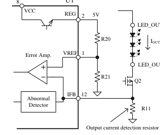
IOUT(CC)
Figure 8-5 IFB pin peripheral circuit
8.3 PWM Dimming Function
Figure 8-6 shows the peripheral circuit of PWM pin and SW pin. The PWM pin is used for the PWM dimming signal input. The SW pin drives the gate of external MOSFET, Q2. The SW pin voltage is turned on / off by PWM signal, and thus the dimming of LED is controlled by PWM signal input. As shown in Figure 8-7, when the PWM pin voltage becomes the PWM Pin ON Threshold Voltage, VPWM(ON) = 1.5 V or more, the SW pin voltage becomes VCC. When the PWM pin voltage becomes the PWM Pin OFF Threshold Voltage, VPWM(OFF) = 1.0 V or less, the SW pin voltage becomes 0.1 V or less. The PWM pin has the absolute maximum voltage of −0.3 V to 5.0 V, and the input impedance, RPWM, of 200 kΩ. The PWM
dimming signal should meet these specifications and threshold voltages of VPWM(ON) and VPWM(OFF).
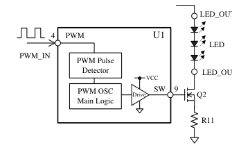
LED_OUT (−)
Figure 8-6 The peripheral circuit of PWM pin
and SW pin.
PWM pin voltage
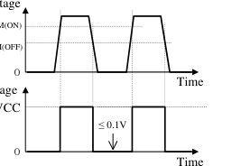
VPWM(ON) VPWM(OFF)
SW pin voltage
Figure 8-7 The waveform of PWM pin and SW pin
8.4 Gate Drive
Figure 8-8 shows the peripheral circuit of DRV pin and SW pin and FSET pin. The DRV pin is for boost MOSFET, Q1. The SW pin is for dimming MOSFET, Q2. Table 8-1 shows drive voltages and currents of DRV pin and SW pin.
- Q1 and Q2 should be selected so that these VGS(th) threshold voltages are less than VDRV enough over entire operating temperature range.
Page 10
- Peripheral components of Q1 (R1, R2, and D2) and Q2 (R8, R9, and D3) affect losses of power MOSFET, gate waveform (ringing caused by the printed circuit board trace layout), EMI noise, and so forth, these values should be adjusted based on actual operation in the application.
- R3 for Q1 and R10 for Q2 are used to prevent malfunctions due to steep dv/dt at turn-off of the power MOSFET, and these resistors are connected near each the gate of the power MOSFETs and the ground line side of the current detection resistance. The reference value of them is from 10 kΩ to 100 kΩ.
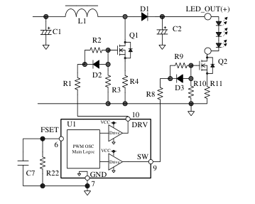
Figure 8-8 The peripheral circuit of DRV pin, SW pin and FSET pin
Table 8-1 Drive voltage and current
| Pins | Drive voltage, V DRV | Drive current, I DRV | ||
| High | Low | Source | Sink | |
| DRV | V CC | 0.1V or less | –0.36 A | 0.85 A |
| SW | V CC | 0.1V or less | –85 mA | 220 mA |
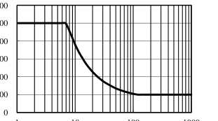
As shown in Figure 8-9, the PWM oscillation frequency of DRV pin can be set between 100 kHz and 500 kHz, depending on the value of R22 connected to FSET pin, RFSET. 600
1
10
100
1000
RFSET (kΩ)
Figure 8-9 Relation between PWM oscillation frequency
and RFSET
8.5 Protection Function
As shown in Table 8-2, the IC performs protection operations according to kind of abnormal state. In all protection functions, when the fault condition is removed, the IC returns to normal operation automatically. The intermitted oscillation operation reduces stress on the power MOSFET, the secondary rectifier diode, and so forth. Table 8-2 Relationship between a kind of abnormal state
and protection operations
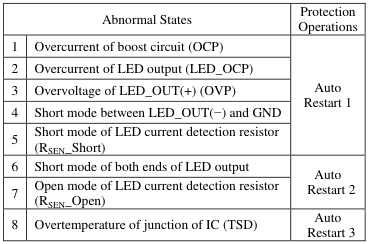
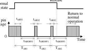
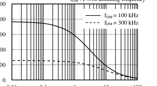
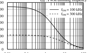
Auto Restart 1: As shown in Figure 8-10, the IC repeats an intermitted oscillation operation, after the detection of any one of abnormal states 1 to 5 in Table 8-2. This intermitted oscillation is determined by tARS1 or tARS2, and tAROFF1. The tARS1 is an oscillation time in the first intermitted oscillation cycle, TAR1. The tARS2 is an oscillation time in the second and subsequent intermitted oscillation cycle, TAR2. The tAROFF1 is a non-oscillation time in all intermitted oscillation cycle. In case PWM dimming frequency is low and the on-duty is small, the startup operation, the restart operation from on-duty = 0 % and the restart operation from intermitted oscillation operation need a long time.
Thus the value of tARS1 and tARS2 depend on frequency and on-duty of the PWM dimming signal, as shown in Figure 8-12 and Figure 8-13. In case the on-duty is 100 %, the value of tARS1 is 61.4 ms, and tARS2 is 41.0 ms. The value of tAROFF1 is about 1.3 s. Auto Restart 2: As shown in Figure 8-11, the IC stops the switching operation immediately after the detection of abnormal states 6 or 7 in Table 8-2, and repeats an intermitted oscillation operation. In the intermitted oscillation cycle, the tARSW is an oscillation time, the tAROFF1 is a non-oscillation time. The value of tARSW is a few microseconds. The value of tARS2 is derived from Figure 8-11, and tAROFF2 is
calculated as follows:
t t t 3.1(s)
(8-3)
AROFF ARS ARSW
Page 11
In case the on-duty is 100%, the value of tAROFF1 becomes about 1.341 ms. Auto Restart 3: The IC stops the switching operation immediately after the detection of abnormal states 8 in Table 8-2, and keeps a non-oscillation.
Release
Abnormal
SW pin voltage
Figure 8-10 Auto Restart 1
Release
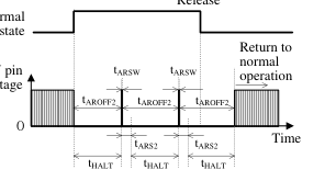
Abnormal
SW pin voltage
Figure 8-11 Auto Restart 2
fDM : PWM dimming frequency
2500
2000
1500
1000
0.01 0.1 1 10 100
Duty (%)
Figure 8-12 PWM dimming on-duty versus tARS1
fDM : PWM dimming frequency
1400
1200 1000
0.01 0.1 1 10 100
Duty (%)
Figure 8-13 PWM dimming on-duty versus tARS2
The operating condition of Auto Restart 1 and 2 is as follows: < The operating condition of Auto Restart 1 > The Auto Restart 1 is operated by the detection signals of the OC pin or IFB pin.
- Operation by the detection signal of OC pin: When the OC pin voltage increase to the OC Pin Overcurrent Protection Threshold Voltage, VOCP = 0.60 V, or more, the operation of the IC switches to Auto Restart 1. When the fault condition is removed and the OC pin voltage decreases to under VOCP, the IC returns to normal operation automatically.
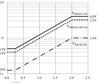
- Operation by the detection signal of IFB pin: As shown in Figure 8-14, IFB pin has two types of threshold voltage. These threshold voltages depend on the VREF pin voltage, as shown in Figure 8-15.
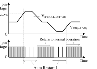
IFB pin voltage VIFB(OCL.VR)
SW pin voltage
Figure 8-14 IFB pin threshold voltage and Auto Restart 1 operation
VIFB(OCL.VR) : IFB Pin Overcurrent Protection Low Threshold Voltage VIFB(OCL-OFF.VR) :IFB Pin Overcurrent Protection Release Threshold Voltage VIFB(AR.VR) :IFB Pin Auto Restart Operation Threshold Voltage 10.0
0.125V
0.25V VREF pin voltage (V)
Figure 8-15 VREF pin voltage versus IFB pin threshold voltages
Page 12
1) In case IFB pin voltage increased When the FB pin voltage increase to VIFB(OCL.VR) in Figure 8-15, or more, the operation of the IC switches to Auto Restart 1. When the fault condition is removed and the IFB pin voltage decreases to VIFB(OCL-OFF.VR) in Figure 8-15, or less, the IC returns to normal operation automatically. 2) In case IFB pin voltage decreased When the FB pin voltage decrease to VIFB(AR.VR) in Figure 8-15, or more, the operation of the IC switches to Auto Restart 1. When the fault condition is removed and the IFB pin voltage increases to above VIFB(AR.VR), the IC returns to normal operation automatically. < The operating condition of Auto Restart 2 >
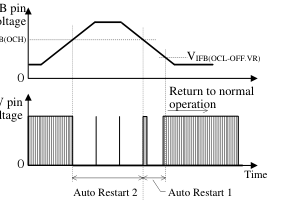
The Auto Restart 2 is operated by the detection signal of the IFB pin. As shown in Figure 8-16, when the FB pin voltage increase to the IFB Pin Overcurrent Protection High Threshold Voltage, VIFB(OCH) = 4.0 V, or more, the operation of the IC switches to Auto Restart 2, and the IC stops switching operation immediately. When the fault condition is removed and the IFB pin voltage decreases to under VIFB(OCH), the operation of the IC switches to Auto Restart 1.
VIFB(OCH)
SW pin voltage
Figure 8-16 IFB pin threshold voltage and Auto Restart 2 operation
< Caution of startup operation > When the LED current is low and the IFB pin voltage is less than VIFB(AR.BR), during startup for example, the IC is operated by Auto Restart 1. If the startup time is too long, the IC operation becomes the intermitted oscillation by the Auto Restart 1. It becomes cause of the fault startup operation, thus the startup time should be set less than tARS1 in Figure 8-10.
The protection operation according to the abnormal states in Table 8-2 is described in detail as follows:
8.5.1 Overcurrent of Boost Converter Part
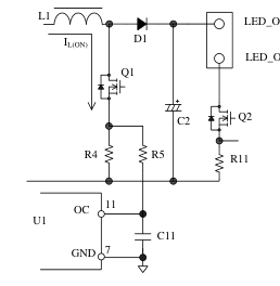
(OCP) When the OC pin detects the overcurrent of boost circuit, the IC switches to Auto Restart 1. Figure 8-17 shows the peripheral circuit of OC pin. When Q1 turns on, the current flowing to L1 is detected by R4, and the voltage on R4 is input to the OC pin. When the OC pin voltage increases to the OC Pin Overcurrent Protection Threshold Voltage, VOCP = 0.60 V or more, the on-duty becomes narrow by pulse-by-pulse basis, and the output power is limited.
LED_OUT(+)
LED_OUT(-)
Figure 8-17 OC pin peripheral circuit
8.5.2 Overcurrent of LED Output
(LED_OCP)
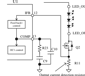
Figure 8-18 shows the peripheral circuit of IFB pin and COMP pin. When Q2 turns on, the output current is detected by R11. When the boost operation cannot be done by failure such as short circuits in LED string, the IFB pin voltage is increased by the increase of LED current. There are three types of operation modes in LED_OCP state. (1) When the IFB pin voltage is increased by the increase of LED current, COMP pin voltage is decreases. In addition, when the COMP pin voltage decreases to the COMP Pin Voltage at Oscillation Stop, VCOMP(OFF) = 0.25 V or less, the IC stops switching operation, and limits the increase of the output current. When IFB pin voltage is decreased by the decrease of
LED current, COMP pin voltage increases. When COMP pin voltage becomes VCOMP(ON) = 0.50 V or more, the IC restarts switching operation. (2) When IFB pin voltage becomes VIFB(OCL.VR) or more (see Figure 8-15), the IC switches to Auto Restart 1. (3) The LED current increases further and when the IFB pin voltage increases to the IFB Pin Overcurrent
Page 13
Protection High Threshold Voltage, VIFB(OCH) = 4.0 V or more, the IC switches to Auto Restart 2.
U1
LED_OUT(+)
LED_OUT(-)
Figure 8-18 The peripheral circuit of IFB pin
and COMP pin
8.5.3 Overvoltage of LED_OUT (+) (OVP)
Figure 8-19 shows OVP pin peripheral circuit. The OVP pin detects the divided LED output voltage by R6 and R7. When the LED_OUT (+) or the IFB pin is open and the OVP pin voltage increases to the OVP Pin Overvoltage Protection Threshold Voltage, VOVP = 3.00 V, the IC immediately stops switching operation. When the OVP pin voltage decreases to the OVP Pin Overvoltage Protection Release Threshold Voltage, VOVP(OFF) = 2.75 V or the IFB pin voltage decreases to VIFB(AR.VR) in Figure 8-15, then the IC switches to Auto Restart 1.
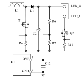
LED_OUT(+)
LED_OUT(-)
Figure 8-19 OVP pin peripheral circuit
8.5.4 Short Mode between LED_OUT(−)
and GND
When the LED_OUT (–) and the GND are shorted, and the IFB pin voltage decreases to VIFB(AR.VR) in Figure 8-15, then the IC switches to Auto Restart 1.
8.5.5 Short Mode of LED Current Detection
Resistor (RSEN_Short)
When the output current detection resistor, R11, is shorted, the IFB pin voltage decreases. When the IFB pin voltage decreases to VIFB(AR.VR) in Figure 8-15, then the IC switches to Auto Restart 1.
8.5.6 Short Mode of LED Output Both Ends
When the LED_OUT (+) and LED_OUT (–) are shorted, the short current flows through the detection resistor (R11) while Q2 turns on. The IFB pin detects the voltage rise of the detection resistor. When the IFB pin voltage increases to the IFB Pin Overcurrent Protection High Threshold Voltage, VIFB(OCH) = 4.0 V or more, the IC switches to Auto Restart 2.
8.5.7 Open Mode of LED Current Detection
Resistor (RSEN_Open)
When the output current detection resistor, R11, is open, the IFB pin voltage increases. When the IFB pin voltage increases to the IFB Pin Overcurrent Protection High Threshold Voltage, VIFB(OCH) = 4.0 V or more, the IC switches to Auto Restart 2.
8.5.8 Overtemperature of junction of IC
(TSD) When the temperature of the IC increases to Tj(TSD) = 125 °C (min) or more, the TSD is activated, and the IC stops switching operation. When the junction temperature decreases by Tj(TSD) − Tj(TSD)HYS after the fault condition is removed, the IC returns to normal operation automatically.
8.6 Error Signal Output Function
When the protection function is active, the internal switch becomes OFF. The drain of this internal switch is connected to ER pin. In case the error signal is received by external microcomputer, the pull-up resistor, R17, and the protection resistor of ER pin, RER, are connected as shown in Figure 8-20. When the protection function is active, ER_OUT becomes REG pin voltage from 0 V. The resistances of R17 and RER are about 10 kΩ.
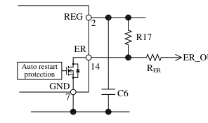
Figure 8-20 ER pin peripheral circuit
Page 14
9. Design Notes
9.1 Peripheral Components
Take care to use the proper rating and proper type of components. Input and output electrolytic capacitors, C1 and C2 ▫ Apply proper design margin to accommodate ripple current, voltage, and temperature rise. ▫ Use of high ripple current and low impedance types, designed for switch-mode power supplies, is recommended, depending on their purposes. Inductor,L1 ▫ Apply proper design margin to temperature rise by core loss and copper loss. ▫ Apply proper design margin to core saturation Current detection resistors, R4 and R11 Choose a type of low internal inductance because a high frequency switching current flows to the current detection resistor, and of properly allowable
dissipation.
9.2 Inductor Design Parameters
The CRM\* or DCM\* mode of boost converter with PWM dimming can improve the output current rise during PWM dimming. \* CRM is the critical conduction mode, DCM is the discontinuous conduction mode.
The CRM or DCM inductor design procedure is described as follow: (1) On-duty Setting The output voltage of boost converter is more than the input voltage. The on-duty, DON can be calculated using following equation. The equality of the equation means the condition of CRM mode operation and the inequality means that of DCM mode operation.
V V D OUT IN
(9-1)
ON V OUT
where: VIN is the minimum input voltage, VOUT is the maximum forward voltage drop of LED string. DON is selected by the above equation applied to CRM or DCM mode. In case fPWM = 100 kHz, the range of DON should be 1.4 % to 90 %. In case fPWM = 500 kHz, the range of DON should be 7 % to 90 %. (The minimum value results from the condition of tMIN = 140 ns, and fPWM. The maximum value is DMAX). (2) PWM oscillation frequency selection The PWM oscillation frequency of DRV pin, fPWM,
depends on the value of R22 connected to FSET pin. The value of fPWM is set by Figure 8-9. (3) Inductance value, L The inductance value, L, for DCM or CRM mode can be calculated as follow:
V D 2
L
IN ON
(9-2)
2 I f V V OUT PWM OUT IN
where: IOUT is the maximum output current, fPWM is the maximum operation frequency of PWM (4) Peak inductor current, ILP
V D I IN ON
(9-3)
LP L f PWM
(5) Inductor selection The inductor should be applied the value of inductance, L, from equation (9-2) and the DC superimposition characteristics being higher than the peak inductor current, ILP, from equation (9-3).
9.3 PCD Trace Layout and Component
Placement
Since the PCB circuit trace design and the component layout significantly affects operation, EMI noise, and power dissipation, the high frequency PCB trace as shown in Figure 9-1 should be low impedance with small loop and wide trace.
L1
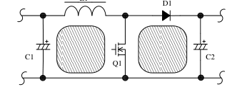
Figure 9-1 High-frequency current loops (hatched areas)
In addition, the ground traces affect radiated EMI noise, and wide, short traces should be taken into account. Figure 9-2 shows the circuit design example. (1) Main Circuit Trace Layout This is the main trace containing switching currents, and thus it should be as wide trace and small loop as possible. C1 should be connected near the inductors, L1, in order to reduce impedance of the high frequency current loop. (2) Control Ground Trace Layout Since the operation of IC may be affected from the large current of the main trace that flows in control ground trace, the control ground trace should be
Page 15
connected at a single point grounding of point A with a dedicated trace. (3) Current Detection Resistor Trace Layout R4 and R11 are current detection resistors. The trace from the base of current detection resistor should be connected to the pin of IC with a dedicated trace. (4) COMP pin Trace Layout for Compensation Component R23, C9 and C10 are compensation components. The trace of the compensation component should be connected as close as possible to the pin of IC, to reduce the influence of noise.
(5) Bypass Capacitor Trace Layout on VCC , REG, and VREF pins C8, C6 and C5 of bypass capacitors, connected to VCC, REG, and VREF pins respectively, should be connected as close as possible to the pin of IC (6) Power MOSFET Gate Trace Layout R3 for Q1 and R10 for Q2 should be connected near each the gate of the power MOSFETs and the ground line side of the current detection resistance. Peripheral components of Q1 (R1, R2, and D2) and Q2 (R8, R9, and D3) should be connected as close as possible between each the gate of the power MOSFETs and the pin of IC.
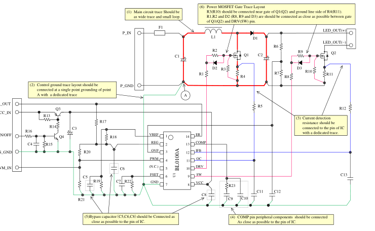
Figure 9-2 Peripheral circuit example around the IC
Page 16
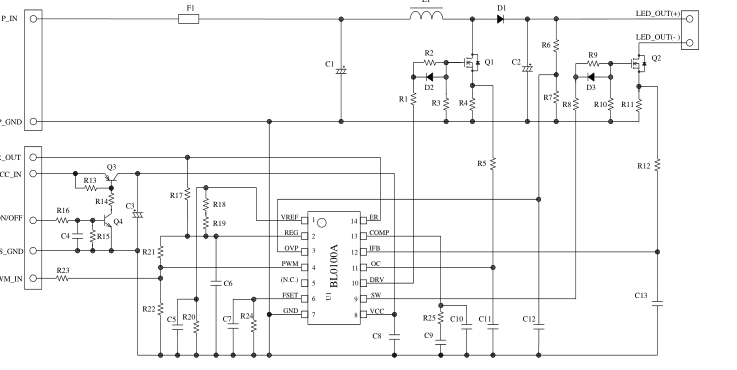
10. Reference Design of Power Supply
As an example, the following show a power supply specification, circuit schematic, bill of materials, and transformer specification.
This reference design is the example of the value of parts, and should be adjusted based on actual operation in the application.
Power Supply Specification
| IC | BL0100A |
| Input voltage | DC 24 V |
| Maximum output power | 20 W (max.) |
| DRV pin oscillation frequency | 100 kHz |
| Output voltage | 50 V |
| Output current | 400 mA |
Circuit Schematic
L1
Page 17
Bill of Materials
| Symbol | Part type | Ratings(1) | Recommended Sanken Parts | Symbol | Part type | Ratings(1) | Recommended Sanken Parts |
|---|---|---|---|---|---|---|---|
| F1 | Fuse | 3 A | R3 | General, chip, 2012 | 10 kΩ | ||
| L1 | Inductor | 50 μH, 3 A | R4 | General | 0.22 Ω, 2 W | ||
| D1 | Fast recovery | 200 V, 1.5 A | EL 1Z | R5 | General, chip, 2012 | 100 Ω | |
| D2 | Schottky | 30 V, 1 A | SJPA-D3 | R6 (3) | General, chip, 2012 | 220 kΩ | |
| D3 | Schottky | 30 V, 1 A | SJPA-D3 | R7 (2) | General, chip, 2012 | 11 kΩ | |
| Q1 | Power MOSFET | 200 V, 45 mΩ (typ.) | SKP202 | R8 | General, chip, 2012 | 470 Ω | |
| Q2 | Power MOSFET | 100 V, 1 Ω (typ.) | R9 | General, chip, 2012 | 1.5 kΩ | ||
| Q3 | PNP Transistor | −50 V, 0.1 A | R10 | General, chip, 2012 | 10 kΩ | ||
| Q4 | NPN Transistor | 50 V, 0.1 A | R11 | General, chip, 2012 | 1.35 Ω, 11 W | ||
| C1 | Electrolytic | 50 V, 22 μF | R12 | General, chip, 2012 | 1.5 kΩ | ||
| C2 | Electrolytic | 100 V, 100 μF | R13 | General, chip, 2012 | 10 kΩ | ||
| C3 | Electrolytic | 50 V, 47 μF | R14 | General, chip, 2012 | 12 kΩ | ||
| C4 | Ceramic, chip, 2012 | 50 V, 0.1 μF | R15 | General, chip, 2012 | 10 kΩ | ||
| C5 | Ceramic, chip, 2012 | 0.1 μF | R16 | General, chip, 2012 | 15 kΩ | ||
| C6 | Ceramic, chip, 2012 | 0.1 μF | R17 | General, chip, 2012 | 10 kΩ | ||
| C7 | Ceramic, chip, 2012 | 0.1 μF | R18 | General, chip, 2012 | 82 kΩ | ||
| C8 (2) | Ceramic, chip, 2012 | 50 V, 0.1 μF | R19 (2) | General, chip, 2012 | 560 Ω | ||
| C9 | Ceramic, chip, 2012 | 0.047 μF | R20 | General, chip, 2012 | 10 kΩ | ||
| C10 | Ceramic, chip, 2012 | 2200 pF | R21 | General, chip, 2012 | 10 kΩ | ||
| C11 | Ceramic, chip, 2012 | 100 pF | R22 | General, chip, 2012 | 33 kΩ | ||
| C12 (2) | Ceramic, chip, 2012 | 10 nF | R23 | General, chip, 2012 | 1 kΩ | ||
| C13 (2) | Ceramic, chip, 2012 | 100 pF | R24 | General, chip, 2012 | Open | ||
| R1 | General, chip, 2012 | 10 Ω | R25 | General, chip, 2012 | 22 kΩ | ||
| R2 | General, chip, 2012 | 100 Ω | U1 | IC | BL0100A |
(1) Unless otherwise specified, the voltage rating of capacitor is 50V or less, and the power rating of resistor is 1/8W or less. (2) It is necessary to be adjusted based on actual operation in the application. (3) Resistors applied high DC voltage and of high resistance are recommended to select resistors designed against electromigration or use combinations of resistors in series for that to reduce each applied voltage, according to the requirement of the application.
Page 18
OPERATING PRECAUTIONS
In the case that you use Sanken products or design your products by using Sanken products, the reliability largely depends on the degree of derating to be made to the rated values. Derating may be interpreted as a case that an operation range is set by derating the load from each rated value or surge voltage or noise is considered for derating in order to assure or improve the reliability. In general, derating factors include electric stresses such as electric voltage, electric current, electric power etc., environmental stresses such as ambient temperature, humidity etc. and thermal stress caused due to self-heating of semiconductor products. For these stresses, instantaneous values, maximum values and minimum
values must be taken into consideration. In addition, it should be noted that since power devices or IC’s including power devices have large self-heating value, the degree of derating of junction temperature affects the reliability significantly.
Because reliability can be affected adversely by improper storage environments and handling methods, please observe the following cautions. Cautions for Storage Ensure that storage conditions comply with the standard temperature (5 to 35°C) and the standard relative humidity (around 40 to 75%); avoid storage locations that experience extreme changes in temperature or humidity. Avoid locations where dust or harmful gases are present and avoid direct sunlight. Reinspect for rust on leads and solderability of the products that have been stored for a long time. Cautions for Testing and Handling When tests are carried out during inspection testing and other standard test periods, protect the products from power
surges from the testing device, shorts between the product pins, and wrong connections. Ensure all test parameters are within the ratings specified by Sanken for the products. Soldering When soldering the products, please be sure to minimize the working time, within the following limits:
- 260 ± 5 °C
10 ± 1 s (Flow, 2 times)
- 380 ± 10 °C 3.5 ± 0.5 s (Soldering iron, 1 time)
Electrostatic Discharge When handling the products, the operator must be grounded. Grounded wrist straps worn should have at least 1MΩ of resistance from the operator to ground to prevent shock hazard, and it should be placed near the operator. Workbenches where the products are handled should be grounded and be provided with conductive table and floor mats. When using measuring equipment such as a curve tracer, the equipment should be grounded. When soldering the products, the head of soldering irons or the solder bath must be grounded in order to prevent leak voltages generated by them from being applied to the products. The products should always be stored and transported in Sanken shipping containers or conductive containers, or
be wrapped in aluminum foil.
Page 19
IMPORTANT NOTES
The contents in this document are subject to changes, for improvement and other purposes, without notice. Make sure that this is the latest revision of the document before use. Application and operation examples described in this document are quoted for the sole purpose of reference for the use of the products herein and Sanken can assume no responsibility for any infringement of industrial property rights, intellectual property rights or any other rights of Sanken or any third party which may result from its use. Unless otherwise agreed in writing by Sanken, Sanken makes no warranties of any kind, whether express or implied, as to the products, including product merchantability, and fitness for a
particular purpose and special environment, and the information, including its accuracy, usefulness, and reliability, included in this document. Although Sanken undertakes to enhance the quality and reliability of its products, the occurrence of failure and defect of semiconductor products at a certain rate is inevitable. Users of Sanken products are requested to take, at their own risk, preventative measures including safety design of the equipment or systems against any possible injury, death, fires or damages to the society due to device failure or malfunction. Sanken products listed in this document are designed and intended for the use as components in general
purpose electronic equipment or apparatus (home appliances, office equipment, telecommunication equipment, measuring equipment, etc.). When considering the use of Sanken products in the applications where higher reliability is required (transportation equipment and its control systems, traffic signal control systems or equipment, fire/crime alarm systems, various safety devices, etc.), and whenever long life expectancy is required even in general purpose electronic equipment or apparatus, please contact your nearest Sanken sales representative to discuss, prior to the use of the products herein. The use of Sanken products without the written consent of Sanken in the applications where extremely high
reliability is required (aerospace equipment, nuclear power control systems, life support systems, etc.) is strictly prohibited. When using the products specified herein by either (i) combining other products or materials therewith or (ii) physically, chemically or otherwise processing or treating the products, please duly consider all possible risks that may result from all such uses in advance and proceed therewith at your own responsibility. Anti radioactive ray design is not considered for the products listed herein. Sanken assumes no responsibility for any troubles, such as dropping products caused during transportation out of Sanken’s distribution network.
The contents in this document must not be transcribed or copied without Sanken’s written consent.