

 Download PDF
BF4M HIROSE
Document overview
- PDF pages: 8
Technical content
Page 1

Overview
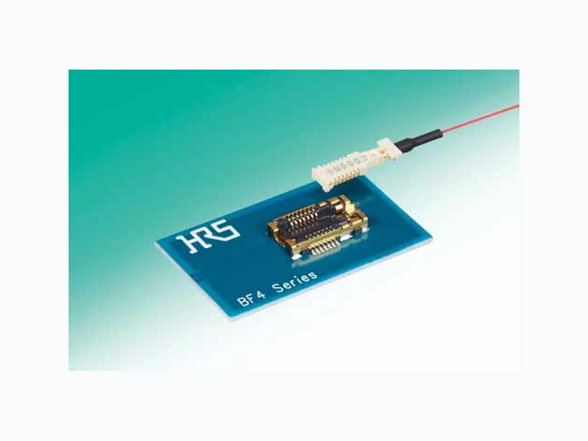
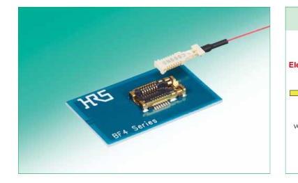
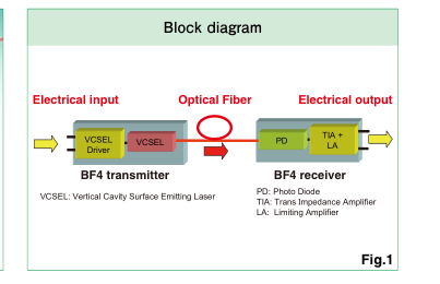
Hirose developed the micro "BF4MC connector" that enables optical transmission of data between boards that are incorporated in devices. It converts an electrical signal that is received from a board by using the semiconductor component built-in the connector, and transfers the data via optical fiber. BF4MC connector is a revolutionary design that enables easy use of electromagnetic noise-free, insulated, longdistance, high-speed transmission. These are the merits of the optical transmission, mounted inside devices achieving dramatic downsizing and lower power consumption when compared to existing optical products. It can be used in a wide range of applications, medic
alappliances Measurement equipments, FA system etc.
Features
1. Optical transmissions achieved by
simplified electrical connections
Optical signal transmission is accomplished with electronic connectors and has eliminated the need for cleaning the mating faces of traditional fiber optic connectors.
2. High-speed, signal transmissions with
no EMI noise.
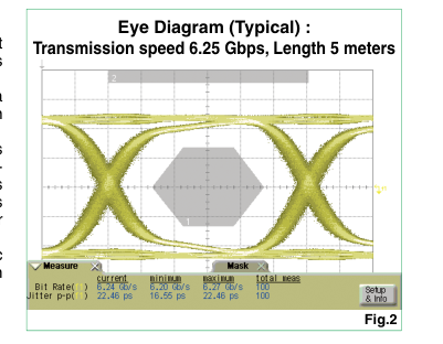
Optical signal transmissions rated up to 6.25 Gbps are possible. Since there is no EMI noise to contend with on the signal lines, system design time is reduced.
3. Highly flexible optical fiber
Assemblies are made with a highly flexible, optical fiber that allows for tight bend radiuses when used in small devices.
4. Long-distance, high-speed and high
quality signal transmissions
The BM4M design is capable of high speed and high quality signal transmissions even over long transmission distances.
5. Low power consumption
Power consumption is significantly reduced compared to conventional optical transceiver.
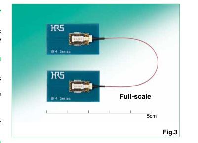
6. Space-saving and low profile
design with 1.5mm height
By using the BF4M, optical transmissions can be achieved with small form factor electronic connectors that save on overall size and valuable PCB space.
In cases where the application will demand a high level of reliability, such as automotive,
2016.2e
please contact a company representative for further information.
Page 2
Electrical characteristics
Electrical characteristics of BF4MC-TX (transmitter side)
| Min | Nominal | Max | Unit | |
|---|---|---|---|---|
| Transmission speed (8B/10B) | 0.05 | ---------- | 6.25 | Gbps |
| VDD voltage | 2.25 | 2.5/3.3 | 3.6 | V |
| ACTIVATE = H voltage | 1.0 | ---------- | VDD voltage | V |
| DIN common voltage | 150 | ---------- | 340 | mVp |
| DIN differential voltage | 200 | ---------- | 1400 | mVp |
Electrical characteristics of BF4MC-RX (receiver side)
| Min | Nominal | Max | Unit | Remarks | |
|---|---|---|---|---|---|
| Transmission speed (8B/10B) | 0.05 | ---------- | 6.25 | Gbps | ---------- |
| VDD voltage | 2.25 | 2.5/3.3 | 3.6 | V | ---------- |
| VDD 15 voltage | 1.45 | 1.5 | 1.55 | V | When driving with dual power sources |
| DOUT common voltage | 160 | ---------- | 330 | mVp | ---------- |
| DOUT differential voltage | 160 | ---------- | 330 | mVp | ---------- |
| SD = H voltage | 1.0 | 1.5 | 1.6 | V | ---------- |
| Imon | 20.0 | ---------- | ---------- | uA | For internal inspection |
<Pin Assignment>
BF4MC-TX Plug
BF4MC-RX Plug
Fiber
Fiber
GND 1
20 GND
GND 1
20 GND
GND 2
GND 2
19 GND
19 GND
GND 3
GND 3 18 GND
18 GND 17 EN
17 ACTIVE Imon 4
VDD 4
16 NC
SD 5 16 NC
GND 5
15 VDD15
VDD 6 15 NC
FILT 6
14 GND
GND 7
14 GND
GND 7 13 DIN-
DIN+ 8
DOUT- 8
13 DOUT+
12 GND GND 9
GND 9
12 GND
11 GND
11 GND GND 10
GND 10
Top View
<Pin Functions>
Descriptions of BF4MC-TX pins
| Synbol | Name | Type | Details |
|---|---|---|---|
| VDD | Vsupply | Power | Power Supply DC+2.5 or +3.3V |
| GND | Ground | Ground | ------- |
| ACTIVE | Activate | Input | H voltage:Active mode L voltage:Sleep mode |
| FILT | Filter | ------- | Decouping condenser connection contact |
| DIN+ | Data input + | Input | Differential Data Input |
| DIN– | Data input – | Input | |
| NC | Not Connect | ------- | Not connected in normal operation |
Descriptions of BF4MC-RX pins
| Synbol | Name | Type | Details |
|---|---|---|---|
| VDD | Vsupply | Power | Power for PD(*) |
| VDD15 | Vdd1.5V | Power | Power for Core(*) |
| GND | Ground | Ground | ------- |
| SD | Signal Detect | Output | H voltage:Detected L voltage:Undetected |
| DOUT+ | Data Output + | Output | Differential Data Output |
| DOUT– | Data Output – | Output | |
| EN | Regulator Enable | Input | [Dual supply mode] Not connected [Single supply mode] EN pin must be connect to VDD |
| Imon | Mirrored photodiode current monitor | Output | Not connected(Inspection pin) |
| NC | Not Connect | ------- | Not connected in normal operation |
(\*): For details, see Hirose's technical specifi cation ETAD-K0671.
Page 3
Product Materials
Plug harnesses
| Port | Details | |
| Transmitter plug(TX) | Housing | LCP(BF4MC:White) |
| Contact | Phosphor bronze (Au plating) | |
| Plate | Phosphor bronze (Ni plating) | |
| VCSEL | GaAs | |
| VCSEL driver | Si(CMOS) | |
| Bonding wire | Au | |
| Sealing resin | Epoxy resin | |
| Heat shrink tubing | Polyolefi n(Black) | |
| Receiver plug(RX) | Housing | LCP(BF4MC:White) |
| Contact | Phosphor bronze (Au plating) | |
| Plate | Phosphor bronze (Ni plating) | |
| PD | GaAs | |
| TIA/LA | Si(CMOS) | |
| Bonding wire | Au | |
| Sealing resin | Epoxy resin | |
| Heat shrink tubing | Polyolefi n(Black) | |
| Optical fi ber | Fiber | Silica glass (GI50/80) |
| Coating | UV curable resin/Thermo plastic resin(Ø0.5) | |
Receptacles
| Port | Details | |
| Transmitter Receptacle(TX) and Receiver Receptacle(RX) | Housing | LCP(Black) |
| Contact | Phosphor bronze (Au plating) | |
| Shell | Phosphor bronze (Au plating) | |
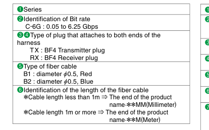
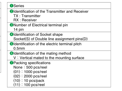
Composition of Product Number
Refer to the product number to determine the product specifi cations.
Plug harness
Receptacle
BF4 - TX - 14 DS - 0.5 V (01)
BF4M C-6G TX RX - B1 - 75MM
❶ ❷ ❸ ❹
❺ ❻
❶ ❷ ❸ ❹
❺ ❻ ❼
Page 4
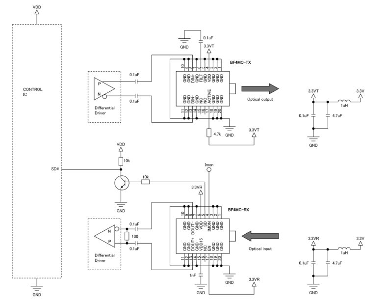
Connection example of +3.3 V (single power supply mode)
Page 5
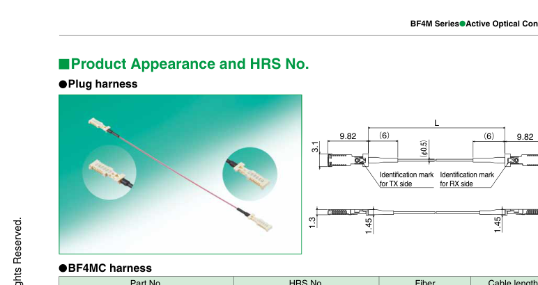
| Part No. | HRS No. | Fiber | Cable length L |
|---|---|---|---|
| BF4MC-6GTXRX-B1-45MM | 831-1102-0 04 | Ø0.5 Red | 45 mm |
| BF4MC-6GTXRX-B1-50MM | 831-1102-0 05 | 50 mm | |
| BF4MC-6GTXRX-B1-55MM | 831-1102-0 06 | 55 mm | |
| BF4MC-6GTXRX-B1-60MM | 831-1102-0 07 | 60 mm | |
| BF4MC-6GTXRX-B1-65MM | 831-1102-0 08 | 65 mm | |
| BF4MC-6GTXRX-B1-70MM | 831-1102-0 09 | 70 mm | |
| BF4MC-6GTXRX-B1-75MM | 831-1102-0 00 | 75 mm | |
| BF4MC-6GTXRX-B1-80MM | 831-1102-0 11 | 80 mm | |
| BF4MC-6GTXRX-B1-85MM | 831-1102-0 12 | 85 mm | |
| BF4MC-6GTXRX-B1-90MM | 831-1102-0 13 | 90 mm | |
| BF4MC-6GTXRX-B1-95MM | 831-1102-0 14 | 95 mm | |
| BF4MC-6GTXRX-B1-100MM | 831-1102-0 15 | 100 mm | |
| BF4MC-6GTXRX-B1-1M | 831-1109-9 00 | 1 m | |
| BF4MC-6GTXRX-B1-2M | 831-1109-9 01 | 2 m | |
| BF4MC-6GTXRX-B1-3M | 831-1109-9 02 | 3 m | |
| BF4MC-6GTXRX-B1-4M | 831-1109-9 03 | 4 m | |
| BF4MC-6GTXRX-B1-5M | 831-1109-9 04 | 5 m |
Length (L) of the harness
- The shortest harness length is 45mm, and the harness up to 100mm in length is available in 5mm increments. (45mm, 50mm, 55mm …, 100mm)
- Harness longer than those listed above is also available upon request. Please inform us of your desired harness length.
- Blue Fiber color is also available. Contact your sales representative for details.
Page 6
Receptacle: Transmitter (TX)
10.25
| 95 | 9.5 3 P=0.5±0.05 (2.05) Vacuum pick up area | |
| 4. 2 (0.25) (1.75) .48±0.1 | ||
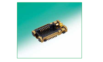
3mm
Vacuum 2.1mm pick up area
- The structure is designed so that the receiver (RX) plug does not mate.
| Part No. | HRS No. Package s |
|---|---|
| BF4-TX-14DS-0.5V | 831-0008-6 00 500 |
| BF4-TX-14DS-0.5V(01) | 831-0008-6 01 1000 |
| BF4-TX-14DS-0.5V(02) | 831-0008-6 02 2000 |
| BF4-TX-14DS-0.5V(10) | 831-0008-6 10 10 p |
| BF4-TX-14DS-0.5V(11) | 831-0008-6 11 100 |
Package specifi cations 500 pcs/reel 1000 pcs/reel 2000 pcs/reel 10 pcs/pack 100 pcs/reel
Receptacle: Receiver (RX)
10.25
| 95 | 9.5 3 P=0.5±0.05 (1.75) Vacuum pick up area | |
| 4. 2. (0.25) (2.05) 1.48±0.1 | ||
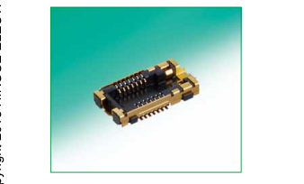
3mm
Vacuum 2.1mm pick up area
- The structure is designed so that the transmitter (TX) plug does not mate.
| Part No. | HRS No. Package s |
|---|---|
| BF4-RX-14DS-0.5V | 831-0009-9 00 500 |
| BF4-RX-14DS-0.5V(01) | 831-0009-9 01 1000 |
| BF4-RX-14DS-0.5V(02) | 831-0009-9 02 2000 |
| BF4-RX-14DS-0.5V(10) | 831-0009-9 10 10 p |
| BF4-RX-14DS-0.5V(11) | 831-0009-9 11 100 |
Package specifi cations 500 pcs/reel 1000 pcs/reel 2000 pcs/reel 10 pcs/pack 100 pcs/reel
Receptacle:Pattern Layout
Recommended PCB land pattern dimensions
Recommended stencil dimensions
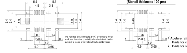
( ) Pads for contacts: 70% Pads for shell: 100%
Page 7
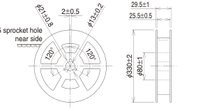
Packaging Specifications for the receptacles
Reel dimensions
Emboss carrier tape dimensions
t=0.3±0.05
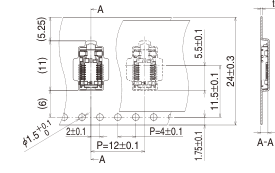
1.6±0.1
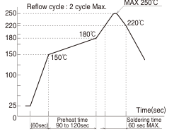
Recommended refl ow temperature profi le (lead-free solder)
Recommended reflow temperature profile (lead-free solder)
MAX 250℃
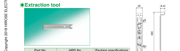
| Part No. | HRS No. | Packing specifications |
|---|---|---|
| BF4-T2 | 831-0006-0 00 | 1 piece |
(2.6)
Page 8
Cautions
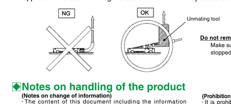
Do not pull the fiber when removing the connector.
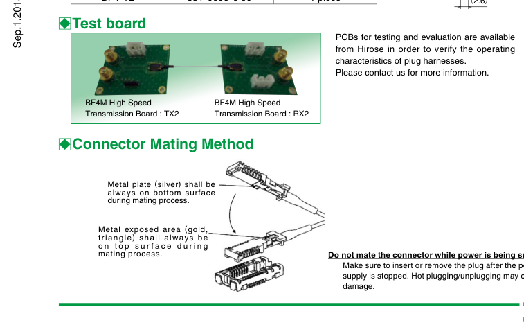
When removing the connector, make sure to hook the plug with an extraction tool so that the stress is not
applied to the cable. Pulling the cable to remove it may cause a breakage in the cable
regarding the connector (hereafter, the Product) is subject to change without prior notice. (Prohibition of reproduction)
- No part of this document may be copied or reproduced without prior written consent of Hirose Electric Co., Ltd. (hereafter, Hirose). Even if written consent of Hirose is obtained, it is prohibited to amend any part of this document and copy or reproduce it. Hirose shall assume no obligation or liability in connection with such amended information or reproduction.
(Responsibilities for design safety)
- Hirose shall assume no responsibilities for the support for the application of the Product or the product design of the customer. The customer shall be responsible for the product and application of the customer in which the Product is used. The customer shall take appropriate design and operational safety measures in order to minimize the potential risks predicted for the product and application of the customer in which the Product is used.
(Responsibilities for determination of the suitability)
- When using the Product, the customer shall ensure safe design at his/her own responsibility so that malfunction or failure of the Product would never cause an infringement on the life, body or property. For design or use of the Product, make sure to refer to the materials (including the catalog, specifications, and design note) and follow the same. When using information including the product data provided in the document, technical data or circuit examples shown in the figures and tables, the customer shall evaluate the information on the customer’s product and determine the suitability at the customer’s own responsibility.
(Responsibilities for specific applications)
- Make sure to consult with our sales representative in advance when considering of use for specific applications that require extremely high quality and reliability (e.g. nuclear equipment, aerospace systems, transportation equipment and various safety related equipment).
(Prohibition of replication)
- Do not disassemble reverse-engineer, modify, analyze or replicate the Product.
(Prohibition of application to prohibited products)
- The Product must not be used for any product that manufacture, use and sale of which is prohibited by the domestic or international laws, regulations and ordinances.
(Notes on the guarantee and license)
- The technical data provided in the materials of the Product is intended to describe the representative behaviors and application of the Product. It is not to guarantee the intellectual property rights or any other rights of Hirose nor a third party and not to grant the license.
(Notes on the warranties for the contract)
- Unless otherwise provided in a written contract or other documents (specifications) agreed between the customer and Hirose, Hirose makes no warranties of any kind (including, but not limited to, warranties of the function and operation, warranties of merchantability, warranties of suitability for a specific application or purpose and warranties of correctness of the information).

(Prohibition of weapons of mass destruction and military purposes)
- It is prohibited to use the Product or the technical information contained in this document for any military purposes, including but not limited to, development of weapons of mass destruction.
(Notes on export)
- To export the Product to other countries, the exporter shall conduct the applicability determination based on Foreign Exchange and Foreign Trade Act of Japan. If you wish to have the applicability determination sheet issued by Hirose, contact our sales representative. Note that in the export arrangement, the customer shall be an exporter and responsible for compliance with all the applicable laws and regulations and terms and conditions of the agreement with Hirose.
Notes on use of the product
(Notes on the specification range)
- Using the Product under conditions beyond the specification range (for voltage, current and temperature) provided in this document may result in an accident (including ignition, heat generation, and smoking). Confirm the document thoroughly and make sure to use the Product within the specification range.
(Notes on the laser)
- The laser beam is emitted from the end-face of the optical fiber in operation. It may cause eye injury or loss of sight if it enters the eyes. Do not stare directly into the end-face of the optical fiber. The laser beam is emitted from the VCSEL in operation. It may not be visible depending on its wavelength, but nonetheless it may cause eye injury or loss of sight if the laser beam or its reflected beam enters the eyes. Do not stare (look into) the laser beam directly.
(Notes on fracture of the optical fiber)
- In case of fracture of the optical fiber used in the Product, turn off the power immediately. In addition, Use care when handling it to avoid injury from fractured parts or fragments.
(Notes on use of GaAs)
- The Product is equipped with a semiconductor within the connector and contains gallium arsenide (GaAs).
(Notes on the environment including gases)
- Avoid the use of the Product in gas environments with chlorides or sulfides. The Product may deteriorate and features may be affected.
(Notes on storage)
- Store the Product out of corrosive substances, corrosive gases, high temperature and humidity or direct sunlight. Do not apply excessive pressure or vibration to the Product. It may cause deterioration, deformation, damage or failure of the Product.
(Notes on resin molded part)
- The resin molded part of the Product may contain black spots or its color may be slightly different, but that has no effect on the product performance.
2-6-3,Nakagawa Chuoh,Tsuzuki-Ku,Yokohama-Shi 224-8540,JAPAN TEL: +81-45-620-3526 Fax: +81-45-591-3726 http://www.hirose.com http://www.hirose-connectors.com
The characteristics and the specifications contained herein are for reference purpose. Please refer to the latest customer drawings prior to use. The contents of this catalog are current as of date of 02/2016. Contents are subject to change without notice for the purpose of improvements.