
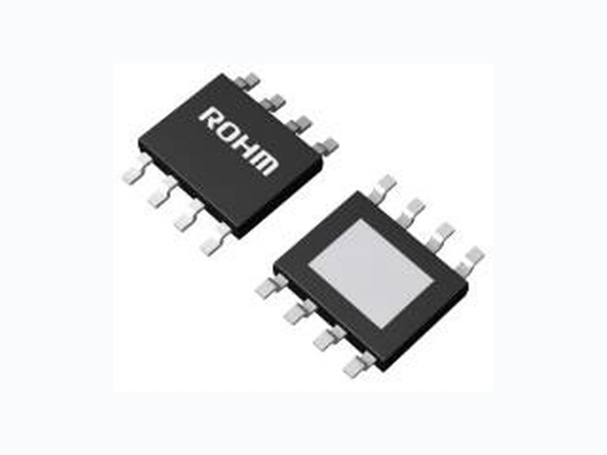
BDL00A5NUF-C ROHM
Document overview
- Manufacturer or author: ROHM CO., LTD.
- PDF pages: 36
Technical content
Features
◼ AEC-Q100 Qualified (Note 2) ◼ Functional Safety Supportive Automotive Products ◼ Output Shutdown Function (EN Function) ◼ Over Current Protection (OCP) ◼ Thermal Shutdown Protection (TSD) (Note 2) Grade 1 Key Specifications ◼ Wide Temperature Range (Tj): -40 °C to +150 °C ◼ Operating Input Range: 2.9 V to 18 V ◼ Current Consumption: 30 µA (Typ) ◼ Shutdown Circuit Current 0 µA (Typ) ◼ Output Current Capability: 500 mA ◼ High ADJ Voltage Accuracy: ±2 % ◼ Output Voltage: 1 V to 17 V (Note 3) It does not contain the current of external feedback resistance.
Applications
◼ Automotive (Power Train, Body ECU) ◼ Car Infotainment System, etc. Package W (Typ) x D (Typ) x H (Max) VSON10FV3030 3.0 mm × 3.0 mm × 1.0 mm HTSOP-J8 4.9 mm × 6.0 mm × 1.0 mm VSON10FV3030 HTSOP-J8 Typical Application Circuit ◼ Components Externally Connected Capacitor: 1.0 µF ≤ CIN, 1.0 µF ≤ COUT (Note 4) Resistor: 10 kΩ ≤ R2 ≤ 200 kΩ (Note 5) VADJ (Typ): 0.75 V (Note 4) Electrolytic capacitor, tantalum capacitor and ceramic capacitors can be used. Set capacitor value which do not fall below CIN =1.0 µF, COUT = 1.0 µF. These values need to consider the temperature characteristics and DC bias characteristics. (Note 5) The tolerance of feedback resistor is not included in the accuracy of output voltage. The value of a feedback resistor R2 must be within this range. R1 value is defined by following the formula using the limitation of R1. 𝑅1 = 𝑅2 (𝑉𝑂𝑈𝑇 𝑉𝐴𝐷𝐽 − 1) VSON10FV3030 HTSOP-J8 VIN VIN GND EN VOUT VOUT ADJ VIN CIN VEN COUT VIN GND EN VOUT ADJ VIN CIN VEN COUT Datasheet
2/33 © 2020 ROHM Co., Ltd. All rights reserved. www.rohm.com BDL00A5NUF-C BDL00A5EFJ -C TSZ22111 • 15 • 001 TSZ02201-0BGB0A300120-1-2 05.Dec.2022 Rev.001
Contents
3/33 © 2020 ROHM Co., Ltd. All rights reserved. www.rohm.com BDL00A5NUF-C BDL00A5EFJ -C TSZ22111 • 15 • 001 TSZ02201-0BGB0A300120-1-2 05.Dec.2022 Rev.001 Pin Configurations Pin Descriptions BDL00A5NUF-C Pin No. Pin Name Function Descriptions 1, 2 VOUT Output Voltage Pin It is necessary to use a capacitor with a capacitance of 1.0 µF (Min) or higher between the VOUT pin and the GND pin. The detail of a selection is described in Selection of External Components.
3 ADJ Adjustment Pin
Connect an external resistor between the VOUT pin and the ADJ pin and between the ADJ pin and the GND pin to adjust output voltage. 4 GND Ground This is ground pin. 5 N.C. - This pin is not connected to the chip. (Note 1)
6 EN Control Output
A logical “HIGH” (VEN ≥ 2.0 V) at the EN pin enables the device and “LOW” (VEN ≤ 0.4 V) at the EN pin disables the device. 7 N.C. - This pin is not connected to the chip. (Note 1) 8 N.C. - This pin is not connected to the chip. (Note 1) 9, 10 VIN Input Supply Voltage Pin It is necessary to use a capacitor with a capacitance of 1.0 µF (Min) or higher between the VIN pin and the GND pin. The detail of a selection is described in Selection of External Components. If the inductance of power supply line is high, adjust input capacitor value. EXP-PAD EXP-PAD Heat Dissipation It is recommended to connect EXP -PAD on the back side to external ground pattern in order to make heat dissipation better. BDL00A5EFJ-C Pin No. Pin Name Function Descriptions
1 VOUT Output Voltage Pin
It is necessary to use a capacitor with a capacitance of 1.0 µF (Min) or higher between the VOUT pin and the GND pin. The detail of a selection is described in Selection of External Components.
2 ADJ Adjustment Pin
Connect an external resistor between the VOUT pin and the ADJ pin and between the ADJ pin and the GND pin to adjust output voltage. 3 GND Ground This is ground pin. 4 N.C. - This pin is not connected to the chip. (Note 1)
5 EN Control Output
A logical “HIGH” (VEN ≥ 2.0 V) at the EN pin enables the device and “LOW” (VEN ≤ 0.4 V) at the EN pin disables the device. 6 N.C. - This pin is not connected to the chip. (Note 1) 7 N.C. - This pin is not connected to the chip. (Note 1)
8 VIN Input Supply Voltage
It is necessary to use a capacitor with a capacitance of 1.0 µF (Min) or higher between the VIN pin and the GND pin. The detail of a selection is described in Selection of External Components. If the inductance of power supply line is high, adjust input capacitor value. EXP-PAD EXP-PAD Heat Dissipation It is recommended to connect EXP -PAD on the back side to external ground pattern in order to make heat dissipation better. (Note 1) The N.C. pin can be either left floated or for connect to GND. VSON10FV3030 (TOP VIEW) HTSOP-J8 (TOP VIEW) BDL00A5NUF-C BDL00A5EFJ-C 1 2 3 4 8 7 6 5 EXP-PAD 5 6
4/33 © 2020 ROHM Co., Ltd. All rights reserved. www.rohm.com BDL00A5NUF-C BDL00A5EFJ -C TSZ22111 • 15 • 001 TSZ02201-0BGB0A300120-1-2 05.Dec.2022 Rev.001 Block Diagrams VSON10FV3030 HTSOP-J8 VREF VOUT (PIN 1) EN (PIN 5) ADJ (PIN 2) VIN (PIN 8) PREREG TSD GND (PIN 3) AMP N.C. (PIN 4) N.C. (PIN 7) N.C. (PIN 6) EN EN EN DIS- CHARGE EN_SIG EN_SIG OCP DRIVER
5/33 © 2020 ROHM Co., Ltd. All rights reserved. www.rohm.com BDL00A5NUF-C BDL00A5EFJ -C TSZ22111 • 15 • 001 TSZ02201-0BGB0A300120-1-2 05.Dec.2022 Rev.001 Description of Blocks Block Name Function Description of Blocks EN Control Output ON / OFF A logical “HIGH” (VEN ≥ 2.0 V) at the EN Pin enables the device and “LOW” (VEN ≤ 0.4 V) at the EN Pin disables the device. PREREG Internal Power Supply Power supply for internal circuit. TSD Thermal Shutdown Protection In case maximum power dissipation is exc eeded or the ambient temperature is higher than the Maximum Junction Temperature, overheating causes the chip temperature (Tj) to rise. The TSD protection circuit detects this and forces the output to turn off in order to protect the device from overheating. (Typ: 175 °C) When the junction temperature decreases to low, the output turns on automatically. VREF Internal Reference Voltage Generate the reference voltage. AMP Error Amplifier Compares the ADJ voltage with the reference voltage and controls the output power transistor via the DRIVER. DRIVER Output MOSFET Driver Drive the output MOSFET OCP Over Current Protection If the output current increases higher than the maximum output current, it is limited by Over Current Protection in order to protect the device from a damage caused by an over current. (Typ: 800 mA) While this block is operating, the output voltage may decrease because the output current is limited. If an abnormal state is removed and the output current value returns to normal, the output voltage also returns to normal state. DISCHARGE Output Discharge Function Output pin is discharged by the internal resistance when EN = LOW input or TSD is detected. Absolute Maximum Ratings Parameter Symbol Ratings Unit Input Voltage (Note 1) VIN -0.3 to +20 V EN Pin Voltage (Note 2) VEN -0.3 to +20 V VOUT Pin Voltage VOUT -0.3 to +20 (≤ VIN + 0.3) V ADJ Pin Voltage VADJ -0.3 to +7 V Junction Temperature Range Tj -40 to +150 °C Storage Temperature Range Tstg -55 to +150 °C Maximum Junction Temperature Tjmax 150 °C ESD Withstand Voltage (HBM) (Note 3) VESD_HBM ±2000 V ESD Withstand Voltage (CDM) (Note 4) VESD_CDM ±750 V Caution 1: Operating the IC over the absolute maximum ratings may damage the IC. The damage can either be a short circuit between pins o r an open circuit between pins and the internal circuitry. Therefore, it is important to consider circuit protection measures, such as adding a fuse, in case the IC is operated over the absolute maximum ratings. Caution 2: Should by any chance the maximum junction temperature rating be exceeded the rise in temperature of the chip may result in deterioration of the properties of the chip. In case of exceeding this absolute maximum rating, design a PCB with thermal resistance and power dissipation taken into consideration by increasing board size and copper area so as not to exceed the maximum junction temperature rating. (Note 1) Do not exceed Tjmax. (Note 2) The start-up orders of input voltage (VIN) and the VEN do not influence if the voltage is within the operation power supply voltage range. (Note 3) ESD susceptibility Human Body Model “HBM”; base on ANSI/ESDA/JEDEC JS001 (1.5 kΩ, 100 pF). (Note 4) ESD susceptibility Charged Device Model “CDM”; base on AEC-Q100-011.
6/33 © 2020 ROHM Co., Ltd. All rights reserved. www.rohm.com BDL00A5NUF-C BDL00A5EFJ -C TSZ22111 • 15 • 001 TSZ02201-0BGB0A300120-1-2 05.Dec.2022 Rev.001 Thermal Resistance Parameter Symbol Thermal Resistance (Typ) (Note 1) Unit 1s (Note 3) 2s2p (Note 4) VSON10FV3030 Junction to Ambient θJA 168.2 46.9 °C/W Junction to Top Characterization Parameter (Note 2) ΨJT 20 9 °C/W HTSOP-J8 Junction to Ambient θJA 139.0 35.6 °C/W Junction to Top Characterization Parameter (Note 2) ΨJT 18 7 °C/W (Note 1) Based on JESD51-2A (Still-Air). Using BDL00A5NUF-C, BDL00A5EFJ-C chip. (Note 2) The thermal characterization parameter to report the difference between junction temperature and the temperature at the top center of the outside surface of the component package. (Note 3) Using a PCB board based on JESD51-3. (Note 4) Using a PCB board based on JESD51-5, 7. Layer Number of Measurement Board Material Board Size Single FR-4 114.3 mm x 76.2 mm x 1.57 mmt Top Copper Pattern Thickness Footprints and Traces 70 µm Layer Number of Measurement Board Material Board Size Thermal Via (Note 5) Pitch Diameter Top 2 Internal Layers Bottom Copper Pattern Thickness Copper Pattern Thickness Copper Pattern Thickness Footprints and Traces 70 µm 74.2 mm x 74.2 mm 35 µm 74.2 mm x 74.2 mm 70 µm (Note 5) This thermal via connects with the copper pattern of layers 1,2, and 4. The placement and dimensions obey a land pattern. Operating Conditions (-40 °C ≤ Tj ≤ +150 °C) Parameter Symbol Min Max Unit Input Voltage(Note 1) VIN VOUT (Max) + ΔVd (Max) 18 V Start-up Voltage(Note 2) VIN Start-Up 2.4 - V Output Voltage VOUT 1 17 V EN Pin Voltage VEN 0 18 V Output Current IOUT 0 500 mA Feedback Resistor ADJ vs GND R2 10 200 kΩ Input Capacitor(Note 3) (Note 4) CIN 1 - µF Output Capacitor(Note 4) COUT 1 100 µF Output Capacitor Equivalent Series Resistance ESR(COUT) - 5 Ω Operating Temperature Ta -40 +125 °C (Note 1) Minimum Input Voltage must be 2.9 V or more. Consider that the output voltage would be dropped (Dropout voltage ΔVd) by the output current. (Note 2) In case of VOUT setting 2.4 V or less, VOUT (Min) = 90 % × VOUT (Typ) with VIN = 2.4 V, IOUT = 0 mA. (Note 3) If the inductance of power supply line is high, adjust input capacitor value. (Note 4) Set capacitor value which do not fall below the minimum value. This value needs to consider the temperature characteristics and DC bias characteristics.
7/33 © 2020 ROHM Co., Ltd. All rights reserved. www.rohm.com BDL00A5NUF-C BDL00A5EFJ -C TSZ22111 • 15 • 001 TSZ02201-0BGB0A300120-1-2 05.Dec.2022 Rev.001
Electrical Characteristics
Unless otherwise specified, Tj = -40 °C to +150 °C, VIN = VOUT + 1.0 V (Note 1), VEN = 5 V, IOUT = 0 mA, CIN = 2.2 µF, COUT = 2.2 µF VOUT setting = 5 V, R1 = 255 kΩ (180 kΩ + 75kΩ), R2 = 45 kΩ (30 kΩ + 15 kΩ) Typical values are defined at Tj = 25 °C, VIN = 6 V Parameter Symbol Limits Unit Conditions Min Typ Max Shutdown Current ISHUT - 0 1 µA VEN = 0 V, Tj = 25 °C - 0 5 VEN = 0 V, Tj ≤ 125 °C Current Consumption(Note 2) ICC - 30 45 µA Tj = 25 °C VIN = 6 V, IOUT = 0 mA - 35 65 Tj ≤ 125 °C VIN = 6 V, IOUT = 0 mA Reference Voltage VADJ 0.735 0.750 0.765 V VOUT + 1.0 V ≤ VIN ≤ 18 V (VIN ≥ 2.9 V) 0.1 mA ≤ IOUT ≤ 500 mA Dropout Voltage ΔVd - 0.28 - V VOUT = 5 V VIN = 4.75 V (VOUT × 0.95) IOUT = 500 mA - - 0.60 VOUT = 2.9 V to 17 V VIN = VOUT × 0.95 IOUT = 500 mA Ripple Rejection R.R. - 65 - dB f = 1 kHz, VRipple = 0.1 Vrms IOUT = 100 mA, VIN = 6 V Line Regulation Reg.I - 0.08 0.20 % VOUT + 1.0 V ≤ VIN ≤ 18 V (Note 3) Load Regulation Reg.L - 0.3 0.8 % 0.1 mA ≤ IOUT ≤ 500 mA Output Short Current IOUT(SHORT) - 150 400 mA VOUT + 1.0 V ≤ VIN ≤ 18 V (Note 3) VOUT = 0 V ADJ Input Current(Note 4) IADJ - - 100 nA VADJ = 1 V Thermal Shutdown Temperature Tj (TSD) 151 175 - °C - (Note 1) VOUT ≤ 1.9 V, VIN = 2.9 V (Note 2) It does not contain the current of R1 and R2. (Note 3) VOUT ≤ 1.9 V, 2.9 V ≤ VIN ≤ 18 V (Note 4) Not all devices are measured for shipment Enable Function Unless otherwise specified, Tj = -40 °C to +150 °C, VIN = VOUT + 1.0 V (Note 1), VEN = 5 V, IOUT = 0 mA, CIN = 2.2 µF, COUT = 2.2 µF VOUT setting = 5 V, R1 = 255 kΩ (180 kΩ + 75kΩ), R2 = 45 kΩ (30 kΩ + 15 kΩ) Typical values are defined at Tj = 25 °C, VIN = 6 V Parameter Symbol Limits Unit Conditions Min Typ Max EN ON mode Voltage VENH 2 - 18 V - EN OFF mode Voltage VENL 0 - 0.4 V - EN Bias Current IEN - 1.7 5.0 µA -
19/33 © 2020 ROHM Co., Ltd. All rights reserved. www.rohm.com BDL00A5NUF-C BDL00A5EFJ -C TSZ22111 • 15 • 001 TSZ02201-0BGB0A300120-1-2 05.Dec.2022 Rev.001 Application and Implementation Notice: The following information is given as a reference or hint for the application and the implementation. Therefore, it does not guarantee its operation on the specific function , accuracy or external components in the application. In the application, it shall be designed with sufficient margin by enough understanding about characteristics of the external components, e.g. capacitor, and also by appropriate verification in the actual operating conditions. Selection of External Components Input Pin Capacitor If the battery is placed far from the regulator or the impedance of the input-side is high, higher capacitance is required for the input capacitor in order to prevent the voltage-drop at the input line. The input capacitor and its capacitance should be selected depending on the line impedance which is between the input pin and the smoothing filter circ uit of the power supply. At this time, the capacitance value setting is different each application. Generally, the capacitor with capacitance value of 1.0 µF (Min) with good high frequency characteristic is recommended for this regulator. In addition, the consideration should be taken as the out put pin capacitor, to prevent an influence to the regulator ’s characteristic from the deviation or the variation of the external capacitor ’s characteristic. All output capacitors mentioned above are recommended to h ave a good DC bias characteristic and a temperature characteristic (approximately ±15 %, e.g. X7R, X8R) with being satisfied high absolute maximum voltage rating based on EIA standard. These capacitors should be placed close to the input pin and mounted on the same board side of the regulator not to be influenced by implement impedance. Output Pin Capacitor The output capacitor is mandatory for the regulator i n order to realize stable operation. The output capacitor with capacitance value ≥ 1.0 µF (Min) and ESR up to 5 Ω (Max) must be required between the output pin and the GND pin. A proper selection of appropriate both the capacitance value and ESR for the output capacitor can improve the transient behavior of the regulator and can also keep the stability with better regulation loop. The correlation of the output capacitance value and ESR is shown in the graph on the next page as the output capacitor’s capacitance value and the stability region for ESR. As described in this graph, this regulator is designed to be stable with ceramic capacitors as of MLCC, with the capacitance value from 1.0 µF (Min) to 100 µF (Max) and with ESR value within almost 0 Ω to 5 Ω. The frequency range of ESR can be generally considered as within about 10 kHz to 100 kHz. Note that the provided the stable area of the capacitance value and ESR in the graph is obtained under a specific set of conditions which is based on the measurement result in sin gle IC on our board with a resistive load. I n the actual environment, the stability is affected by wire impedance on the board, input power supply impedance and also loads impedance. Therefore, note that a careful evaluation of the actual application, the actual usage environment and the actual conditions should be done to confirm the actual stability of the system. Generally, in the transient event which is caused by the input voltage fluctuation or the load fluctuation beyond the gain bandwidth of the regulation loop, the transient response ability of the regulator depends on the capacitance value of the output capacitor. Basically the capacitance value of ≥ 1.0 µF (Min) for the output capacitor is recommended as shown in the table on Output Capacitance COUT, ESR Available Area. Using bigger capacitance value can be expected to improve better the transient response ability in a high frequency. Various types of capacitors c an be used for the output capacitor with high capacity which includes electrolytic capacitor, electro-conductive polymer capacitor and tantalum capacitor. Noted that, depending on the type of capacitor s, its characteristics such as ESR (≤ 5 Ω) absolute value range, a temperature dependency of capacitance value and increased ESR at cold temperature needs to be taken into consideration . When using capacitor with large ESR (> 5 Ω), note that ceramic capacitor with 1.0 µF (Min) or higher must be connected in parallel to keep stability. In this case, the total capacitance should be less than 100 µF (Max). In addition, the same consideration should be taken as the input pin capacitor, to prevent an influence to the regulator ’s characteristic from the deviation or the variation of the external capacitor ’s characteristic. All output capacitors mentioned above are recommended to have a good DC bias characteristic and a temperature characteristic (approximately ±15 %, e.g. X7R, X8R) with being satisfied high absolute maximum voltage rating based on EIA standard. These capacitors should be placed close to the output pin and mounted on the same board side of the regulator not to be influenced by implement impedance.
20/33 © 2020 ROHM Co., Ltd. All rights reserved. Figure 40. Output Capacitance COUT, ESR Available Area (Note 1) If the inductance of power supply line is high, adjust input capacitor value . to small as much as possible.
22/33 © 2020 ROHM Co., Ltd. All rights reserved. www.rohm.com BDL00A5NUF-C BDL00A5EFJ -C TSZ22111 • 15 • 001 TSZ02201-0BGB0A300120-1-2 05.Dec.2022 Rev.001 Protection against Reverse Input/Output Voltage – continued An effective solution for this problem is to implement an external bypass diode in order to prevent the reverse current flow inside the IC as shown in Figure 44. Especially in applications where the output voltage setting is high and a large output capacitor is connected, be sure to consider countermeasures for large reverse current values. Note that the bypass diode must be turned on prior to the internal body diode of the IC. This external bypass diode should be chosen as being lower forward voltage VF than the internal body diode. It should to be selected a diode which has a rated reverse voltage greater than the IC’s input maximum voltage and also which has a rated forward current greater than the anticipated reverse current in the actual application. Figure44. Bypass Diode for Reverse Current Diversion A schottky barrier diode which has a characteristic of low forward voltage (V F) can meet to the requirement for the external diode to protect the IC from the reverse current. However, it also has a characteristic that the leakage (I R) caused by the reverse voltage is bigger than other diodes. Therefore , it should be taken into the consideration to choose it because if IR is large, it may cause increase of the current consumption, or raise of the output voltage in the light-load current condition. IR characteristic of schottky diode has positive temperature characteristic, which the details shall be checked with the datasheet of the products, and the careful confirmation of behavior in the actual application is mandatory. Even in the condition when the input/output voltage is inverted, if the VIN pin is open as shown in Figure 45, or if the VIN pin becomes high-impedance condition as designed in the system, it cannot damage or degrade the parasitic element. It's because a reverse current via the pass transistor becomes extremely low. In this case, therefore, the protection external diode is not necessary. Figure45. Open VIN Protection against Input Reverse Voltage When the input of the IC is connected to the power supply, accidentally if plus and minus are routed in reverse, or if there is a possibility that the input may become lower than the GND pin, it may cause to destroy the IC because a large current passes via the internal electrostatic breakdown prevention diode between the VIN pin and the GND pin inside the IC as shown in Figure 46. The simplest solution to avoid this problem is to connect a schottky barrier diode or a rectifier diode in series to the power supply line as shown in Figure 47. However, it increases a power loss calculated as VF x ICC, and it also causes the voltage drop by a forward voltage VF at the supply voltage while normal operation. Generally, since the schottky barrier diode has lower V F, so it contributes to rather smaller power loss than rectifier diodes. If IC has load currents, the required input current to the IC is also bigger . In this case , this external diod e generates heat more, therefore select a diode with enough margin in power dissipation. On the other hand, a reverse current passes this diode in the reverse connection condition, however, it is negligible because its small amount. Figure46. Current Path in Reverse Input Connection Figure47. Protection against Reverse Polarity 1 VIN VOUT GND CIN ON→OFF IBIAS VIN COUT VOUT VOUTVIN VOUT GND VIN CIN COUT VIN VOUT GND VIN CIN GND GND COUT VOUT VIN VOUT GND VIN CIN COUT VOUT
25/33 © 2020 ROHM Co., Ltd. All rights reserved. www.rohm.com BDL00A5NUF-C BDL00A5EFJ -C TSZ22111 • 15 • 001 TSZ02201-0BGB0A300120-1-2 05.Dec.2022 Rev.001 Thermal Design This product exposes a frame on the back side of the package for thermal efficiency improvement. The power consumption of the IC is decided by the dropout voltage condition, the load current and the current consumption. Refer to power dissipation curves illustrated in Figure 51 and Figure 52 when using t he IC in an environment of Ta ≥ 25 °C. Even if the ambient temperature Ta is at 25 °C, chip junction temperature (Tj) can be very high depending on the input voltage and the load current. Consider the design to be Tj ≤ Tjmax = 150 °C in whole operating temperature range. Should by any condition the maximum junction temperature Tjmax = 150 °C rating be exceeded by the temperature increase of the chip, it may result in deterioration of the properties of the chip. The thermal impedance in this specification is based on recommended PCB and measurement condition by JEDEC standard. Therefore, need to be careful because it might be different from the actual use condition. Verify the application and allow sufficient margins in the thermal design by the following method to calculate the junction temperature Tj. Tj can be calculated by either of the two following methods. 1. The following method is used to calculate the junction temperature Tj with ambient temperature Ta. 𝑇𝑗 = 𝑇𝑎 + 𝑃𝐶 × 𝜃𝐽𝐴 [°C] Where: Tj is the Junction Temperature Ta is the Ambient Temperature PC is the Power Consumption θJA is the Thermal Resistance (Junction to Ambient) 2. The following method is also used to calculate the junction temperature Tj with top center of case’s (mold) temperature TT. 𝑇𝑗 = 𝑇𝑇 + 𝑃𝐶 × 𝛹𝐽𝑇 [°C] Where: Tj is the Junction Temperature TT is the Top Center of Case’s (mold) Temperature PC is the Power consumption ΨJT is the Thermal Resistance (Junction to Top Center of Case) 3. The following method is used to calculate the power consumption Pc (W). 𝑃𝑐 = (𝑉𝐼𝑁 − 𝑉𝑂𝑈𝑇) × 𝐼𝑂𝑈𝑇 + 𝑉𝐼𝑁 × 𝐼𝐶𝐶 [W] Where: PC is the Power Consumption VIN is the Input Voltage VOUT is the Output Voltage IOUT is the Load Current ICC is the Current Consumption
26/33 © 2020 ROHM Co., Ltd. All rights reserved. www.rohm.com BDL00A5NUF-C BDL00A5EFJ -C TSZ22111 • 15 • 001 TSZ02201-0BGB0A300120-1-2 05.Dec.2022 Rev.001 Thermal Design – continued Calculation Example (VSON10FV3030) If VIN = 6.0 V, VOUT = 5.0 V, IOUT = 250 mA, ICC = 104 µA (the Current Consumption at IOUT = 250 mA), the power consumption Pc can be calculated as follows: 𝑃𝐶 = (𝑉𝐼𝑁 − 𝑉𝑂𝑈𝑇) × 𝐼𝑂𝑈𝑇 + 𝑉𝐼𝑁 × 𝐼𝐶𝐶 = (6.0 𝑉 – 5.0 𝑉) × 250 𝑚𝐴 + 6.0 𝑉 × 104 𝜇𝐴 = 0.25 𝑊 At the maximum ambient temperature Tamax = 85 °C, the thermal impedance (Junction to Ambient) θJA = 46.9 °C/W (4-layer PCB) 𝑇𝑗 = 𝑇𝑎𝑚𝑎𝑥 + 𝑃𝐶 × 𝜃𝐽𝐴 = 96.7 °𝐶 When operating the IC, the top center of case’s (mold) temperature TT = 100 °C, ΨJT = 20 °C/W (1-layer PCB) 𝑇𝑗 = 𝑇𝑇 + 𝑃𝐶 × 𝛹𝐽𝑇 = 105.0 °𝐶 If it is difficult to ensure the margin by the calculations above, it is recommended to expand the copper foil area of the board, increasing the layer and thermal via between thermal land pad for optimum thermal performance. Calculation Example (HTSOP-J8) If VIN = 6.0 V, VOUT = 5.0 V, IOUT = 250 mA, ICC = 104 µA (the Current Consumption at IOUT = 250 mA), the power consumption Pc can be calculated as follows: 𝑃𝐶 = (𝑉𝐼𝑁 − 𝑉𝑂𝑈𝑇) × 𝐼𝑂𝑈𝑇 + 𝑉𝐼𝑁 × 𝐼𝐶𝐶 = (6.0 𝑉 – 5.0 𝑉) × 250 𝑚𝐴 + 6.0 𝑉 × 104 𝜇𝐴 = 0.25 𝑊 At the maximum ambient temperature Tamax = 85 °C, the thermal impedance (Junction to Ambient) θJA = 35.6 °C/W (4-layer PCB) 𝑇𝑗 = 𝑇𝑎𝑚𝑎𝑥 + 𝑃𝐶 × 𝜃𝐽𝐴 = 93.9 °𝐶 When operating the IC, the top center of case’s (mold) temperature TT = 100 °C, ΨJT = 18 °C/W (1-layer PCB) 𝑇𝑗 = 𝑇𝑇 + 𝑃𝐶 × 𝛹𝐽𝑇 = 104.5 °𝐶 If it is difficult to ensure the margin by the calculations above, it is recommended to expand the copper foil area of the board, increasing the layer and thermal via between thermal land pad for optimum thermal performance.
27/33 © 2020 ROHM Co., Ltd. All rights reserved. www.rohm.com BDL00A5NUF-C BDL00A5EFJ -C TSZ22111 • 15 • 001 TSZ02201-0BGB0A300120-1-2 05.Dec.2022 Rev.001 I/O Equivalence Circuit (Note 1) Resistance value is Typical. VIN Pin EN Pin(Note 1) ADJ Pin(Note 1) VOUT Pin(Note 1) VIN Internal Circuit EN 0.3 MΩ 1.3 MΩ 1.35 MΩ 10 kΩ ADJ 15 kΩ 500 kΩ 5 MΩ VIN VOUT VIN 4 kΩ 1 kΩ 100 Ω 100 Ω 8.4 kΩ VIN
28/33 © 2020 ROHM Co., Ltd. All rights reserved. www.rohm.com BDL00A5NUF-C BDL00A5EFJ -C TSZ22111 • 15 • 001 TSZ02201-0BGB0A300120-1-2 05.Dec.2022 Rev.001 Operational Notes 1. Reverse Connection of Power Supply Connecting the power supply in reverse polarity can damage the IC. Take precautions against reverse polarity when connecting the power supply, such as mounting an external diode between the power supply and the IC’s power supply pins. 2. Power Supply Lines Design the PCB layout pattern to provide low impedance supply lines. Furthermore, connect a capacitor to ground at all power supply pins. Consider the effect of temperature and aging on the capacitance value when using electrolytic capacitors. 3. Ground Voltage Ensure that no pins are at a voltage below that of the ground pin at any time, even during transient condition. 4. Ground Wiring Pattern When using both small-signal and large-current ground traces, the two ground traces should be routed separately but connected to a single ground at the reference point of the application board to avoid fluctuations in the small -signal ground caused by large currents. Also ensure that the ground traces of external components do not cause variations on the ground voltage. The ground lines must be as short and thick as possible to reduce line impedance. 5. Operating Conditions The function and operation of the IC are guaranteed within the range specified by the recommended operating conditions. The characteristic values are guaranteed only under the conditions of each item specified by the electrical characteristics. 6. Inrush Current When power is first supplied to the IC, it is possible that the internal logic may be unstable and inrush current may flow instantaneously due to the internal powering sequence and delays, especially if the IC has more than one power supply. Therefore, give special consideration to power coupling capacitance, power wiring, width of ground wiring, and routing of connections. 7. Thermal Consideration The power dissipation under actual operating conditions should be taken into consideration and a sufficient margin should be allowed in the thermal design. On the reverse side of the package this product has an exposed heat pad for improving the heat dissipation. The amount of heat generat ion depends on the voltage difference between the input and output, load current, and bias current. Therefore, when actually using the chip, ensure that the generated heat does not exceed the Pd rating. If Junction temperature is over Tjmax (=150 °C), IC characteristics may be worse due to rising c hip temperature. Heat resistance in specification is measurement under PCB condition and environment recommended in JEDEC. Ensure that heat resistance in specification is different from actual environment. 8. Testing on Application Boards When testing the IC on an application board, connecting a capacitor directly to a low-impedance output pin may subject the IC to stress. Always discharge capacitors completely after each process or step. The IC’s power supply should always be turned off completely before connecting or removing it from the test setup during the inspection process. To prevent damage from static discharge, ground the IC during assembly and use similar precautions during transport and storage. 9. Inter-pin Short and Mounting Errors Ensure that the direction and position are correct when mounting the IC on the PCB. Incorrect mounting may result in damaging the IC. Avoid nearby pins being shorted to each other especially to ground , power supply and output pin . Inter-pin shorts could be due to many reasons such as metal particles, water droplets (in very humid environment) and unintentional solder bridge deposited in between pins during assembly to name a few. 10. Unused Input Pins Input pins of an IC are often connected to the gate of a MOS transistor. The gate has extremely high impedance and extremely low capacitance. If left unconnected, the electric field from the outside can easily charge it. The small charge acquired in this way is eno ugh to produce a significant effect on the conduction through the transistor and cause unexpected operation of the IC. So unless otherwise specified, unused input pins should be connected to the power supply or ground line.
29/33 © 2020 ROHM Co., Ltd. All rights reserved.
- Regarding the Input Pin of the IC
When GND > Pin A and GND > Pin B, the P-N junction operates as a parasitic diode. When GND > Pin B, the P-N junction operates as a parasitic transistor. Figure 53. Example of Monolithic IC Structure temperature and the decrease in nominal capacitance due to DC bias and others.
- Thermal Shutdown Protection Circuit (TSD)
falls below the TSD threshold, the circuits are automatically restored to normal operation.
- Over Current Protection Circuit (OCP)
not be used in applications characterized by continuous operation or transitioning of the protection circuit. or between VENH and VENL. Otherwise, the output voltage would be unstable or indefinite. Note: “ASIL-*” is stands for the ratings of “ASIL-A”, “-B”, “-C” or “-D” specified by each product's datasheet.
30/33 © 2020 ROHM Co., Ltd. All rights reserved. www.rohm.com BDL00A5NUF-C BDL00A5EFJ -C TSZ22111 • 15 • 001 TSZ02201-0BGB0A300120-1-2 05.Dec.2022 Rev.001
Ordering Information
B D L x x A 5 x x x - C x x Output Voltage 00: Adjustable Output Current A5: 500 mA Package NUF: VSON10FV3030 EFJ: HTSOP-J8 Product Rank C: for Automotive Packaging and Forming Specification E2: Embossed Tape and Reel Lineup Output Current Capability Output Voltage Package Ordering 500 mA Adjustable VSON10FV3030 BDL00A5NUF-CE2 HTSOP-J8 BDL00A5EFJ-CE2 Marking Diagrams BDL00A5NUF-C BDL00A5EFJ-C VSON10FV3030 (TOP VIEW)
0 A 5
HTSOP-J8 (TOP VIEW) D L 0 0 A 5 Part Number Marking LOT Number Pin 1 Mark
31/33 © 2020 ROHM Co., Ltd. All rights reserved. www.rohm.com BDL00A5NUF-C BDL00A5EFJ-C TSZ22111 • 15 • 001 TSZ02201-0BGB0A300120-1-2 05.Dec.2022 Rev.001 Physical Dimension and Packing Information
32/33 © 2020 ROHM Co., Ltd. All rights reserved. www.rohm.com BDL00A5NUF-C BDL00A5EFJ -C TSZ22111 • 15 • 001 TSZ02201-0BGB0A300120-1-2 05.Dec.2022 Rev.001 Physical Dimension and Packing Information – continued Package Name HTSOP-J8
33/33 © 2020 ROHM Co., Ltd. All rights reserved. www.rohm.com BDL00A5NUF-C BDL00A5EFJ -C TSZ22111 • 15 • 001 TSZ02201-0BGB0A300120-1-2 05.Dec.2022 Rev.001
Revision History
05.Dec.2022 001 New Release
Notice-PAA-E Rev.004 © 2015 ROHM Co., Ltd. All rights reserved. Notice Precaution on using ROHM Products 1. If you intend to use our Products in devices requiring extremely high reliability (such as medical equipment (Note 1), aircraft/spacecraft, nuclear power controllers, etc.) and whose malfunction or failure may cause loss of human life , bodily injury or serious damage to property ( “Specific Applications ”), please consult with the ROHM sales representative in advance. Unless otherwise agreed in writing by ROHM in advance, ROHM shall not be in any way responsible or liable for any damages, expenses or losses incurred by you or third parties arising from the use of any ROHM’s Products for Specific Applications. (Note1) Medical Equipment Classification of the Specific Applications JAPAN USA EU CHINA CLASSⅢ CLASSⅢ CLASSⅡb CLASSⅢ CLASSⅣ CLASSⅢ 2. ROHM designs and manufactures its Products subject to strict quality control system. However, semiconductor products can fail or malfunction at a certain rate. Please be sure to implement, at your own responsibilities, adequate safety measures including but not limited to fail-safe design against the physical injury, damage to any property, which a failure or malfunction of our Products may cause. The following are examples of safety measures: [a] Installation of protection circuits or other protective devices to improve system safety [b] Installation of redundant circuits to reduce the impact of single or multiple circuit failure 3. Our Products are not designed under any special or extraordinary environments or conditions, as exemplified below . Accordingly, ROHM shall not be in any way responsible or liable for any damages, expenses or losses arising from the use of any ROHM’s Products under any special or extraordinary environments or conditions. If you intend to use our Products under any special or extraordinary environments or conditions (as exemplified below), your independen t verification and confirmation of product performance, reliability, etc, prior to use, must be necessary: [a] Use of our Products in any types of liquid, including water, oils, chemicals, and organic solvents [b] Use of our Products outdoors or in places where the Products are exposed to direct sunlight or dust [c] Use of our Products in places where the Products are exposed to sea wind or corrosive gases, including Cl2, H2S, NH3, SO2, and NO2 [d] Use of our Products in places where the Products are exposed to static electricity or electromagnetic waves [e] Use of our Products in proximity to heat-producing components, plastic cords, or other flammable items [f] Sealing or coating our Products with resin or other coating materials [g] Use of our Products without cleaning residue of flux (Exclude cases where no-clean type fluxes is used. However, recommend sufficiently about the residue.); or Washing our Products by using water or water-soluble cleaning agents for cleaning residue after soldering [h] Use of the Products in places subject to dew condensation 4. The Products are not subject to radiation-proof design. 5. Please verify and confirm characteristics of the final or mounted products in using the Products. 6. In particular, if a transient load (a large amount of load applied in a short period of time, such as pulse , is applied, confirmation of performance characteristics after on-board mounting is strongly recommended. Avoid applying power exceeding normal rated power; exceeding the power rating under steady-state loading condition may negatively affect product performance and reliability. 7. De-rate Power Dissipation depending on ambient temperature. When used in sealed area, confirm that it is the use in the range that does not exceed the maximum junction temperature. 8. Confirm that operation temperature is within the specified range described in the product specification. 9. ROHM shall not be in any way responsibl e or liable for failure induced under deviant condition from what is defined in this document. Precaution for Mounting / Circuit board design 1. When a highly active halogenous (chlorine, bromine, etc.) flux is used, the residue of flux may negatively affect product performance and reliability. 2. In principle, the reflow soldering method must be used on a surface-mount products, the flow soldering method must be used on a through hole mount products. I f the flow soldering method is preferred on a surface-mount products, please consult with the ROHM representative in advance. For details, please refer to ROHM Mounting specification
Notice-PAA-E Rev.004 © 2015 ROHM Co., Ltd. All rights reserved. Precautions Regarding Application Examples and External Circuits 1. If change is made to the constant of an external circuit, please allow a sufficient margin considering variations of the characteristics of the Products and external components, including transient characteristics, as well as static characteristics. 2. You agree that application notes, reference designs, and associated data and information contained in this document are presented only as guidance for Products use. Therefore, in case you use such information, you are solely responsible for it and you must exercise your own independent verification and judgment in the use of such information contained in this document. ROHM shall not be in any way responsible or liable for any damages, expenses or losses incurred by you or third parties arising from the use of such information. Precaution for Electrostatic This Product is electrostatic sensitive product, which may be damaged due to electrostatic discharge. Please take proper caution in your manufacturing process and storage so that voltage exceeding the Products maximum rating will not be applied to Products. Please take special care under dry condition (e.g. Grounding of human body / equipment / solder iron, isolation from charged objects, setting of Ionizer, friction prevention and temperature / humidity control). Precaution for Storage / Transportation 1. Product performance and soldered connections may deteriorate if the Products are stored in the places where: [a] the Products are exposed to sea winds or corrosive gases, including Cl 2, H2S, NH3, SO2, and NO2 [b] the temperature or humidity exceeds those recommended by ROHM [c] the Products are exposed to direct sunshine or condensation [d] the Products are exposed to high Electrostatic 2. Even under ROHM recommended storage condition, solderability of products out of recommended storage time period may be degraded. It is strongly recommended to confirm solderability before using Products of which storage time is exceeding the recommended storage time period. 3. Store / transport cartons in the correct direction, which is indicated on a carton with a symbol. Otherwise bent leads may occur due to excessive stress applied when dropping of a carton. 4. Use Products within the specified time after opening a humidity barrier bag. Baking is required before using Products of which storage time is exceeding the recommended storage time period. Precaution for Product Label A two-dimensional barcode printed on ROHM Products label is for ROHM’s internal use only. Precaution for Disposition When disposing Products please dispose them properly using an authorized industry waste company. Precaution for Foreign Exchange and Foreign Trade act Since concerned goods might be fallen under listed items of export control prescribed by Foreign exchange and Foreign trade act, please consult with ROHM in case of export. Precaution Regarding Intellectual Property Rights 1. All information and data including but not limited to application example contained in this document is for reference only. ROHM does not warrant that foregoing information or data will not infringe any intellectual property rights or any other rights of any third party regarding such information or data. 2. ROHM shall not have any obligations where the claims, actions or demands arising from the combination of the Products with other articles such as components, circuits, systems or external equipment (including software). 3. No license, expressly or implied, is granted hereby under any intellectual property rights or other rights of ROHM or any third parties with respect to the Products or the information contained in this document. Provided, however, that ROHM will not assert its intellectual property rights or other rights against you or your customers to the extent necessary to manufacture or sell products containing the Products, subject to the terms and conditions herein. Other Precaution 1. This document may not be reprinted or reproduced, in whole or in part, without prior written consent of ROHM. 2. The Products may not be disassembled, converted, modified, reproduced or otherwise changed without prior written consent of ROHM. 3. In no event shall you use in any way whatsoever the Products and the related technical information contained in the Products or this document for any military purposes, including but not limited to, the development of mass-destruction weapons. 4. The proper names of companies or products described in this document are trademarks or registered trademarks of ROHM, its affiliated companies or third parties.
Notice – WE Rev.001 © 2015 ROHM Co., Ltd. All rights reserved. General Precaution 1. Before you use our Products, you are requested to caref ully read this document and fully understand its contents. ROHM shall not be in any way responsible or liable for failure, malfunction or accident arising from the use of an y ROHM’s Products against warning, caution or note contained in this document. 2. All information contained in this documen t is current as of the issuing date and subject to change without any prior notice. Before purchasing or using ROHM’s Products, please confirm the latest information with a ROHM sales representative. 3. The information contained in this document is provided on an “as is” basis and ROHM does not warrant that all information contained in this document is accurate and/or error-free. ROHM shall not be in any way responsible or liable for any damages, expenses or losses incurred by you or third parties resulting from inaccura cy or errors of or concerning such information.