
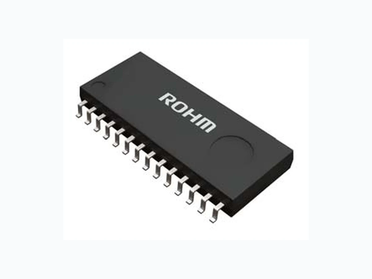
BD9420F ROHM
Document overview
- Manufacturer or author: Provided By www.digicamel.com(FREE DATASHEET DOWNLOAD SITE)
- PDF pages: 31
Technical content
Features
6ch LED constant current driver(External PNP Tr Type) Maximum LED setting current 500mA(VREF Pin setting) ±2% LED current accuracy(VREF=0.9V setting) Built-in DC/DC converter Analog Dimming(Linear) function Built-in PWM-independent soft start circuit LED protection function(OPEN/SHORT protection)[PWM-independent Type] Individual detection and individual LED OFF for both OPEN and SHORT circuit VOUT Over Voltage Protection(OVP) and reduced voltage protection(SCP) circuit Built-in under voltage lockout function(UVLO) and over voltage protection(OVP) Built-in VOUT discharge circuit while shutdown Key Specifications VCC Supply Voltage Range: 9.0V to 35.0V DCDC Oscillation Frequency: 150kHz(RT=100k Ω) Operation Circuit Current: 5mA(Typ) Operating Temperature Range: -40°C to +85°C
Applications
LED driver for TV, Monitor and LCD Back Light Package W(Typ) x D(Typ) x H(Max) SOP28 18.50mm x 9.90mm x 2.41mm Pin Pitch 1.27mm Typical Application Circuit Figure 1. SOP28
TSZ02201-0F1F0C100300-1-2© 2013 ROHM Co., Ltd. All rights reserved. the absolute maximum ratings. Figure 3. Pin Configuration Figure 4. Physical Dimension
TSZ02201-0F1F0C100300-1-2© 2013 ROHM Co., Ltd. All rights reserved. 31.Jan.2014 Rev.002 www.rohm.com TSZ22111 • 15 • 001 BD9420F Electrical Characteristics(Unless otherwise specified VCC=24V Ta=25°C) Parameter Symbol Limit Unit Condition Min. Typ. Max. [Whole Device] Operation Current ICC - 5 10 mA VSTB=3V Standby Current IST - 40 80 uA VSTB=0V [UVLO Block] Operation Voltage (VCC) VUVLO_VCC 6.5 7.5 8.5 V VCC=SWEEP UP Hysteresis Voltage (VCC) VUHYS_VCC 150 300 600 mV VCC=SWEEP DOWN [DC/DC Block] Error amp Base Voltage VEAMP 0.55 0.60 0.65 V BSx pin, VREF=0.9V Oscillation Frequency FCT 142.5 150.0 157.5 kHz RT=100k Ω N Pin MAX DUTY Output NMAX_DUTY 90 95 99 % RT=100k Ω N Pin Source ON Resistance RNSO 2.5 5 10 Ω N Pin Sink ON Resistance RNSI 2 4 8 Ω RT Pin Voltage VRT 1.60 2.00 2.40 V RT=100k Ω RT Short Protection Range RT_DET -0.3 - VRTx90% V RT=SWEEP DOWN RT Pin Low Resistance RRT_L - 2.0 4.0 k Ω VSTB=0V FB Pin Source Current IFBSO -115 -100 -85 uA VBSx=0V, VREF=0.9V, VFB=1.0V FB Pin Sink Current IFBSI 85 100 115 uA VBSx=2.0V, VREF=0.9V, VFB=1.0V Over Current Detect Voltage VCS 0.35 0.40 0.45 V CS=SWEEP UP CS Source Current ICS 15 30 60 uA VCS=0V [DC/DC Protection Block] OVP High Detect Voltage VOVPH 2.88 3.00 3.12 V VOVP SWEEP UP OVP Hysteresis Voltage VOVPH_HYS 150 200 250 V VOVP SWEEP DOWN Short Protection Detect Voltage VSCP 0.05 0.10 0.15 V VOVP SWEEP DOWN OVP Pin Leakage Current OVP_LK -2 0 2 uA VOVP=4V [LED PNP Driver Block] CL Pin Current Setting Voltage VCL 294.0 300.0 306.0 mV VREF=0.9V CL Pin Current Setting Voltage (Analog MAX) VCLMAX -3% 1.0 +3% V VREF max=3.0V CL Pin Current Setting Voltage (Analog MIN) VCLMIN -3% 200.0 +3% mV VREF min=0.6V PNP Driver Output Sink Resistance RBS 55 80 120 Ω PWM=High, VCL=Low VREF Pin Leakage Current VREF_LK -2 0 2 uA VREF=1V
TSZ02201-0F1F0C100300-1-2© 2013 ROHM Co., Ltd. All rights reserved. 31.Jan.2014 Rev.002 www.rohm.com TSZ22111 • 15 • 001 BD9420F Electrical Characteristics(Unless otherwise specified VCC=24V Ta=25°C) Parameter Symbol Limit Unit Condition Min. Typ. Max. [LED Protection Block] LED OPEN Detect Voltage VOPEN 0. 05 0.10 0.15 V BSx=SWEEP DOWN LED SHORT Detect Voltage VLSP 8.5 9.0 9.5 V BSx=SWEEP UP, LSP=OPEN CL Pin Low Detect Voltage VCLLVP 0.05 0.10 0.15 V LSP Pin Pull Up Resistance RULSP 930 1550 2170 k Ω LSP=0V LSP Pin Pull Down Resistance RDLSP 270 450 630 k Ω LSP=4V [REG75 Block] REG75 Output Voltage REG75 7.425 7.50 7.575 V Io=0mA REG75 MAX Output Current | IREG75 | 10 - - mA REG75_UVLO Detect Voltage REG75_T H 3.6 4.0 4.4 V REG75=SWEEP DOWN REG75_UVLO Hysteresis REG75_HYS 250 500 750 mV STB=ON->OFF, REG75=SWEEP UP REG75 Discharge Resistance REG 75_DIS 0.65 1.00 1.35 M Ω STB=ON->OFF, REG75=7.5V [STB Block] STB Pin High Voltage STBH 2.0 - VCC V STB=SWEEP UP STB Pin Low Voltage STBL -0.3 - 0.8 V STB=SWEEP DOWN STB Pin Pull Down Resistance RSTB 600 1000 1400 k Ω STB=3.0V [PWM Input Block] PWM Pin High Detect Voltage PW M_H 1.5 - 18 V PWM=SWEEP UP PWM Pin Low Detect Voltage PWM _L -0.3 - 0.8 V PWM=SWEEP DOWN PWM Pin Pull Down Resistance RPWM 600 1000 1400 k Ω PWM=3.0V [SEL Input Block] SEL Pin High Detect Voltage SEL_H 1.5 - 18 V SEL=SWEEP UP SEL Pin Low Detect Voltage SEL_L -0.3 - 0.8 V SEL=SWEEP DOWN SEL Pin Pull Down Resistance RSEL 600 1000 1400 k Ω SEL=3.0V
TSZ02201-0F1F0C100300-1-2© 2013 ROHM Co., Ltd. All rights reserved. 31.Jan.2014 Rev.002 www.rohm.com TSZ22111 • 15 • 001 BD9420F Pin Descriptions Pin No. Pin Name Function 1 REG75 7.5V regulator output for N output pin
2 N DC/DC switching output pin
3 PGND Power GND
4 CS DCDC external NMOS current monitor pin
5 SEL PWM select pin
6 FB DCDC phase-compensation pin
7 LSP LED short voltage setting pin
8 VREF LED voltage setting pin
9 BS1 PNP Tr Base connecting pin1
10 BS2 PNP Tr Base connecting pin2
11 BS3 PNP Tr Base connecting pin3
12 BS4 PNP Tr Base connecting pin4
13 BS5 PNP Tr Base connecting pin5
14 BS6 PNP Tr Base connecting pin6
15 CL6 PNP Tr collector ・current detection pin6
16 CL5 PNP Tr collector ・current detection pin5
17 CL4 PNP Tr collector ・current detection pin4
18 CL3 PNP Tr collector ・current detection pin3
19 CL2 PNP Tr collector ・current detection pin2
20 CL1 PNP Tr collector ・current detection pin1
21 PWMC Dimming signal input pin C
22 PWMB Dimming signal input pin B
23 PWMA Dimming signal input pin A
24 OVP Overvoltage protection detection pin
25 RT DCDC frequency setting resistor connection pin
26 AGND Analog GND
27 STB Enable pin
28 VCC Power supply pin
TSZ02201-0F1F0C100300-1-2© 2013 ROHM Co., Ltd. All rights reserved. Figure 5. Blockdiagram
TSZ02201-0F1F0C100300-1-2© 2013 ROHM Co., Ltd. All rights reserved. Figure 6. Pin ESD Type
TSZ02201-0F1F0C100300-1-2© 2013 ROHM Co., Ltd. All rights reserved. 31.Jan.2014 Rev.002 www.rohm.com TSZ22111 • 15 • 001 BD9420F Description of pin function P in 1: REG75 The REG pin is used in the DC/DC converter driver block to output 7.5V power. The maximum operating current is 10mA. Using the REG pin at a current higher than 10mA can affect the N pin output pulse, caus ing the IC to malfunction and leading to heat generation of the IC itself . To avoid this problem, it is recommended to make load setting to the minimum level. Pin 2:N The N pin is used to output power to the external NMOS gate driver for the DC/DC converter in the amplitude range of approx. 0 to 7.5V. Frequency setting can be made with a resist or connected to the RT pin. For details of frequency setting, refer to the description of the <RT pin>. Pin 3: PGND The PGND pin is a power ground pin for the driver block of the N output pin. Pin 4: CS CS pin is current detect for DC/DC current mode inductor current control pin. Current flowing through the inductor is conv erted into voltage by the current sensing resistor RCS connected to the CS pin and this voltage is compared with voltage set with the error amplifier to control the DC/DC output voltage. The CS pin also incorporates the overcu rrent protection (OCP) functi on. If the CS pin voltage reaches 0.4V (Typ.) or more, switching operation will be forcedly stopped. Pin 5: SEL SEL pin is PWM control select pin. The PWM control mode is switched according to voltages input in the SEL pin. Avoid using the SEL pin between two states (0.8 to 1.5V). SEL Voltage State SEL= 1.5V~18.0V PWMA → CH1,CH2 common mode control PWMB → CH3,CH4 common mode control PWMC → CH5,CH6 common mode control SEL= -0.3V~0.8V PWMA → CH1,CH2,CH3 common mode control PWMB → no use PWMC → CH4,CH5,CH6 common mode control Pin 6: FB Current mode control DC/DC converter error amplifier output pin. By monitoring voltage of BS (1~6)pin, the highest Vf of LED column will set 2/3(typ.) of applied VREF voltage to BS pin voltage to control inductor current. The phase compensation setting has described separately. In addition, PWM pin will become High Impedance when all PWM signals are in low state, and will maintain FB voltage. Pin 7: LSP LED Short detect voltage setting pin. When LSP=OPEN, LSP pin voltage is 0.9V( typ), the BSx pin of LED SHORT detect voltage is set to 9V. The 10 times of LSP pin voltage is the BSx pin LED SHORT protection detect voltage. Please set LSP pin input voltage range from 0.3V~2.5V. Pin 8: VREF LED current setting pin.1/3(typ) of applied voltage to VREF pin will be LED current feedback voltage, 2/3(typ.) of its voltage will be DCDC feedback voltage (the lowest BSx pin feedback voltage). Basically, because high accuracy of resistor divider is inputted to VREF pin externally, the IC internally will be OPEN (High Impedance )state. Please use external power to design it. It cannot be used in OPEN state. Pin 9-14: BS1-BS6 LED DRIVER output pin. Please connect to Base Terminal of external PNP Tr. Pin 15-20: CL6 – CL1 LED current detect pin. By monitoring vo ltage of CLx pin to detect LED current. Please connect resistor to collector pin of external PNP Tr.
TSZ02201-0F1F0C100300-1-2© 2013 ROHM Co., Ltd. All rights reserved. 31.Jan.2014 Rev.002 www.rohm.com TSZ22111 • 15 • 001 BD9420F Pin 21-23: PWMC, PWMB, PWMA ON/OFF terminal of LED driver pin. It inputs PWM dimming signal directly to adjust output DUTY dimming. For details of PWM control state, refer to the description of the <SEL pin>. High/Low level of PWM terminal is shown as follows: State PWM Voltage LED ON state PWM= 1.5V~18.0V LED OFF state PWM= -0.3V ~0.8V Pin 24: OVP The OVP pin is an input pin for overvoltage protection and short circuit protection of DC/DC output voltage. When voltage of it over 3.0V or higher, CP counting start. When OVP pin voltage<0.1V (typ.) or lower, short circuit protec tion (SCP) function is activated, and output of Gate driver will become low immediately. Pin 25: RT RT sets charge/discharge current determining frequency inside IC. Only a resistor connected to RT determines saw-tooth wave frequency inside IC. When RT=100kΩ,Frequency=150kHz(typ.). For calculation example, please refer to section in “P15 – DC/DC drive frequency setting”. When it reaches under VRT×0.90V(typ), DCDC operation will be stopped in order to prevent from high speed oscillation when the RT resistance is shorted to GND. And when RT pin returns to normal state, DCDC also returns to operation. Pin 26: AGND GND pin for analog system inside IC. Pin 27: STB ON/OFF setting pin and allowed for use to reset the IC from shutdown. ※The IC state is switched (i.e., The IC is switched between ON and OFF state) according to voltages input in the STB pin. Avoid using the STB pin between two states (0.8 to 2.0V). Pin 28: VCC Power source pin of IC, which should be input in the range of 9 – 35 V.
TSZ02201-0F1F0C100300-1-2© 2013 ROHM Co., Ltd. All rights reserved. 31.Jan.2014 Rev.002 www.rohm.com TSZ22111 • 15 • 001 BD9420F 3 ] [ ] [] [ A I V Vohm R LED VREF CL
- LED current setting (VREF pin, CLx pin) Please decide VREF pin input voltage first. When Analog dimming is performed, please be noted that VREF pin input voltage range is (0.6V ~ 3.0V), and decide the input voltage in normal operation. Basically, if VREF pin voltage is high, it will cause power dissipation of external PNP Tr become high, so it is preferred to set the VREF pin voltage lower. Later, VREF=0.9V will be set as basic. For example if you create 0.9V from REG75, it is possible to use resistive divider by setting 88kohm and 12kohm. The LED current detection is performed by CLx pin. CLx pin is controlled so that the voltage of 1/3V(typ.) of VREF voltage. If VREF=0.9V, CLx=0.3V to control external PNP Tr. Therefore, if 「RCL」 is set as a resistance which between CLx pin and GND, and VREF pin voltage is set as 「VVREF」, LED current 「ILED」can be calculated as below. For current setting, set at each channel. For this reason, in 1ch~3ch and 4ch~6ch, it is possible to change current by setting 「RCL」value.
- DCDC operation frequency setting (RT Pin) The operation frequency of DCDC output is set by resistance which connected to RT pin. ○The relationship between operation and RT resistance (ideal) Setting Example】 If DCDC frequency is set to be 200kHz, RRT as below: ] [] [ 15000 kkHz fR SW RT ] [ 75] [ 200 15000 ] [ 15000 kkHzkHz fR sw RT Above is an ideal equation which do not putted with correction terms. For accurate frequency setting, please confirm on the real system. But the frequency setting range is 100kHz~800kHz. Here, fsw=DCDC converter oscillation frequency[kHz]
TSZ02201-0F1F0C100300-1-2© 2013 ROHM Co., Ltd. All rights reserved. 31.Jan.2014 Rev.002 www.rohm.com TSZ22111 • 15 • 001 BD9420F
- Maximum DCDC output Voltage In this IC, the voltage of BSx pin is depending on VREF pin voltage. The maximum voltage of VREF pin (VREF=3.0V), the voltage of BSx pin will become 2.0V(2/3 of VREF voltage ). The maximum voltage of DCDC output will have be vary with 1.6V while Analog dimming is performed (2/3 of 3.0V - 0.6V).
- Soft Start Time setting This IC have a built in soft start time setting, there is no need to change from the outside. Timer time can be set by counting the clock frequency with RT pin. Starts counting when shutdown function terminal STB etc is released, and start time are considered in the count (in soft -start). Therefore, LED OPEN protection ・SHORT protection are not detected during this time. The soft start time is set inside the IC, as the following equation. (Please note that soft-start time set here is the mask of the running time and not the time until the output stabilizes of the DCDC. Time to stabilize the output or load is greater than the boost DCDC dependent.) Soft-start time "TSS", RT pin connection resistor "RRT" : Start-up sequence The following describes the start-up sequence of this IC. ○Description of start-up sequence ①Set STB from Low to High ②System will be activated while PWM=H. SS counting start. At this time, a circuit in which internal SS voltage for slow start becomes equal to FB pin voltage operates to equalize the FB pin and internal SS voltages regardless of whether the PWM pin is set to Low or High level. ③Since the FB pin and internal SS reach the lower limit of the internal sawtooth wave of the IC, the DC/DC converter operates to start VOUT voltage rising. ④The Vout voltage continues rising to reach a voltage at which LED current starts flowing. ⑤When the LED current reaches the amount of current, isolate the FB circuit from the SS circuit. With this, the startup operation is completed. ⑥After that, normal operation is controlled by following the feedback voltage of LED pins. If the SS pin voltage reaches 4V or higher, the LED protection function will be activated to forcedly end the SS and FB equalizing circuit. 1010 5 . 1 ] [12480[sec] RT SS RT STB Internal SS SLOPE PWM N VOUT ILED LED_OK FB OSC
TSZ02201-0F1F0C100300-1-2© 2013 ROHM Co., Ltd. All rights reserved. 31.Jan.2014 Rev.002 www.rohm.com TSZ22111 • 15 • 001 BD9420F
- OVP/SCP setting procedure (OVP Pin) The OVP pin is an input pin for overvoltage protection and short circuit protection of DC/DC output voltage. The OVP pin is a high impedance type and no pull-down resistor inside, resulting in unstable potential in the open circuit state. To avoid this problem, be sure to make input voltage setting with the use of a resistive divider. ○OVP detect setting equation Assuming that voltage of VOUT rising abnormally and detecting OVP is “VOVP DET”, R1 and R2 setting will be made by the following equation. ○OVP release setting equation When R1 and R2 setting is determined by the equation shown above, OVP release voltage VOVP CAN will be give by the following equation : ○SCP detect setting The SCP setting「VSCPDET」 voltage is calculated as below when R1,R2 is decided above: ] [] [ 2 k R k RVVSCPDET OVP VOUT 3.0V/2.8V- 0.1V
TSZ02201-0F1F0C100300-1-2© 2013 ROHM Co., Ltd. All rights reserved. 31.Jan.2014 Rev.002 www.rohm.com TSZ22111 • 15 • 001 BD9420F ] [] [ V VLEDV V short LSP
- LED short voltage setting(BSx pin, LSP pin) The detection voltage of LED short when BSx pin higher than 9V while LSP pin is in OPEN state. It is possible to change the LED short detection voltage, please input (0.3V~2.5V) to LSP pin. The relationship between LED short detection voltage 「VLEDshort」, and LSP pin voltage 「VLSP」 as below equation. In addition, because LSP pin has split 4V of terminal resistance inside IC. (Refer to upper right schematic ), it will be combined resistance value of IC’s internal resistance and connecting to external resistor. For this reason, when configure the voltage of LSP in resistor divider, it is recommended to connect a resistor which has a little impact from internal resistance value. (Resistance is less susceptible to internal resistor, but care must be taken because power consumption will become large. ) ○LSP setting procedure Below equation shows how to calculate the detection voltage of VLSP by using R1,R2 resistor divide which connect to REG50 voltage. However, this equation is without considering IC resistance. If internal resistance is taken into account, the detection voltage VLSP will be given by the following equation: Please set R1 and R2 resistance so that a difference between resistance values found by Equations (1) and (2) will come to approximately 2% or less as a reference. 【Setting example】 Assuming that LSP is approximated by Equation (1) in order to set LSP detection voltage to 5V, R1 comes to 51k and R2 comes to 3.6k. When calculating LSP detection voltage taking into account internal IC resistance by Equation (2), it will be given as: The difference is given as: As a result, this setting will be little affected by internal impedance. ※For the selection of DC/DC components, please also consider the inaccuracy of each componentts. ] [ 1 ] [ 3 ] [ 50 ] [ 4 ] [ 2 Vk R k R k R k R R R k R k R k R V REF R V REG k R k RVLSP
TSZ02201-0F1F0C100300-1-2© 2013 ROHM Co., Ltd. All rights reserved. 31.Jan.2014 Rev.002 www.rohm.com TSZ22111 • 15 • 001 BD9420F
- Selection of DC/DC Components OCP setting / DCDC component current tolerance selection guide The OCP detection function that is one of the functions of the CS pin will stop the DC/DC converter operating if the CS pin voltage becomes larger than 0.4V.Consequently, it is needed to calculate a peak current flowing through the coil L and then review the resistance of RCS. Furthermore, a current tolerance for DC/DC components should be larger than that for peak current flowing through the coil L. The following describes the peak coil current calculation procedure, CS pin connection resistor RCS selection procedure, and DC/DC component current tolerance selection procedure . ○Peak coil current Ipeak calculation Ripple voltage generated at the CS pin is determined by conditions for DC/DC application components first, Assuming the conditions as below: 「output voltage=VOUT[V] 」 「LED total current=IOUT[A] 」 「DCDC input voltage=VIN[V] 」 「DCDC efficiency=η[%] 」 And then mean input current IIN required for the whole system is given by the following equation. Further, according to drive operation with the DC/DC converter switching frequency fsw [Hz], inductor ripple current ΔIL [A] generated at the inductor L (or H) is given by the following equation. As a result, the peak current Ipeak of IL is given by the following equation. ○CS pin connection resistor RCS selection procedure The current Ipeak flows into RCS to generate voltage. (See the timing chart shown to the right )The voltage VCSpeak is given by the following equation. If VCSpeak voltage reaches 0.4V, DC/DC output will stop.Consequently, to select RCS resistance, the following condition should be met. ○DC/DC component current tolerance selection procedure Iocp current needed for OCP detection voltage CS to reach 0.4V is given by the following equation: The relation among Ipeak current (Equation (1)), Iocp current (Equation (2)), and Maximum current tolerance for component should meet the following equation. DC/DC application components including FETs, inductors, and diodes should be selected so that the Equation shown above will be met. In addition, it is recommended to use continuous mode in DCDC application. And the lower limit value of coil ripples current Imin so as to meet the following equation: A failure to meet this condition is referred to as discontinuous mode and this failure may result in an inadequate rise in output voltage. ] [[%] ] [ ] [ ] [AV V A I V VI IN OUTOUT IN ] [] [ ] [ ] [ ] [ ]) [ ] [ (AHz f V V H L V V V V V VIL SWOUT ININOUT Δ ) 1 ( ] [2 ] [] [ AA ILA I IpeakIN 0 ] [2 ] [] [ min AA ILA I IIN ] [V Ipeak RcsVCS peak OCPpeak I I MAX current tolerance ) 2 ( ] [] [ ] [ 4 . 0ARcs VIOCP ] [ 4 . 0 ] [V V Ipeak Rcs VIN VOUT N CS PGND Rcs IL L IOUT(total) fsw
TSZ02201-0F1F0C100300-1-2© 2013 ROHM Co., Ltd. All rights reserved. 31.Jan.2014 Rev.002 www.rohm.com TSZ22111 • 15 • 001 BD9420F 【Setting example】 Output=VOUT[V]=40V LED 1ch current=120mA, total LED current IOUT[A]=120mA×6ch=0.72A DCDC input voltage=VIN [V] =24V DCDC efficiency=η[%]=90% Mean input current IIN required for the whole system is given by the following equation: DCDC switching frequency=fsw[Hz]=200kHz Inductor [H]=33μH The inductor ripple current ΔIL [A] is given by the following equation: As a result, the peak current Ipeak of IL is given by the following equation. When RCS resistance is set to 0.1ohm, the VCS peak voltage will be given by the following equation: Consequently, the result meets the condition. Furthermore, IOCP current at which OCP is detected is given by the following equation: So must select the component of about 5A in order to meet the above result. Particularly, To select DC/DC components, give consideration to IC variations as well as individual component variations, and then conduct thorough verification on practical systems.. The lower limit value of coil ripple current Imin is given by the following equation, the component will not be put into discontinuous mode. ※For the selection of DC/DC components, please also consider the inaccuracy of each componentts. ] [ 45 . 1] [ 10 200 ] [ 40 ] [ 10 33 ] [ ] [ ] [ ] [ ]) [ ] [ (
36 AHzV H
Δ ] [ 0 . 4] [ 1 . 0 ] [ 4 . 0 AVIOCP OCPpeak I I Max. Current tolerance for component ] [] [min A A A AAILA I IIN
TSZ02201-0F1F0C100300-1-2© 2013 ROHM Co., Ltd. All rights reserved. 31.Jan.2014 Rev.002 www.rohm.com TSZ22111 • 15 • 001 BD9420F ○Selection of inductor L The value of inductor has significant influence on the input ripple current. As shown by Equation (1), the larger the inductor and the higher the switching frequency, the inductor ripple current ∆IL becomes increasingly lower. V V VIL SWOUT ININOUT Expressing efficiency as shown by Equation (2), peak input current is given as Equation (3). IN IN OUTOUT I V I V V I VILI IL IN OUTOUT INMAX Here, L:Inductor value[H] V OUT:DC/DC output voltage[V] VIN:input voltage[V] I OUT:output total current[A] IIN:input current[A] F SW:Oscillation frequency[Hz] Basically, make setting of ∆IL to approximately 30% to 50% of the output load current. ※ If a current in excess of the rated current of the inductor applies to the coil, the inductor will cause magnetic saturation, resulting in efficiency degradation. Select an inductor with an adequate margin so that peak current will not exceed the rated current of the inductor. ※ To reduce power dissipation from and increase efficiency of inductor, select an inductor with low resistance component (DCR or ACR). ○Selection of output capacitor COUT Select a capacitor on the output side taki ng into account the stability region of output voltage and equivalent series resistance necessary to smooth ripple voltage. Note that higher output ripple voltage may result in a drop in LED pin voltage, making it impossible to supply set LED current. The output ripple voltage ∆V OUT is given by Equation (4). I CR ILMAXV SW OUT OUT Here, RESR Equivalent series resistance of COUT. ※ Select capacitor ratings with an adequate margin for output voltage. ※ To use an electrolytic capacitor, an adequate margin should be provided for permissible current. Particularly to apply PWM light modulation to LED, note that a current higher than the set LED current transiently flows. ΔIL VOUT VIN COUT RCS L IL VOUT VIN COUT RCS L RESR IL
TSZ02201-0F1F0C100300-1-2© 2013 ROHM Co., Ltd. All rights reserved. 31.Jan.2014 Rev.002 www.rohm.com TSZ22111 • 15 • 001 BD9420F ○Selection of switching MOSFET transistors There will be no problem for switching MOSFET transistors having absolute maximum rating higher than rated current of the inductor L and VF higher than “COUT breakdown voltage Rectifier diode”. However, to achieve high-speed switching, select transistors with small gate capacity (injected charge amount). Note: Rated current larger than overcurrent protection setting current is recommended. Note: Selecting transistors with low on resistance can obtain high efficiency. ○Selection of rectifier diodes Select Schottky barrier diodes having current capability higher than the rated current of the inductor L and inverse breakdown voltage higher that COUT breakdown voltage, particularly having low forward voltage VF. ○Selection of Load switch MOSFET and soft start function In usual DC/DC converter, because there is no switching to a path leading from VIN to VOUT resulting in output voltage is also occur even if IC is in OFF state.Please insert PMOSFET between VIN and inductor if you want voltage to 0V until the IC starts to operate.In addition, FAIL pin can be used for driving load switch after confirmed the logic theory, and the breakdown voltage of drain-source needed to be selected larger than VIN. Furthermore, if you would like to make soft start function to load switch, please insert a condenser between Gate and Source.
TSZ02201-0F1F0C100300-1-2© 2013 ROHM Co., Ltd. All rights reserved. 31.Jan.2014 Rev.002 www.rohm.com TSZ22111 • 15 • 001 BD9420F
- Phase Compensation Setting Procedure DC/DC converter application for current mode control includes one each of pole fp (phase delay) by CR filer consisting of output capacitor and output resistor (i.e., LED current) and zero (phase lead) fZ by the output capacitor and capacitor ESR. Furthermore, the step-up DC/DC converter includes RHP zero “fZRHP” as the second zero. Since the RHP zero has phase delay (90) characteristics like the pole, the crossover frequency fc should be set to not more than RHP zero. i. Find Pole f p and RHP zero fZRHP of DC/DC converter. H e r e , = LED Total current[A], ii. Find phase compensation to be inserted to error amplifier.(set f c is 1/5 to fZRHP) Here, iii. Find zero used to compensate ESR (R ESR) of COUT (electrolytic capacitor). ※Even if a ceramic capacitor (RESR of the order of milliohms) for COUT, it is recommended to insert CFB2 for stable operation. To improve transient response, it is necessary to increase RFB1 and reduce CFB1. However, this improvement reduces a phase margin. To avoid this problem, conduct thorough verification, including variations in external components, on practical systems. VOUT VIN COUTRCS L RESR ] [2 ) 1 (2 HzI L DVf LED OUT ZRHP ] [) 1 (5 DV gm f I R fR OUTp LEDCSRHZP FB ] [2
1 Ff RC
] [ 2 FR C RC FB OUTESR FB ] [2 HzC V If OUTOUT LED p OUT INOUT V V VD LEDI CFB1 FB RFB1 gm VOUT ILED CFB2
TSZ02201-0F1F0C100300-1-2© 2013 ROHM Co., Ltd. All rights reserved. 31.Jan.2014 Rev.002 www.rohm.com TSZ22111 • 15 • 001 BD9420F ILED PWM=L :STOP I_discharge
- The setting of REG75 capacity and shutdown procedure VOUT discharge function is built-in this IC when IC is shutdowned, the below decribes the operation sequence. ○Explanation of shutdown sequence ①Set STB pin to “OFF” will stops DC/DC converter and REG75, but LED driver will remain operation. ②Discharge the REG75 pin voltage from 7.5V to 4.0V with 1MΩ. ③The VOUT voltage will be discharged with ILED current and the discharged VOUT voltage is no flow ILED current. ④When REG75 pin voltage will reach 4.0V (Typ.) or less to shut down all systems ○REG75 capacitance setting procedure The shutdown time “TOFF” can be calaulated by the following equation. The longest VOUT discharge time will be obtained when the PWM duty cycle is set to the minimum VOUT. Make REG capacitance setting with an adequate margin so that systems will be shut off after VOUT voltage is fully discharged. Figure 14.Timing chart of shutdown [sec] C 10 628.6] V 4.0[ 7.5[V]In ] 1[M [F] C[V]REG75 [V]REG75In ] [ R [F] C [sec] T REG REG UVLO 0 t
TSZ02201-0F1F0C100300-1-2© 2013 ROHM Co., Ltd. All rights reserved. 31.Jan.2014 Rev.002 www.rohm.com TSZ22111 • 15 • 001 BD9420F
- Timing Chart VCC STB REG75 RT Internal SS FB VOUT PWM 7.5V 2.0V 4.5V 2.0V 4.0V LED OPEN Protect Function LED SHORT OVP SCP OCP disable disable disable disable disable *Under SS term, Not charge CP 0.8V disable disable disable disable disable
TSZ02201-0F1F0C100300-1-2© 2013 ROHM Co., Ltd. All rights reserved. 31.Jan.2014 Rev.002 www.rohm.com TSZ22111 • 15 • 001 BD9420F
- List of Protection Functions ○List of protection detecting condition Protection names Detection Detection condition Release condition Timer Protection type pin Detection pin condition PWM SS LED OPEN BSx BSx < 0.1V H(Pulse over 4CLK) SS>4.0V BSx > 0.1V 215count Latch(Only detected ch) CLx CLx < 0.1V H(Pulse over 4CLK) SS>4.0V CLx > 0.1V LED SHORT BSx BSx > 9V H(Pulse over 4CLK) SS>4.0V BSx < 9V 2 15count Latch(Only detected ch) LED GND SHORT BSx BSx < 0.1V H(Pulse over 4CLK) SS>4.0V BSx > 0.1V 215+27coun t Latch CLx CLx < 0.1V H(Pulse over 4CLK) SS>4.0V CLx > 0.1V RT GND SHORT RT Under RT x90% - - Canceled RT=GND State Immediatel y detect Auto-restart VCC UVLO VCC VCC < 7.2V - - VCC>7.5V Immediatel y detect Auto-restart REG75 UVLO REG75 REG75 < 4.0V - - REG75>4.5V Immediatel y detect Auto-restart OVP OVP OVP>3.0V - - OVP<2.8V 2 18count Latch SCP OVP OVP < 0.1V - - OVP > 0.1V 2 15count Latch OCP CS CS>0.4V - - CS<0.4V Immediatel y detect Pulse by Pulse ・To clear the latch type, STB should be set to “L” once, and then to “H”. ・The count of Timer means “1count=1duty of switching frequency.” ○List of protection detecting operation Protection Functions Operation when the hysteresis type protection is detected DC/DC LED Driver Soft start RT pin LED OPEN Stops operating after CP counting Only detected LED stops operating after CP counting Low after all ch Latch Low after all ch Latch LED SHORT Stops operating after CP counting Only detected LED stops operating after CP counting Low after all ch Latch Low after all ch Latch LED GND SHORT Stops operating after CP counting Stops operating after CP counting Discharge after CP counting Low after CP counting RT GND SHORT Instantaneously stops operating Instantaneously stops operating Not discharged - VCC UVLO Instantaneously stops operating Instantaneously stops operating Discharge Normal operation REG75 UVLO Instantaneously stops operating Instantaneously stops operating Discharge Normal operation OVP Instantaneously stops operating Stops operating after CP counting Discharge after CP counting Low after CP counting SCP N output stops Stops operating after CP counting Discharge after CP counting Low after CP counting OCP Limits duty cycle Normal operation Not discharged Normal operation <Example> Case FOSC=150kHz ○LED OPEN,LED SHORT,SCP 32768count→Latch after 218.5msec ○LED GND SHORT 32896count→Latch after 219.3msec ○OVP 262144count→Latch after 1.748sec ○Soft Start time 12480count→83.2msec
TSZ02201-0F1F0C100300-1-2© 2013 ROHM Co., Ltd. All rights reserved. 31.Jan.2014 Rev.002 www.rohm.com TSZ22111 • 15 • 001 BD9420F ○Timing of Error detection This IC is individual Latch OFF. Therefore, Error detection is every channel. The detection timing of LED OPEN, SHORT and GND SHORT Protection is different with PWM Duty or Timing of Error state as follows: ※Error detection is same timing. ※Error detection is only first Error state channel. ※First Error state channel is Latch OFF. Then, the detection of the following channel can detect whenever the new edge of PWM comes. Finally, all Error state channels are Latch off. (A).Other channels will be in Error states within 4counts of internal CLK. [When PWM=100%] (B).Other channels will be in Error states after 4counts of internal CLK. [When PWM=100%] PWM CL1_Voltage H CL2_Voltage 4CLK CH1_Error_Detect (Internal IC) L 0.3V 0.3V Oscllator (Internal IC) CH2_Error_Detect (Internal IC) Error detect Error no detect (C).Other channels will be in Error states after 4counts of internal CLK. [When except PWM=100%]
TSZ02201-0F1F0C100300-1-2© 2013 ROHM Co., Ltd. All rights reserved. 31.Jan.2014 Rev.002 www.rohm.com TSZ22111 • 15 • 001 BD9420F Operational Notes 1. Reverse Connection of Power Supply Connecting the power supply in reverse polarity can damage the IC. Take precautions against reverse polarity when connecting the power supply, such as mounting an external diode between the power supply and the IC’s power supply terminals. 2. Power Supply Lines Design the PCB layout pattern to provide low impedance supply lines. Separate the ground and supply lines of the digital and analog blocks to prevent noise in the ground and supply lines of the digital block from affecting the analog block. Furthermore, connect a capacitor to ground at all power supply pins. Consider the effect of temperature and aging on the capacitance value when using electrolytic capacitors. 3. Ground Voltage Ensure that no pins are at a voltage below that of the ground pin at any time, even during transient condition. 4. Ground Wiring Pattern When using both small-signal and large-current ground traces , the two ground traces should be routed separately but connected to a single ground at the reference point of the application board to avoid fluctuations in the small-signal ground caused by large currents. Also ensure that the ground traces of external components do not cause variations on the ground voltage. The ground lines must be as short and thick as possible to reduce line impedance. 5. Thermal Consideration Should by any chance the power dissipation rating be exceeded the rise in temperature of the chip may result in deterioration of the properties of the chip. The absolute maximum rating of the Pd stated in this specification is when the IC is mounted on a 70mm x 70mm x 1.6mm glass epoxy board. In case of exceeding this absolute maximum rating, increase the board size and copper area to prevent exceeding the Pd rating. 6. Recommended Operating Conditions These conditions represent a range within which the expected characteristics of the IC can be approximately obtained. The electrical characteristics are guaranteed under the conditions of each parameter. 7. Inrush Current When power is first supplied to the IC, it is possible that the internal logic may be unstable and inrush current may flow instantaneously due to the internal powering sequence and delays, especially if the IC has more than one power supply. Therefore, give special consideration to power coupling capacitance, power wiring, width of ground wiring, and routing of connections. 8. Testing on Application Boards When testing the IC on an application board, connecting a capacitor directly to a low-impedance output pin may subject the IC to stress. Always discharge capacitors completely after each process or step. The IC’s power supply should always be turned off completely before connecting or removing it from the test setup during the inspection process. To prevent damage from static discharge, ground the IC during assembly and use similar precautions during transport and storage. 9. Inter-pin Short and Mounting Errors Ensure that the direction and position are correct when mounting the IC on the PCB. Incorrect mounting may result in damaging the IC. Avoid nearby pins being shorted to each other especially to ground, power supply and output pin. Inter-pin shorts could be due to many reasons such as metal particles, water droplets (in very humid environment) and unintentional solder bridge deposited in between pins during assembly to name a few.
TSZ02201-0F1F0C100300-1-2© 2013 ROHM Co., Ltd. All rights reserved. the power supply or ground line.
- Regarding the Input Pin of the IC
When GND > Pin A and GND > Pin B, the P-N junction operates as a parasitic diode. When GND > Pin B, the P-N junction operates as a parasitic transistor. Figure 15. Example of monolithic IC structure temperature and the decrease in nominal capacitance due to DC bias and others.
- Area of Safe Operation (ASO)
- Thermal Shutdown Circuit(TSD)
TSD threshold, the circuits are automatically restored to normal operation.
- Over Current Protection Circuit (OCP)
not be used in applications characterized by continuous operation or transitioning of the protection circuit. reference to help reading the formal version.
TSZ02201-0F1F0C100300-1-2© 2013 ROHM Co., Ltd. All rights reserved. 31.Jan.2014 Rev.002 www.rohm.com TSZ22111 • 15 • 001 BD9420F
Ordering Information
F:SOP28 Packaging and forming specification XX: Please confirm the formal name t o o u r s a l e s . Physical Dimension, Tape and Reel Information (Unit : mm) SOP28 0.11 0.1 0.3MIN 18.5±0.2 0.15±0.1 7.5±0.2 9.9±0.32.2±0.1 0.4±0.11.27 141 (MAX 18.85 include BURR) ∗ Order quantity needs to be multiple of the minimum quantity. <Tape and Reel information> Embossed carrier tapeTape Quantity Direction of feed The direction is the 1pin of product is at the upper left when you hold reel on the left hand and you pull out the tape on the right hand 1500pcs Direction of feed Reel 1pin
TSZ02201-0F1F0C100300-1-2© 2013 ROHM Co., Ltd. All rights reserved. 31.Jan.2014 Rev.002 www.rohm.com TSZ22111 • 15 • 001 BD9420F
Revision History
11.Nov.2013 001 New Release 31.Jan.2014 002 P15. Timing chart of Timer count add P23. Detection condition add P24. Timing of Error detection add
Notice - GE Rev.002 © 2014 ROHM Co., Ltd. All rights reserved. Notice Precaution on using ROHM Products 1. Our Products are designed and manufac tured for application in ordinary electronic equipments (such as AV equipment, OA equipment, telecommunication equipment, home electroni c appliances, amusement equipment, etc.). If you intend to use our Products in devices requiring ex tremely high reliability (such as medical equipment (Note 1), transport equipment, traffic equipment, aircraft/spacecraft, nuclear power controllers, fuel controllers, car equipment including car accessories, safety devices, etc.) and whose malfunction or failure may cause loss of human life, bodily injury or serious damage to property (“Specific Applications”), please consult with the ROHM sale s representative in advance. Unless otherwise agreed in writing by ROHM in advance, RO HM shall not be in any way responsible or liable for any damages, expenses or losses incurred by you or third parties arising from the use of any ROHM’s Products for Specific Applications. (Note1) Medical Equipment Classification of the Specific Applications JAPAN USA EU CHINA CLASSⅢ CLASSⅢ CLASSⅡb CLASSⅢ CLASSⅣ CLASS Ⅲ 2. ROHM designs and manufactures its Products subject to strict quality control system. However, semiconductor products can fail or malfunction at a certain rate. Please be sure to implement, at your own responsibilities, adequate safety measures including but not limited to fail-safe desi gn against the physical injury, damage to any property, which a failure or malfunction of our Products may cause. The following are examples of safety measures: [a] Installation of protection circuits or other protective devices to improve system safety [b] Installation of redundant circuits to reduce the impact of single or multiple circuit failure 3. Our Products are designed and manufactured for use under standard conditions and not under any special or extraordinary environments or conditio ns, as exemplified below. Accordin gly, ROHM shall not be in any way responsible or liable for any damages, expenses or losses arising from the use of an y ROHM’s Products under any special or extraordinary environments or conditions. If you intend to use our Products under any special or extraordinary environments or conditions (as exemplified bel ow), your independent verification and confirmation of product performance, reliability, etc, prior to use, must be necessary: [a] Use of our Products in any types of liquid, including water, oils, chemicals, and organic solvents [b] Use of our Products outdoors or in places where the Products are exposed to direct sunlight or dust [c] Use of our Products in places where the Products ar e exposed to sea wind or corrosive gases, including Cl 2, H2S, NH3, SO2, and NO2 [d] Use of our Products in places where the Products are exposed to static electricity or electromagnetic waves [e] Use of our Products in proximity to heat-producing components, plastic cords, or other flammable items [f] Sealing or coating our Products with resin or other coating materials [g] Use of our Products without cleaning residue of flux (ev en if you use no-clean type fluxes, cleaning residue of flux is recommended); or Washing our Products by using water or water-soluble cleaning agents for cleaning residue after soldering [h] Use of the Products in places subject to dew condensation 4. The Products are not subjec t to radiation-proof design. 5. Please verify and confirm characteristics of the final or mounted products in using the Products. 6. In particular, if a transient load (a large amount of load applied in a short per iod of time, such as pulse. is applied, confirmation of performance characteristics after on-boar d mounting is strongly recomm ended. Avoid applying power exceeding normal rated power; exceeding the power rating under steady-state loading condition may negatively affect product performance and reliability. 7. De-rate Power Dissipation (Pd) depending on Ambient temper ature (Ta). When used in sealed area, confirm the actual ambient temperature. 8. Confirm that operation temperat ure is within the specified range described in the product specification. 9. ROHM shall not be in any way responsible or liable for fa ilure induced under deviant condi tion from what is defined in this document. Precaution for Mounting / Circuit board design 1. When a highly active halogenous (chlori ne, bromine, etc.) flux is used, the residue of flux may negatively affect product performance and reliability. 2. In principle, the reflow soldering method must be used; if flow soldering met hod is preferred, please consult with the ROHM representative in advance. For details, please refer to ROHM Mounting specification
Notice - GE Rev.002 © 2014 ROHM Co., Ltd. All rights reserved. Precautions Regarding Application Examples and External Circuits 1. If change is made to the constant of an external circuit, pl ease allow a sufficient margin c onsidering variations of the characteristics of the Products and external components, including transient characteri stics, as well as static characteristics. 2. You agree that application notes, re ference designs, and associated data and in formation contained in this document are presented only as guidance for Products use. Theref ore, in case you use such information, you are solely responsible for it and you must exercise your own independent verification and judgment in the use of such information contained in this document. ROHM shall not be in any way responsible or liable for any damages, expenses or losses incurred by you or third parties arising from the use of such information. Precaution for Electrostatic This Product is electrostatic sensitive product, which may be damaged due to electrostatic discharge. Please take proper caution in your manufacturing process and storage so that voltage exceeding t he Products maximum rating will not be applied to Products. Please take special care under dry condit ion (e.g. Grounding of human body / equipment / solder iron, isolation from charged objects, setting of Ionizer, friction prevention and temperature / humidity control). Precaution for Storage / Transportation 1. Product performance and soldered connections may deteriora te if the Products are stored in the places where: [a] the Products are exposed to sea winds or corros ive gases, including Cl2, H2S, NH3, SO2, and NO2 [b] the temperature or humidity exceeds those recommended by ROHM [c] the Products are exposed to di rect sunshine or condensation [d] the Products are exposed to high Electrostatic 2. Even under ROHM recommended storage c ondition, solderability of products out of recommended storage time period may be degraded. It is strongly recommended to confirm sol derability before using Products of which storage time is exceeding the recommended storage time period. 3. Store / transport cartons in the co rrect direction, which is indicated on a carton with a symbol. Otherwise bent leads may occur due to excessive stress applied when dropping of a carton. 4. Use Products within the specified time after opening a hum idity barrier bag. Baking is required before using Products of which storage time is exceeding the recommended storage time period. Precaution for Product Label QR code printed on ROHM Products label is for ROHM’s internal use only. Precaution for Disposition When disposing Products please dispose them properly using an authorized industry waste company. Precaution for Foreign Exchange and Foreign Trade act Since our Products might fall under cont rolled goods prescribed by the applicable foreign exchange and foreign trade act, please consult with ROHM representative in case of export. Precaution Regarding Intellectual Property Rights 1. All information and data including but not limited to application example contain ed in this document is for reference only. ROHM does not warrant that foregoi ng information or data will not infringe any intellectual property rights or any other rights of any third party regarding such information or data. ROHM shall not be in any way responsible or liable for infringement of any intellectual property rights or other damages arising from use of such information or data.: 2. No license, expressly or implied, is granted hereby under any intellectual property rights or other rights of ROHM or any third parties with respect to the information contained in this document. Other Precaution 1. This document may not be reprinted or reproduced, in whol e or in part, without prior written consent of ROHM. 2. The Products may not be disassembled, converted, modified, reproduced or otherwise changed without prior written consent of ROHM. 3. In no event shall you use in any wa y whatsoever the Products and the related technical information contained in the Products or this document for any military purposes, incl uding but not limited to, the development of mass-destruction weapons. 4. The proper names of companies or products described in this document are trademarks or registered trademarks of ROHM, its affiliated companies or third parties.
Notice – WE Rev.001 © 2014 ROHM Co., Ltd. All rights reserved. General Precaution 1. Before you use our Pro ducts, you are requested to care fully read this document and fully understand its contents. ROHM shall n ot be in an y way responsible or liabl e for failure, malfunction or acci dent arising from the use of a ny ROHM’s Products against warning, caution or note contained in this document. 2. All information contained in this docume nt is current as of the issuing date and subj ec t to change without any prior notice. Before purchasing or using ROHM’s Products, please confirm the la test information with a ROHM sale s representative. 3. The information contained in this doc ument is provi ded on an “as is” basis and ROHM does not warrant that all information contained in this document is accurate an d/or error-free. ROHM shall not be in an y way responsible or liable for any damages, expenses or losses incurred by you or third parties resulting from inaccuracy or errors of or concerning such information.