
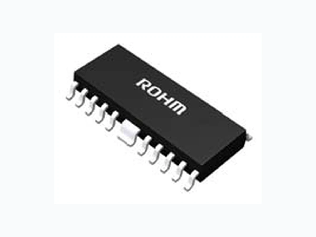
BD93941EFV ROHM
Document overview
- Manufacturer or author: Provided By www.digicamel.com(FREE DATASHEET DOWNLOAD SITE)
- PDF pages: 30
Technical content
TSZ02201-0F1F0C100270-1-2© 2013 ROHM Co., Ltd. All rights reserved. *1 The amount of current per channel. To avoid this problem, design the board with thorough consideration given to heat radiation measures. Figure 3. Pin Configuration
TSZ02201-0F1F0C100270-1-2© 2013 ROHM Co., Ltd. All rights reserved. Figure 4. Physical Dimension
TSZ02201-0F1F0C100270-1-2© 2013 ROHM Co., Ltd. All rights reserved. 10.Oct.2013 Rev.001 www.rohm.com TSZ22111・15・001 BD93941EFV BD93941FP Electrical Characteristics (Unless otherwise noted, Ta = 25oC, VCC=24V) Parameter Symbol Limit Unit Condition Min. Typ. Max. [DC/DC Protection Block] Overvoltage protection detection voltage VOVP 2.7 3.00 3.3 V OVP=SWEEP UP Overvoltage protection detection hysteresis voltage VOVP_HYS 50 100 200 mV OVP=SWEEP DOWN Short circuit protection detection voltage VSCP 0.04 0.10 0.25 V OVP=SWEEP DOWN [LED Driver Block] LED pin current accuracy 1 dILED1 -2 - 2 % ILED=100mA, (ADIM=2.5V,ISET=75kΩ) LED pin current accuracy 2 dILED2 -3.2 - 3.2 % ILED=70mA, (ADIM=1.75V,ISET=75kΩ) LED pin current accuracy 3 dILED3 -4.6 - 4.6 % ILED=50mA, (ADIM=1.25V,ISET=75kΩ) LED pin current accuracy 4 dILED4 -8 - 8 % ILED=30mA, (ADIM=0.75V,ISET=75kΩ) LED pin current accuracy 5 dILED5 -3 - 3 % ILED=100mA, (ADIM=7V,ISET=75kΩ) LED pin Leakage Current ILLED -2.5 - 2.5 μA LED=60V LED open detection voltage VOPEN 0.05 0.2 0.285 V LED=SWEEP DOWN LED short detection voltage VSHORT 4 5 6 V LED=SWEEP UP ADIM pin Input Current ILADIM -2.5 - 2.5 μA ADIM=3V [STB Block] STB pin high-level voltage STBH 2 - 35 V STB=SWEEP UP STB pin low-level voltage STBL -0.3 - 0.8 V STB=SWEEP DOWN STB pin pull-down resistance RSTB 500 1000 1500 k Ω STB=3.0V [PWM Block] PWM pin high-level voltage PWMH 2 - 35 V PWM=SWEEP UP PWM pin low-level voltage PWML -0.3 - 0.8 V PWM= SWEEP DOWN PWM pin pull-down resistance RPWM 180 300 420 k Ω PWM=3.0V [Failure Indication Block (Open Drain)] AUTO pin source current IAUTO -2 -1 -0.5 μA AUTO=2V AUTO pin Detection Voltage VAUTO 3.6 4.0 4.4 V AUTO=SWEEP UP Abnormal Detection Timer tCP 20 ms RT=75k Ω
TSZ02201-0F1F0C100270-1-2© 2013 ROHM Co., Ltd. All rights reserved. 10.Oct.2013 Rev.001 www.rohm.com TSZ22111・15・001 BD93941EFV BD93941FP Pin Descriptions (BD93941EFV) Pin No Pin Name In/Out Function Rating [V] 1 AUTO Out Auto-restart time setting pin -0.3 to 7 2 REG58 Out Power supply for N pin -0.3 to 7 3 CS In DC/DC output current detection and OCP detection pin -0.3 to 7 4 N Out DC/DC switching output pin -0.3 to 7
5 DCDC_GND - Power GND pin -
6 OVP In Overvoltage protection detection pin -0.3 to 36 7 STB In Enable pin -0.3 to 36 8 LED1 Out Output pin 1 for LED -0.3 to 60 9 LED2 Out Output pin 2 for LED -0.3 to 60
10 LED_GND - Ground pin for LED -
11 LED3 Out Output pin 3 for LED -0.3 to 60 12 LED4 Out Output pin 4 for LED -0.3 to 60 13 PWM In External PWM light modulation si gnal input pin for LED1-4 -0.3 to 36 14 ISET Out LED current setting resistor connection pin -0.3 to 7
15 GND - Analog GND pin -
16 SS Out Soft start pin / LED protecti on masking time setting pin. -0.3 to 7 17 FB In/Out Error amp output pin -0.3 to 7 18 RT Out DC/DC drive frequency setting resistor connection pin. -0.3 to 7 19 ADIM In Analog dimming DC voltage input pin -0.3 to 36 20 VCC In Power supply pin -0.3 to 36 Pin Descriptions (BD93941FP) Pin No Pin Name In/Out Function Rating [V] 1 AUTO Out Auto-restart time setting pin -0.3 ~ 7 2 REG58 Out Power supply for N pin -0.3 ~ 7 3 CS In DC/DC output current detection and OCP detection pin -0.3 ~ 7 4 N In DC/DC switching output pin -0.3 ~ 7 6 OVP In Overvoltage protection detection pin -0.3 ~ 36 7 STB In Enable pin -0.3 ~ 36 8 LED1 Out Output pin 1 for LED -0.3 ~ 60 9 LED2 Out Output pin 2 for LED -0.3 ~ 60 11 N.C. - Non connection pin - 12 LED3 Out Output pin 3 for LED -0.3 ~ 60 13 LED4 Out Output pin 4 for LED -0.3 ~ 60 14 PWM In External PWM light modulation signal input pin for LED1-4 -0.3 ~ 36 15 ISET Out LED current setting resistor connection pin -0.3 ~ 7 FIN2 GND - Analog GND pin - 16 SS Out Soft start pin / LED protection masking time setting pin. -0.3 ~ 7 17 FB In/Out Error amp output pin -0.3 ~ 7 18 RT Out DC/DC drive frequency setting resistor connection pin. -0.3 ~ 7 19 ADIM In Analog dimming DC voltage input pin -0.3 ~ 36 20 VCC In Power supply pin -0.3 ~ 36
TSZ02201-0F1F0C100270-1-2© 2013 ROHM Co., Ltd. All rights reserved. Figure 5. Pin ESD Type
TSZ02201-0F1F0C100270-1-2© 2013 ROHM Co., Ltd. All rights reserved. Figure 6. Block Diagram
TSZ02201-0F1F0C100270-1-2© 2013 ROHM Co., Ltd. All rights reserved. 10.Oct.2013 Rev.001 www.rohm.com TSZ22111・15・001 BD93941EFV BD93941FP Pin Function ○AUTO (1pin) This sets up time till auto-restart time from the point of abnormal detection. Having 1 μA constant current charge at external capacitor connected to AUTO pin, it will start again when it becom es over 4.0V (The auto pin is shorted to GND, this IC’s protection function operates latched off mode). ○Auto-restart period vs. AUTO capacitance (Ideal) ○REG58 (2pin) The REG58 pin is used in the DC/DC converter driver block to output 5.8V power. The maximum operating current is 15mA. Using the REG58 pin at a curr ent higher than 15mA can affect the N pin out put pulse, causing the IC to malfunction and leading to heat generation of the IC itself. To avoid this pr oblem, it is recommended to make load setting to the minimum level. Please place the ceramic capacitor connected to REG58 pin (2.2μF~10μF) closest to REG58-GND pin. ○CS (3pin) The CS pin has the following two functions: 1. DC/DC current mode current feedback function Current flowing through the inductor is conv erted into voltage by the current sensi ng resistor RCS connected to the CS pin and this voltage is compared with voltage set with the error amplifier to control the DC/DC output voltage. 2. Inductor current limit function The CS pin also incorporates the over current protection (OCP) function. If the CS pin voltage reaches 0.45V (Typ.) or more, switching operation will be forcedly stopped. ○N (4pin) The N pin is used to output power to the external NMOS gate driver for the DC/DC converte r in the amplitude range of Frequency setting can be made with a resistor connected to t he RT pin. For details of frequency setting, refer to the description of the RT pin. ○DCDC_GND (5pin) The PGND pin is a power ground pin for the driver block of the output pin N. ○OVP (6pin) The OVP pin is an input pin for over-voltage protection and short circuit protection of DC/DC output voltage. If over-voltage is detected, the OVP pin will stop the DC/DC converter conduc ting step-up operation. When the short circuit protection (SCP) function is activated, the DC/DC co nverter will stop operation, and then the timer will start counting. When the timer completes counting the preset period of time, the LED drivers are stopped. The OVP pin is of the high impedance type and involves no pu ll-down resistor, resulting in unstable potential in the open-circuited state. To avoid this problem, be sure to make input voltage setting with the use of a resistive divider or otherwise. ○STB (7pin) The STB pin is used to make setting of turning ON and OFF the IC and allowed for use to reset the IC from shutdown. Note: The IC state is switched (i.e., the IC is switched bet ween ON and OFF state) according to voltages input in the STB pin. Avoid using the STB pin between two states (0.8 to 2.0V). ○LED1 – LED4 (8,9,11,12pin) The LED1 to 4 pins are used to output co nstant current to LED drivers. Current value setting can be made by connecting a resistor to the ISET pin. For the current value setting procedure, refer to the description of “ISET pin”. If any of the LED pins is put in an erroneous state (e.g. short circuit mode, open circuit mode, or ground short circuit mode), the relevant protection function will be activated. ○LED_GND (10pin) The LED_GND pin is a power ground pin used for the LED driver block. ○PWM (13pin) The PWM pin is used to turn ON and OFF LED drivers. Light c an be modulated by changing the duty cycle through the direct input of a PWM light modulation signal. The high and low voltage levels of PWM pin is as listed in the table below: State PWM Voltage LED ON state PWM= 2.0V to 35V LED OFF state PWM= -0.3V to 0.8V [sec]10 0 . 4 ] [ 10 0 . 1 ] [ 0 . 4 6
6 AUTO
A C VT
TSZ02201-0F1F0C100270-1-2© 2013 ROHM Co., Ltd. All rights reserved. 10.Oct.2013 Rev.001 www.rohm.com TSZ22111・15・001 BD93941EFV BD93941FP ○ISET (14pin) The ISET pin is an output current setting resistor. Output current ILED varies in inverse proportion to resistance. The relation between output current ILED and the resistance of ISET pin connection resistor RISET is given by the following equation: ( A D I M = 0 . 2 V t o 2 . 7 V ) ( A D I M > 4 V t o 3 5 V ) Output current setting should be made in the range of 30 to 200mA. It prepares automatically to suitable LED feedback vo ltage that can output LED current set by ISET pin. In short LED feedback voltage is dropped when the LED current is small and the IC heating is held automatically. In case of a large current is needed, raise the LED pin feedba ck voltage. And it adjusts automatically to LED pin voltage that can be flow large LED current. The calculation is as below. The LED feedback voltage (VLED) is clamped to 0.3V (typ.) when the LED current (ILED) is less than 81.1mA. ADIM input range is from 0V to 35V. And the range which the LED currents change with linearity is from 0.2V to 2.7V. When it reaches under VISET×0.90V(typ.), t he LED current is off to prevent from passing a large current to the LED pin when the RISET is shorted and the ISET pin is shorted to the GND. And as the ISET pin returns to a normal state, the LED current returns. ○GND (15pin) The GND pin is an internal analog circuit ground of the IC. ○SS (16pin) The SS pin is used to make setting of soft start time and duty fo r soft start. It performs constant current charge of 2.0 uA to the external capacitor connected with SS terminal, which enables soft-start of DC/DC converter. Since the LED protection function (OPEN/S HORT detection) works when the SS termi nal voltage reaches 3.7 V (typ.) or higher, it must be set to bring stability to conditions such as DC/DC output voltage and LED constant current drive operation, etc. before the voltage of 3.7 V is detected. ○FB (17pin) The FB pin is an output pin used for DC/DC current mode control error amplifier. In other words, the FB pin detects the voltages of LED pins (1 to 4) and controls inductor current so that the pin voltage of the LE D located in the row with the highest Vf will come to 0.37V (ADIM=2.5V, ILED=100mA). As a result, the pin voltages of other LEDs become higher by Vf variation. After completion of soft start, the FB pin is put into the high-impedance state with the PWM signal being in the low state, thus maintaining the FB voltage. ○RT (18pin) The RT pin is used to connect a DC/DC frequency setting resist or. DC/DC drive frequency is determined by connecting the RT resistor. Drive frequency vs. RT resistance (Ideal) When RT is 100kΩ, Fsw is 150kHz(typ.). However, drive frequency setti ng should be made in the range of 100 kHz to 800 kHz. ○ADIM (19pin) ADIM pin is for analog dimming. Output current is proporti onality with input voltage. Basically, ADIM pin assumes the voltage inputted externally using high accuracy of resistive di vider and etc., IC internally is in OPEN (High impedance) condition. Cannot use in an OPEN condition If you don't use analog dimming, please connect pull-up resistor to over 5V (for example REG58). ○VCC (20pin) The VCC pin is used to supply power for the IC in the range of 9 to 35V. be shut down. Ω] [ 7500] [ k RmA I ISET LED Ω ] [] [ 3000] [ V Vk RmA I ADIM ISET LED ] [] [ 15000 kkHz fR SW RT ] [ ] [ 7 . 3V A IVLED LED
TSZ02201-0F1F0C100270-1-2© 2013 ROHM Co., Ltd. All rights reserved. The following section describes the sequence for the startup of this IC. (1) Set the STB and PWM pin to “ON”. (2) Set sll systems to “ON”, SS charge will be initiated. FB pin and SS pin voltages regardless of whether the PWM pin is set to Low or High level. operates to start VOUT voltage rising. (4) The Vout voltage continues rising to reach a voltage at which LED current starts flowing. startup operation is completed. (6) After that, conduct normal operation following the feedback operation sequence with the LED pins. current, output voltage, and others. Make maeasurement of VOUT startup time with a 100% duty cycle, first. Take this value as “Trise100”. The startup time “Trise_min” for the relevant application with the minimum duty cycle is given by the following equation. However, since this calculation method is just for approximation, use it only as a guide. Make setting of time during which the SS pin voltage reaches the FB pin voltage longer than this startup time. Figure 11. Startup waveform Figure 12. Circuit behavior at startup
TSZ02201-0F1F0C100270-1-2© 2013 ROHM Co., Ltd. All rights reserved. ② All systems are ON at initial timing of PWM=H. SS starts charging. unused LED pins are below 0.2V. ⑤ During this time, determination on whether the LED pins are 0.2V above/below is done. ⑥ After the determination, unused LED pins are pulled up to 5V. ⑦The AUTO signal remains “L” level. that the step-up/boost be completed before SS> 3.7V. Figure 14. Block diagram
TSZ02201-0F1F0C100270-1-2© 2013 ROHM Co., Ltd. All rights reserved. 10.Oct.2013 Rev.001 www.rohm.com TSZ22111・15・001 BD93941EFV BD93941FP ] [] [ 15000 kkHz fR SW RT LED current setting Setting of LED output current “ILED” can be made by connecting a resistor RISET to the ISET pin. RISET vs. ILED current relation equation However, LED current setting should be made in the range of 30mA to 200mA. [Setting example] To set ILED current to 100mA, RISET resistance is given by the following equation: DC/DC converter drive frequency setting DC/DC converter drive frequency is determined by making RT resistance setting. Drive frequency vs. RT resistance (ideal) relation equation [Setting example] To set DC/DC drive frequency “fsw” to 200 kHz, RRT is given by the following equation: ] [] [ 7500 kmA IR LED ISET ] [ 75] [ 100 7500 ] [ 7500 kmAmA IR LED ISET where fsw DC/DC converter oscillation frequency [kHz] This equation has become an ideal equation without any correction item included. For accurate frequency settings, thorough verification should be performed on practical sets. ] [ 75] [ 200 15000 ] [ 15000 kkHzkHz fR sw RT (ADIM=2.5V)
TSZ02201-0F1F0C100270-1-2© 2013 ROHM Co., Ltd. All rights reserved. OVP pin is DC/DC output voltage’s over voltage protection and short circuit protection input pin. input settings using voltage dividing resistor and such. and then conduct thorough verification on practical systems. Figure 15. OVP/SCP setting example
TSZ02201-0F1F0C100270-1-2© 2013 ROHM Co., Ltd. All rights reserved. When various abnormal conditions happen, counting starts from the timing, latch occurs after below time has passed. Furthermore, even if PWM=L, if abnormal condition continues, timer count will not reset. Figure 16. Example of LED Short protection timing chart
TSZ02201-0F1F0C100270-1-2© 2013 ROHM Co., Ltd. All rights reserved. 10.Oct.2013 Rev.001 www.rohm.com TSZ22111・15・001 BD93941EFV BD93941FP 【Setting Example】 Output voltage=VOUT[V]=56V LED total current=IOUT[A]=100mA×4ch=0.40A DCDC input voltage=VIN[V]=14V DCDC efficiency=η[%]=90% Total required average input current IIN: When, DCDC switching frequency =fsw[Hz]=200kHz Inductor L[H]=33uH, Inductor ripple current ΔIL[A]: Thus, IL peak current Ipeak becomes RCS resistor value when set at 0.1ohm and satisfy the condition. In addition、OCP detection current I OCP at this time is If parts used (FET,INDUCTOR、DIODE etc)’s current capacity<5A, Thus, there is no problem of parts selection as the above condition is satisfied. In addition、IL ripple current minimum limit Imin is Thus、will not become discontinuous mode。 To select DC/DC components, give consideration to IC variations as well as individual component variations, and then conduct thorough verification on practical systems. ] [ 40 . 0 ] [ 56 [%] ] [ ] [ ] [] [ AV A V V V A I V VA I IN OUTOUT IN ] [ 59 . 1] [ 10 200 ] [ 56 ] [ 10 33 ] [ ] [ ] [ ] [ ]) [ ] [ (
36 AHzV H
Δ ] [ 58 . 22 ] [] [ AAA AA ILA I IpeakIN ] [] [ Im AAA AA ILA I inIN V VAIpeak RcsVCS peak 45 . 0 ] [ 258 . 0 ] [ 58 . 2 ] [ 10 . 0 ] [ 5 . 4] [ 1 . 0 ] [ 45 . 0AVIOCP OCPpeak I I Rated current of components ] [ 5 ] [ 5 . 4 ] [ 58 . 2A A A …Peak current calculation result …RCS resistor consideration …DCDC current capacity consideration
TSZ02201-0F1F0C100270-1-2© 2013 ROHM Co., Ltd. All rights reserved. capacitor and output resistor (i.e., LED current) and zero (phase lead) fZ by the output capacitor and capacitor ESR. i. Find pole f p and RHP zero fZRHP of DC/DC converter. ESR) of COUT (electrolytic capacitor).
1 Ff Rf RC
Figure 21. Output stage and error amplifier diagram
TSZ02201-0F1F0C100270-1-2© 2013 ROHM Co., Ltd. All rights reserved. Figure 22. Timing chart
TSZ02201-0F1F0C100270-1-2© 2013 ROHM Co., Ltd. All rights reserved. 10.Oct.2013 Rev.001 www.rohm.com TSZ22111・15・001 BD93941EFV BD93941FP List of Protect Function (typ condition) Protection Name Detection Pin Detection Conditions Cancellation Conditions Protection Type Detection pin PWM SS LED OPEN LEDx LEDx < 0.2V H SS>3.7V LEDx > 0.2V Immediately Auto-Restart after detection (Judge periodically whether normal or not) LEDSHORT LEDx LEDx > 5V H SS>3.7V LEDx < 5V Immediately Auto-Restart after detection (Judge periodically whether normal or not) ISET GND SHORT ISET Under - - Above Auto-Restart ISET×90% ISET×90% REG58 UVLO REG58 REG58<2.4V - - REG58>2.6V Auto-Restart VCC UVLO VCC VCC<7.3V - - VCC>7.5V Auto-Restart OVP OVP OVP>3.0V - - OVP<2.9V Auto-Restart SCP OVP OVP<0.1V - - OVP>0.1V Immediately Auto-Restart after detection (Judge periodically whether normal or not) FB OVER SHOOT FB FB>4V - - FB<3.6V Immediately Auto-Restart after detection (Judge periodically whether normal or not) OCP CS OCP>0.45V - - - Pulse-by-Pulse To clear the latch type, STB should be set to “L” once, and then to “H”. Protection Function Operation after the protection function detected DC/DC LED Driver Soft-start LED OPEN Continue to operate Only detects LED, stops after CP1 count Continue to operate LEDSHORT Continue to operate Only detects LED, stops after CP1 count Continue to operate ISET GND SHORT Stop immediately Stop immediately Continue to operate STB Stop immediately Stop (and when REG58<2.4V) Discharge immediately REG58 UVLO Stop immediately Stop immediately Discharge immediately VCC UVLO Stop immediately Stop immediately Discharge immediately OVP Stop immediately (N pin only) Continue to operate Continue to operate SCP Stop immediately (N pin only) Stop after CP1 count Discharge after CP1 count FB OVER SHOOT Stop after CP2 count Stop after CP2 count Continue to operate OCP N pin limits DUTY Continue to operate Continue to operate * CP1 = 20ms (RT=75KΩ) , CP2=1.31s (RT=75KΩ)
TSZ02201-0F1F0C100270-1-2© 2013 ROHM Co., Ltd. All rights reserved. 10.Oct.2013 Rev.001 www.rohm.com TSZ22111・15・001 BD93941EFV BD93941FP Operational Notes 1. Reverse Connection of Power Supply Connecting the power supply in reverse polarity can damage the IC. Take precautions against reverse polarity when connecting the power supply, such as mounting an external diode between the power supply and the IC’s power supply terminals. 2. Power Supply Lines Design the PCB layout pattern to provide low impedance supply lines. Separate the ground and supply lines of the digital and analog blocks to prevent noise in the ground and supply lines of the digital bloc k from affecting the analog block. Furthermore, connect a capacitor to ground at all po wer supply pins. Consider the effect of temperature and aging on the capacitance value when using electrolytic capacitors. 3. Ground Voltage Ensure that no pins are at a voltage below that of the ground pin at any time, even during transient condition. 4. Ground Wiring Pattern When using both small-signal and large-current ground traces, the two ground traces should be routed separately but connected to a single ground at the reference point of the application board to avoid fluctuations in the small-signal ground caused by large currents. Also ensure that the ground trac es of external components do not cause variations on the ground voltage. The ground lines must be as short and thick as possible to reduce line impedance. 5. Thermal Consideration Should by any chance the power dissipation rating be exceed ed the rise in temperature of the chip may result in deterioration of the properties of the ch ip. The absolute maximum rating of the Pd stated in this specification is when the IC is mounted on a 70mm x 70mm x 1.6mm glass epoxy b oard. In case of exceeding this absolute maximum rating, increase the board size and copper area to prevent exceeding the Pd rating. 6. Recommended Operating Conditions These conditions represent a range within which the expected characteristics of the IC can be approximately obtained. The electrical characteristics are guaranteed under the conditions of each parameter. 7. Rush Current When power is first supplied to the IC, it is possible that the internal logic may be unstable and inrush current may flow instantaneously due to the internal powering sequence and delays, especially if the IC has more than one power supply. Therefore, give s pecial consideration to power coupling capacitance, power wiring, width of ground wiring, and routing of connections. 8. Testing on Application Boards When testing the IC on an application board, connecting a capacitor directly to a low-impedance output pin may subject the IC to stress. Always dischar ge capacitors completely after each process or step. The IC’s power supply should always be turned off completely before connecting or removing it from the test setup during the inspection process. To prevent damage from static discharge, ground the IC during assemb ly and use similar precautions during transport and storage. 9. Inter-pin Short and Mounting Errors Ensure that the direction and position are correct when mounting the IC on the PC B. Incorrect mounting may result in damaging the IC. Avoid nearby pins being shorted to each other especially to ground, power supply and output pin. Inter-pin shorts could be due to many reasons such as metal particles, water droplets (in very humid environment) and unintentional solder bridge deposited in between pins during assembly to name a few.
TSZ02201-0F1F0C100270-1-2© 2013 ROHM Co., Ltd. All rights reserved. the power supply or ground line.
- Regarding the Input Pin of the IC
When GND > Pin A and GND > Pin B, the P-N junction operates as a parasitic diode. When GND > Pin B, the P-N junction operates as a parasitic transistor. Figure 23. Example of monolithic IC structure temperature and the decrease in nominal capacitance due to DC bias and others.
- Area of Safe Operation (ASO)
- Thermal Shutdown Circuit(TSD)
the TSD threshold, the circuits are automatically restored to normal operation.
- Over Current Protection Circuit (OCP)
not be used in applications characterized by continuous operation or transitioning of the protection circuit.
TSZ02201-0F1F0C100270-1-2© 2013 ROHM Co., Ltd. All rights reserved. 10.Oct.2013 Rev.001 www.rohm.com TSZ22111・15・001 BD93941EFV BD93941FP
Ordering Information
EFV: HTSSOP-B20 FP : HSOP20 Packaging and forming specification E2: Embossed tape and reel Marking Diagrams HTSSOP-B20 (TOP VIEW) D93941 Part Number Marking LOT Number 1PIN MARK HSOP20 (TOP VIEW) BD93941FP Part Number Marking LOT Number 1PIN MARK
TSZ02201-0F1F0C100270-1-2© 2013 ROHM Co., Ltd. All rights reserved. 10.Oct.2013 Rev.001 www.rohm.com TSZ22111・15・001 BD93941EFV BD93941FP Physical Dimension, Tape and Reel Information 1 Package Name HTSSOP-B20 ∗ Order quantity needs to be multiple of the minimum quantity. <Tape and Reel information> Embossed carrier tape (with dry pack)Tape Quantity Direction of feed The direction is the 1pin of product is at the upper left when you hold reel on the left hand and you pull out the tape on the right hand 2000pcs Direction of feed Reel 1pin
TSZ02201-0F1F0C100270-1-2© 2013 ROHM Co., Ltd. All rights reserved. 10.Oct.2013 Rev.001 www.rohm.com TSZ22111・15・001 BD93941EFV BD93941FP Physical Dimension, Tape and Reel Information 2 ∗ Order quantity needs to be multiple of the minimum quantity. <Tape and Reel information> Embossed carrier tapeTape Quantity Direction of feed The direction is the 1pin of product is at the upper left when you hold reel on the left hand and you pull out the tape on the right hand 2000pcs Direction of feed Reel 1pin Max. 15.25 ( include. BURR ) Drawing No.
TSZ02201-0F1F0C100270-1-2© 2013 ROHM Co., Ltd. All rights reserved. 10.Oct.2013 Rev.001 www.rohm.com TSZ22111・15・001 BD93941EFV BD93941FP
Revision History
10.Oct.2013 001 Draft Version
Notice-GE Rev.003 © 2013 ROHM Co., Ltd. All rights reserved. Notice Precaution on using ROHM Products 1. Our Products are designed and manufactured for application in ordinary electronic equipments (such as AV equipment, OA equipment, telecommunication equipment, home electronic appliances, amusement equipment, etc.). If you intend to use our Products in devices requiring extremely high reliability (such as medical equipment (Note 1), transport equipment, traffic equipment, aircraft/spacecraft, nuclear power controllers, fuel controllers, car equipment including car accessories, safety devices, etc.) and whose malfunction or failure may cause loss of human life, bodily injury or serious damage to property ( “Specific Applications”), please consult with the ROHM sales representative in advance. Unless otherwise agreed in writing by ROHM in advance, ROHM shall not be in any way responsible or liable for any damages, expenses or losses incurred by you or third parties arising from the use of any ROHM’s Products for Specific Applications. (Note1) Medical Equipment Classification of the Specific Applications JAPAN USA EU CHINA CLASSⅢ CLASSⅢ CLASSⅡb CLASSⅢ CLASSⅣ CLASSⅢ 2. ROHM designs and manufactures its Products subject to strict quality control system. However, semiconductor products can fail or malfunction at a certain rate. Please be sure to implement, at your own responsibilities, adequate safety measures including but not limited to fail-safe design against the physical injury, damage to any property, which a failure or malfunction of our Products may cause. The following are examples of safety measures: [a] Installation of protection circuits or other protective devices to improve system safety [b] Installation of redundant circuits to reduce the impact of single or multiple circuit failure 3. Our Products are designed and manufactured for use under standard conditions and not under any special or extraordinary environments or conditions, as exemplified below. Accordingly, ROHM shall not be in any way responsible or liable for any damages, expenses or losses arisi ng from the use of any ROHM’s Products under any special or extraordinary environments or conditions. If you intend to use our Products under any special or extraordinary environments or conditions (as exemplified below), your independent verification and confirmation of product performance, reliability, etc, prior to use, must be necessary: [a] Use of our Products in any types of liquid, including water, oils, chemicals, and organic solvents [b] Use of our Products outdoors or in places where the Products are exposed to direct sunlight or dust [c] Use of our Products in places where the Products are exposed to sea wind or corrosive gases, including Cl2, H2S, NH3, SO2, and NO2 [d] Use of our Products in places where the Products are exposed to static electricity or electromagnetic waves [e] Use of our Products in proximity to heat-producing components, plastic cords, or other flammable items [f] Sealing or coating our Products with resin or other coating materials [g] Use of our Products without cleaning residue of flux (even if you use no-clean type fluxes, cleaning residue of flux is recommended); or Washing our Products by using water or water-soluble cleaning agents for cleaning residue after soldering [h] Use of the Products in places subject to dew condensation 4. The Products are not subject to radiation-proof design. 5. Please verify and confirm characteristics of the final or mounted products in using the Products. 6. In particular, if a transient load (a large amount of load applied in a short period of time, such as pulse. is applied, confirmation of performance characteristics after on-board mounting is strongly recommended. Avoid applying power exceeding normal rated power; exceeding the power rating under steady-state loading condition may negatively affect product performance and reliability. 7. De-rate Power Dissipation (Pd) depending on Ambient temperature (Ta). When used in sealed area, confirm the actual ambient temperature. 8. Confirm that operation temperature is within the specified range described in the product specification. 9. ROHM shall not be in any way responsible or liable for failure induced under deviant condition from what is defined in this document. Precaution for Mounting / Circuit board design 1. When a highly active halogenous (chlorine, bromine, etc.) flux is used, the residue of flux may negatively affect product performance and reliability. 2. In principle, the reflow soldering method must be used on a surface-mount products, the flow soldering method must be used on a through hole mount products. I f the flow soldering method is preferred on a surface-mount products , please consult with the ROHM representative in advance. For details, please refer to ROHM Mounting specification
Notice-GE Rev.003 © 2013 ROHM Co., Ltd. All rights reserved. Precautions Regarding Application Examples and External Circuits 1. If change is made to the constant of an external circuit, please allow a sufficient margin considering variations of the characteristics of the Products and external components, including transient characteristics, as well as static characteristics. 2. You agree that application notes, reference designs, and associated data and information contained in this document are presented only as guidance for Products use. Therefore, in case you use such information, you are solel y responsible for it and you must exercise your own independent verification and judgment in the use of such information contained in this document. ROHM shall not be in any way responsible or liable for any damages, expenses or losses incurred by you or third parties arising from the use of such information. Precaution for Electrostatic This Product is electrostatic sensitive product, which may be damaged due to electrostatic discharge. Please take proper caution in your manufacturing process and storage so that voltage exceeding the Products maximum rating will not be applied to Products. Please take special care under dry condition (e.g. Grounding of human body / equipment / solder iron, isolation from charged objects, setting of Ionizer, friction prevention and temperature / humidity control). Precaution for Storage / Transportation 1. Product performance and soldered connections may deteriorate if the Products are stored in the places where: [a] the Products are exposed to sea winds or corrosive gases, including Cl2, H2S, NH3, SO2, and NO2 [b] the temperature or humidity exceeds those recommended by ROHM [c] the Products are exposed to direct sunshine or condensation [d] the Products are exposed to high Electrostatic 2. Even under ROHM recommended storage condition, solderability of products out of recommended storage time period may be degraded. It is strongly recommended to confirm solderability before using Products of which storage time is exceeding the recommended storage time period. 3. Store / transport cartons in the correct direction, which is indicated on a carton with a symbol. Otherwise bent leads may occur due to excessive stress applied when dropping of a carton. 4. Use Products within the specified time after opening a humidity barrier bag. Baking is required before using Products of which storage time is exceeding the recommended storage time period. Precaution for Product Label QR code printed on ROHM Products label is for ROHM’s internal use only. Precaution for Disposition When disposing Products please dispose them properly using an authorized industry waste company. Precaution for Foreign Exchange and Foreign Trade act Since our Products might fall under controlled goods prescribed by the applicable foreign exchange and foreign trade act, please consult with ROHM representative in case of export. Precaution Regarding Intellectual Property Rights 1. All information and data including but not limited to application example contained in this document is for reference only. ROHM does not warrant that foregoing information or data will not infringe any intellectual property rights or any other rights of a ny third party regarding such information or data. ROHM shall not be in any way responsible or liable for infringement of any intellectual property rights or other damages arising from use of such information or data.: 2. No license, expressly or implied, is granted hereby under any intellectual property rights or other rights of ROHM or any third parties with respect to the information contained in this document. Other Precaution 1. This document may not be reprinted or reproduced, in whole or in part, without prior written consent of ROHM. 2. The Products may not be disassembled, converted, modified, reproduced or otherwise chang ed without prior written consent of ROHM. 3. In no event shall you use in any way whatsoever the Products and the related technical information contained in the Products or this document for any military purposes, including but not limited to, the development of mass-destruction weapons. 4. The proper names of companies or products described in this document are trademarks or registered trademarks of ROHM, its affiliated companies or third parties.
Notice – WE Rev.001 © 2014 ROHM Co., Ltd. All rights reserved. General Precaution 1. Before you use our Pro ducts, you are requested to care fully read this document and fully understand its contents. ROHM shall n ot be in an y way responsible or liabl e for failure, malfunction or acci dent arising from the use of a ny ROHM’s Products against warning, caution or note contained in this document. 2. All information contained in this docume nt is current as of the issuing date and subj ec t to change without any prior notice. Before purchasing or using ROHM’s Products, please confirm the la test information with a ROHM sale s representative. 3. The information contained in this doc ument is provi ded on an “as is” basis and ROHM does not warrant that all information contained in this document is accurate an d/or error-free. ROHM shall not be in an y way responsible or liable for any damages, expenses or losses incurred by you or third parties resulting from inaccuracy or errors of or concerning such information.