
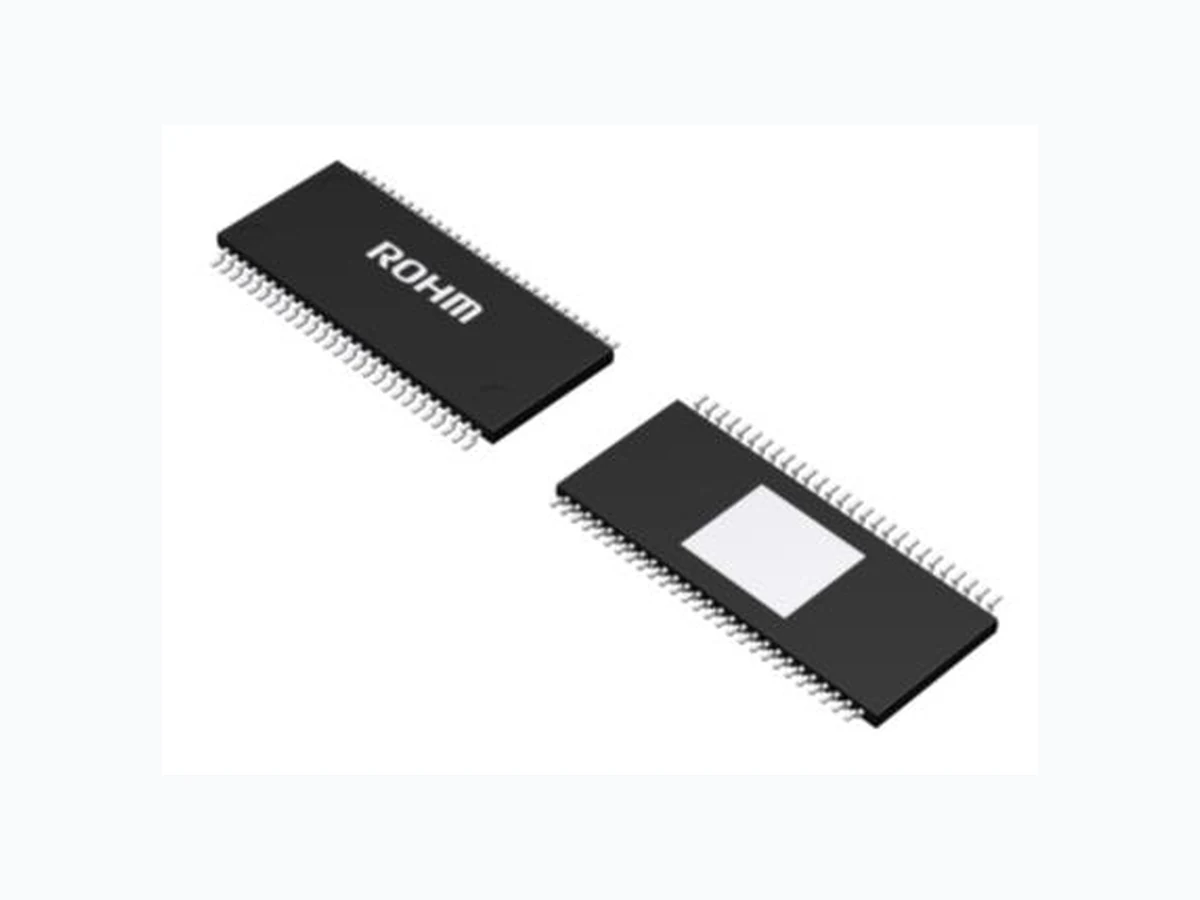
BD8256EFV-M_16 ROHM
Document overview
- Manufacturer or author: Provided By www.digicamel.com(FREE DATASHEET DOWNLOAD SITE)
- PDF pages: 53
Technical content
Features
Built-in Serial Peripheral Interface(SPI) High efficiency at 180° PWM for spindle driver Built-in 2-channel stepping motor driver for sled Built- in actuator over current protection circuit Built-in loading driver short-circuit protection AEC-Q100 Qualified
Applications
Car navigation Car AV Key Specifications Ron(Spindle): 1.0Ω(Typ) Ron(Loading): 1.5Ω(Typ) Power Supply Voltage Range: 4.5V to 10.5V Package W(Typ) × D(Typ) × H(Max) HTSSOP-B54 18.50mm × 9.50mm × 1.00mm Typical Application Circuit BD8256EFV-M M M FCTLO1+ FCTLO1- FCTLO2+ FCTLO2- LDO+ LDO- SLO1+ SLO1- SLO2+ SLO2- U_OUT V_OUT W_OUT PRTT SPCNF FG SLRNF1 SLRNF2 BHLD SPRNF HU+ HU- HV+ HV- HW+ HW- HALL_VC PREVCC VCC PREGND SLGND ACTGND HALL HALL HALL TKO+ TKO- FCTLRNF TKRNF FCTLCDET TKCDET PRTFT PRTLIM SAO1+ SAO1- SAO2+ SAO2- SHV SDI SDO SCLK SLV VREG PRTOUT SPGND MUTEB ERROUT PREVCC VCC VCC PREVCC SHVSHVSHV Figure 1. Typical Application Circuit
TSZ02201-0G1G0BK00030-1-2 © 2013 ROHM Co., Ltd. All rights reserved. Figure 2. Pin configuration Figure 3. Block diagram
7 HALL_VC Hall bias 34 PRTLIM Limit setting for actuator protect
8 SPCNF Spindle driver loop filter 35 MUTEB Mute input
9 BHLD Spindle current bottom hold 36 PRTOUT Protect output
10 SPRNF Spindle power supply and current sense 37 LDO- Loading driver negative output
11 FG FG output 38 LDO+ Loading driver positive output
12 W_OUT Spindle driver W output 39 ACTGND Actuator and loading power ground
13 V_OUT Spindle driver V output 40 TKO- Tracking driver negative output
14 U_OUT Spindle driver U output 41 TKO+ Tracking driver positive output
15 SPGND Spindle power ground 42 FCTLO2- Focus tilt driver 2 negative output
16 SLGND Sled power ground 43 FCTLO2+ Focus tilt driver 2 positive output
17 SLO1+ Sled driver 1 positive output 44 FCTLO1- Focus tilt driver 1 negative output
18 SLO1- Sled driver 1 negative output 45 FCTLO1+ Focus tilt driver 1 positive output
19 SLRNF1 Sled 1 power supply and current sense 46 SAO2- Sphere aberration 2 negative output
20 SLO2+ Sled driver 2 positive output 47 SAO2+ Sphere aberration 2 positive output
21 SLO2- Sled driver 2 negative output 48 SAO1- Sphere aberration 1 negative output
22 SLRNF2 Sled 2 power supply and current sense 49 SAO1+ Sphere aberration 1 positive output
23 ERROUT Serial data error output 50 TKCDET Current detect for tracking drive
24 SDO Serial data output 51 FCTLCDET Current detect for focus tilt drive
25 SDI Serial data input 52 FCTLRNF Focus tilt power supply and current sense
26 SCLK Serial clock input 53 TKRNF Tracking power supply and current sense
27 SLV Serial slave input 54 PREVCC Pre driver power supply
TSZ02201-0G1G0BK00030-1-2 © 2013 ROHM Co., Ltd. All rights reserved. 4.Apr.2016 Rev.004 www.rohm.com TSZ22111・15・001 BD8256EFV-M Absolute Maximum Ratings (Ta = 25°C) Parameter Symbol Rating Unit Pre Power supply voltage VVCC 15 V Power MOS power supply voltage VSPRNF,VSLRNF1,VSLRNF2 15 V PWM control / BTL power supply voltage VPREVCC,VTKRNF,VFCTLRNF 7 V Serial Output power supply VSHV 7 V Input pin voltage 1 VIN1 (1) 15 V Input pin voltage 2 VIN2 (2) 7 V Output pin voltage 1 VOUT1 (3) 15 V Output pin voltage 2 VOUT2 (4) 7 V Power Consumption Pd 2.0 (5) W Operating temperature range Topr -40 to +90 °C Storage temperature range Tstg -55 to +150 °C Junction temperature Tjmax 150 °C (1) BHLD, SPCNF (2) HU+, HU-, HV+, HV-, HW+, HW-, HALL_VC, PRTFT, PRTT, SLV, SCLK, SDI, TKCDET, FCTLCDET, MUTEB (3) FG, U_OUT, V_OUT, W_OUT, SLO1+, SLO1-, SLO2+, SLO2-, ERROUT, PRTLIM, PRTOUT, LDO+, LDO- (4) SDO, VREG, FCTLO1+, FCTLO1-, FCTLO2+, FCTLO2-, TKO+, TKO-, SAO1+, SAO1-, SAO2+, SAO2- (5) Ta=25°C, PCB (70mm×70mm×1.6mm, glass epoxy standard board) mounting. Derated by 16mW/°C when operating above 25°C Caution: Operating the IC over the absolute maximum ratings may damage the IC. In addition, it is impossible to predict all destructive situations such as short-circuit modes, open circuit modes, etc. Therefore, it is important to consider circuit protection measures, like adding a fus e, in case the IC is operated in a special mode exceeding the absolute maximum ratings. Recommended Operating Ratings (Ta = -40°C to +90°C) Parameter Symbol Limits Unit Min. Typ Max. Pre /Loading driver power supply voltage (6) VVCC 4.5 8 10.5 V Spindle driver power supply voltage (6)(7) VSPRNF - VVCC - V Sled motor driver power supply voltage (6)(7) VSLRNF1, VSLRNF2 - VVCC - V PWM control power supply voltage (6) VPREVCC 4.5 5 5.5 V Actuator driver power supply voltage (6) VFCTLRNF, VTKRNF 4.5 5 VPREVCC V Serial output power supply (6) VSHV 3.0 3.3 3.6 V (6) Consider power consumption when deciding power supply voltage . (7) Set the voltage same as VVCC.
TSZ02201-0G1G0BK00030-1-2 © 2013 ROHM Co., Ltd. All rights reserved. 4.Apr.2016 Rev.004 www.rohm.com TSZ22111・15・001 BD8256EFV-M VPREVCC =VTKRNF =VFCTLRNF =5V, VSHV =3.3V, RSPRNF=0.33Ω, RSLRNF=0.56Ω) Parameter Symbol Limits Unit Conditions Min. Typ Max. Circuit Current PREVCC Quiescent Current IQ1 - 18 30 mA MUTEB=High SPI=72h FE, 70h FE VCC Quiescent Current IQ2 - 7 14 mA PREVCC Standby Current IST1 - 3 6 mA MUTEB=Low VCC Standby Current IST2 - 1 2 mA Spindle Driver Hall Bias Voltage VHB 0.45 0.9 1.35 V IHB=10mA Input Bias Current IHIB - 0.5 3 μA Input Level VHIM 50 - - mVpp Common Mode Input Range VHICM 1.5 - 3.8 V Input Dead Zone (One Side) VDZSP 0 10 40 mV Input-Output Gain gmSP 0.98 1.24 1.50 A/V RSPRNF=0.33Ω, RL=2Ω Output ON Resistance (Total Sum) RONSP - 1 1.8 Ω IL=500mA Output limit Current ILIMSP 0.85 1.06 1.27 A RSPRNF=0.33Ω PWM Frequency fOSC - 100 - kHz RL=2Ω FG Output Low Level Voltage VFGL - 0.1 0.3 V 33KΩ pull-up(3.3V) Sled Motor Driver Input Dead Zone (One Side) VDZSL 5 15 30 mV Input-Output Gain gmSL 0.84 1.10 1.36 A/V RSLRNF1,2=0.56Ω, RL=8Ω Output ON Resistance (Total sum) RONSL - 2.2 3.3 Ω IL=500mA Output Limit Current ILIMSL 0.79 0.93 1.07 A RSLRNF1,2=0.56Ω PWM Frequency fOSC - 100 - kHz RL=8Ω Actuator Driver Output Offset Voltage VOFACT -50 0 50 mV Low Gain mode, RL=8Ω Output ON Resistance RONACT - 1.5 2.0 Ω IL=500mA Voltage Gain 1 GVACT1 10.5 11.7 12.9 dB Low Gain mode, RL=8Ω Voltage Gain 2 GVACT2 16.4 17.7 18.9 dB High Gain mode, RL=8Ω Loading Driver Output Offset Voltage VOFLD -100 0 100 mV Low Gain mode, RL=8Ω Output ON Resistance RONLD - 1.5 2.5 Ω IL=500mA Voltage Gain 1 GVLD1 15.2 17.2 19.2 dB Low Gain mode, RL=8Ω Voltage Gain 2 GVLD2 16.7 18.7 20.7 dB High Gain mode, RL=8Ω Actuator Protection Circuit PRTT/PRTF Default Voltage VPRTREF 1.00 1.06 1.12 V PRTT/PRTF Protect Detection Voltage VPRTDET 2.77 2.95 3.13 V PRTLIM Voltage VPRTLIM 500 530 560 mV Detection Input Offset Voltage VOFDET -5 0 5 mV Protect Sign Output PRTOUT Low Level Output Voltage VOL1 - 0.1 0.3 V 33kΩ pull-up(3.3V) ERROUT Low Level Output Voltage VOL2 - 0.1 0.3 V 33kΩ pull-up(3.3V) Logic Inputs (SDI,SCLK,SLV,MUTEB) Low Level Input Voltage VINL - - 0.5 V High Level Voltage VINH 2.2 - - V High Level Current (SDI,SCLK,MUTEB) IINH - 33 66 μA SDI,SCLK,MUTEB=3.3V Low Level Current (SLV) IINL -60 -30 - μA SLV=0V Function VCC Drop Mute Voltage VMVCC 3.4 3.8 4.2 V LVDS Output Difference Movement Output Voltage VOD 250 - 950 mV RL=100Ω Offset Voltage VOC 0.95 1.25 1.55 V RL=100Ω TSD TSD Junction Temperature(1) TTSD 150 175 200 °C TSD Hysteresis Temperature(1) THYS - 25 - °C (1) These items are specified by design,not tested during production
TSZ02201-0G1G0BK00030-1-2 © 2013 ROHM Co., Ltd. All rights reserved. 4.Apr.2016 Rev.004 www.rohm.com TSZ22111・15・001 BD8256EFV-M VPREVCC =VTKRNF =VFCTLRNF =5V, VSHV =3.3V, RSPRNF=0.33Ω, RSLRNF=0.56Ω) Parameter Symbol Limits Unit Conditions Min. Typ Max. Circuit Current PREVCC Quiescent Current IQ1 - 18 36 mA MUTEB=High SPI=72h FE, 70h FE VCC Quiescent Current IQ2 - 7 14 mA PREVCC Standby Current IST1 - 3 6 mA MUTEB=Low VCC Standby Current IST2 - 1 2 mA Spindle Driver Hall Bias Voltage VHB 0.45 0.9 1.35 V IHB=10mA Input Bias Current IHIB - 0.5 3 μA Input Level VHIM 50 - - mVpp Common Mode Input Range VHICM 1.5 - 3.8 V Input Dead Zone (One Side) VDZSP 0 10 45 mV Input-Output Gain gmSP 0.85 1.24 1.63 A/V RSPRNF=0.33Ω, RL=2Ω Output ON Resistance (Total Sum) RONSP - 1 1.8 Ω IL=500mA Output limit Current ILIMSP 0.85 1.06 1.27 A RSPRNF=0.33Ω PWM Frequency fOSC - 100 - kHz RL=2Ω FG Output Low Level Voltage VFGL - 0.1 0.3 V 33KΩ pull-up(3.3V) Sled Motor Driver Input Dead Zone (One Side) VDZSL 3 15 35 mV Input-Output Gain gmSL 0.84 1.10 1.36 A/V RSLRNF1,2=0.56Ω, RL=8Ω Output ON Resistance (Total sum) RONSL - 2.2 3.3 Ω IL=500mA Output Limit Current ILIMSL 0.79 0.93 1.07 A RSLRNF1,2=0.56Ω PWM Frequency fOSC - 100 - kHz RL=8Ω Actuator Driver Output Offset Voltage VOFACT -50 0 50 mV Low Gain mode, RL=8Ω Output ON Resistance RONACT - 1.5 2.0 Ω IL=500mA Voltage Gain 1 GVACT1 9.4 11.7 13.5 dB Low Gain mode, RL=8Ω Voltage Gain 2 GVACT2 15.4 17.7 19.5 dB High Gain mode, RL=8Ω Loading Driver Output Offset Voltage VOFLD -110 0 110 mV Low Gain mode, RL=8Ω Output ON Resistance RONLD - 1.5 2.5 Ω IL=500mA Voltage Gain 1 GVLD1 14.1 17.2 19.5 dB Low Gain mode, RL=8Ω Voltage Gain 2 GVLD2 15.6 18.7 21.0 dB High Gain mode, RL=8Ω Actuator Protection Circuit PRTT/PRTF Default Voltage VPRTREF 0.98 1.06 1.14 V PRTT/PRTF Protect Detection Voltage VPRTDET 2.65 2.95 3.25 V PRTLIM Voltage VPRTLIM 490 530 570 mV Detection Input Offset Voltage VOFDET -7 0 7 mV Protect Sign Output PRTOUT Low Level Output Voltage VOL1 - 0.1 0.3 V 33kΩ pull-up(3.3V) ERROUT Low Level Output Voltage VOL2 - 0.1 0.3 V 33kΩ pull-up(3.3V) Logic Inputs (SDI,SCLK,SLV,MUTEB) Low Level Input Voltage VINL - - 0.5 V High Level Voltage VINH 2.2 - - V High Level Current (SDI,SCLK,MUTEB) IINH - 33 75 μA SDI,SCLK,MUTEB=3.3V Low Level Current (SLV) IINL -75 -30 - μA SLV=0V Function VCC Drop Mute Voltage VMVCC 3.4 3.8 4.2 V LVDS Output Difference Movement Output Voltage VOD 250 - 950 mV RL=100Ω Offset Voltage VOC 0.95 1.25 1.55 V RL=100Ω
TSZ02201-0G1G0BK00030-1-2 © 2013 ROHM Co., Ltd. All rights reserved. 4.Apr.2016 Rev.004 www.rohm.com TSZ22111・15・001 BD8256EFV-M Typical Performance Curves -50 -25 0 25 50 75 100 Gain : GVACT1 (dB) Temparature (ºC) -50 -25 0 25 50 75 100 Gain : GVACT2 (dB) Temparature (ºC) FCTL1 Voltage gain 1 (Low gain mode) FCTL1 Voltage gain 2 (High gain mode) -50 -25 0 25 50 75 100 Gain : GVACT1 (dB) Temparature (ºC) -50 -25 0 25 50 75 100 Gain : GVACT2 (dB) Temparature (ºC) FCTL2 Voltage gain 1 (Low gain mode) FCTL2 Voltage gain 2 (High gain mode) PREVCC=5V GAIN_SELFCTL=0 DIFF_FCTL=1 PREVCC=5V GAIN_SELFCTL=1 DIFF_FCTL=1 PREVCC=5V GAIN_SELFCTL=0 DIFF_FCTL=1 PREVCC=5V GAIN_SELFCTL=1 DIFF_FCTL=1
TSZ02201-0G1G0BK00030-1-2 © 2013 ROHM Co., Ltd. All rights reserved. 4.Apr.2016 Rev.004 www.rohm.com TSZ22111・15・001 BD8256EFV-M Typical Performance Curves - continued -50 -25 0 25 50 75 100 Gain : GVACT1 (dB) Temparature (ºC) -50 -25 0 25 50 75 100 Gain : GVACT2 (dB) Temparature (ºC) TK Voltage gain 1 (Low gain mode) TK Voltage gain 2 (High gain mode) -50 -25 0 25 50 75 100 Gain : GVLD1 (dB) Temparature (ºC) -50 -25 0 25 50 75 100 Gain : GVLD2 (dB) Temparature (ºC) LD Voltage gain 1 (Low gain mode) LD Voltage gain 2 (High gain mode) PREVCC=5V GAIN_SELTK=0 PREVCC=5V GAIN_SELTK=1 VCC=8V GAIN_SELLD=0 VCC=8V GAIN_SELLD=1
TSZ02201-0G1G0BK00030-1-2 © 2013 ROHM Co., Ltd. All rights reserved. 4.Apr.2016 Rev.004 www.rohm.com TSZ22111・15・001 BD8256EFV-M 3. Details of Control Registers Functions of each register are as shown below. ・ REG 70h OUTPUT_EN1 (Read / Write) Each driver output settings (Hi-Z/Active) can be changed in REG 70h. Bit Name Default Function Set "0" Set "1" Reset
7 FCTL1_OUTEN 0 FCTL1 Output Enable Disable Enable A
6 FCTL2_OUTEN 0 FCTL2 Output Enable Disable Enable A
5 TK_OUTEN 0 TK Output Enable Disable Enable A
4 SL_OUTEN 0 SL1,SL2 Output Enable Disable Enable A
3 SA_OUTEN 0 SA1,SA2 Output Enable Disable Enable A
2 SP_OUTEN 0 SP Output Enable Disable Enable A
1 LD_OUTEN 0 LD Output Enable Disable Enable A
0 N/A 0 - - - -
・ REG 71h - Bit Name Default Function Set "0" Set "1" Reset 7 - - - - - - 6 - - - - - - 5 - - - - - - 4 - - - - - - 3 - - - - - - 2 - - - - - - 1 - - - - - - 0 - - - - - - ・ REG 72h POWER_SAVE1 (Read / Write) Power save mode settings for each block can be set in REG 72h. Power save mode makes the output Hi-Z and turns OFF the internal circuit to reduce the current consumption. Bit Name Default Function Set "0" Set "1" Reset
7 FCTL1_PSB 0 FCTL1 Block Power Save Enable Disable A
6 FCTL2_PSB 0 FCTL2 Block Power Save Enable Disable A
5 TK_PSB 0 TK Block Power Save Enable Disable A
4 SL_PSB 0 SL1,SL2 Block Power Save Enable Disable A
3 SA_PSB 0 SA1,SA2 Block Power Save Enable Disable A
2 SP_PSB 0 SP Block Power Save Enable Disable A
1 LD_PSB 0 LD Block Power Save Enable Disable A
TSZ02201-0G1G0BK00030-1-2 © 2013 ROHM Co., Ltd. All rights reserved. 4.Apr.2016 Rev.004 www.rohm.com TSZ22111・15・001 BD8256EFV-M ・ REG 73h - Bit Name Default Function Set "0" Set "1" Reset 7 - - - - - - 6 - - - - - - 5 - - - - - - 4 - - - - - - 3 - - - - - - 2 - - - - - - 1 - - - - - - 0 - - - - - - ・ REG 74h D RIVER_SET (Read / Write) Operation mode settings of the driver can be changed in REG 74h. Bit Name Default Function Set "0" Set "1" Reset
7 N/A 0 - - - -
6 SP_BRAKE 0 SP Brake Mode Short Brake Reverse Brake A
5 GAIN_SELFCTL 0 Gain Select FCTL Low Gain High Gain A
4 GAIN_SELTK 0 Gain Select TK Low Gain High Gain A
3 DIFF_FCTL 0 Differential FCTL Control Mode Differential Control Independent Control A
2 LD_BRAKE 0 LD Brake Mode LD Output Active LD Output
1 GAIN_SELLD 0 Gain Select LD Low Gain High Gain A
<Bit 6> Short brake/reverse brake can be selected as spindle brake mode. <Bit 5> Low/high gain mode of the focus/tilt driver's gain can be selected. <Bit 4> Low/high gain mode of the tracking driver's gain can be selected. <Bit 3> Differential/independent drive of the focus and tilt driver can be selected. See page 18 for more information. <Bit 2> Short brake mode (both positive & negative output low) can be activated when loading output is "Active". <Bit 1> Low/high gain mode of the loading driver's gain can be switched. ・ REG 75h RESET (Write) Resister settings and latched error flag can be reset in REG 75h. Bit Name Default Function Set "0" Set "1" Reset
7 RST_DAC 0 DAC Reset Normal Reset E
6 RST_CTLREG 0 Control Register Reset Normal Reset E
5 RST_PKTERR 0 Packet Bit Counts Error Reset Normal Reset E
4 RST_PKTSTOP 0 No Packet Input Error Reset Normal Reset E
3 RST_OCP 0 Actuator Overcurrent Protection Latch Off Reset Normal Reset E
2 RST_SHORT 0 LD Supply/Ground-Fault Protection Latch Off Reset Normal Reset E
1 N/A 0 - - - -
<Bit 7>Reset all DAC register value to 0. <Bit 6>Reset all control register value to default. <Bit 5>Reset packet bit counts error flag register value to 0. <Bit 4>Reset no packet input error flag register value to 0. <Bit 3>Reset actuator overcurrent protection flag register value to 0. <Bit 2>Reset loading supply/ground-fault protection flag register value to 0.
TSZ02201-0G1G0BK00030-1-2 © 2013 ROHM Co., Ltd. All rights reserved. 4.Apr.2016 Rev.004 www.rohm.com TSZ22111・15・001 BD8256EFV-M ・ REG 76h PKT_TIME (Read / Write) In REG 76h, you can specify or disable wait time until error operation in case of no SPI input. Bit Name Default Function Set "0" Set "1" Reset
6 N/A 0 - - - -
5 PKTSTOP_TIME1 0 SPI Packet Watchdog Timer
(00)=Disabled, (01)=1ms, A
4 PKTSTOP_TIME0 0 A
3 N/A 0 - - - -
2 N/A 0 - - - -
・ REG 77h STATUS_FLAG (Read) REG 77h outputs each protection state flag Bit Name Default Function Set "0" Set "1" Reset
7 ALL_ERR 0 All Error Flags Normal Abnormal *
6 OCP_FCTL 0 FCTL Overcurrent Detection Flag
(FCTL1, 2, TK Output Hi-Z) Normal Abnormal C
5 OCP_TK 0 TK Overcurrent Detection Flag
(FCTL1, 2, TK Output Hi-Z) Normal Abnormal C
4 SHORT_LD 0 LD Supply/Ground-Fault Protection
Detection Flag (LD Output Hi-Z) Normal Abnormal C
3 TSD 0 TSD Detection Flag (All Output Hi-Z) Normal Abnormal F
2 PKT_ERR 0 Number of Packet Bits Error Flag
(Flag Only) Normal Abnormal C
1 PKT_STOP 0 Packet Watchdog Timer (All Output Hi-Z) Normal Abnormal C
0 UVLO_VCC 0 VCC Low Voltage Fault Flag (All Output Hi-Z) Normal Abnormal D
<Bit7> *How to reset: ALL_ERR outputs all the error flags (OCP_FCTL, OCP_TK, SHORT_LD, TSD, PKT_ERR, PKT_STOP , UVLO_VCC). Therefore, reset conditions are depending on each flags. ・ REG 78h TEST0 (Read / Write) Bit Name Default Function Set "0" Set "1" Reset
7 Reserved 0 - - - D
6 Reserved 0 - - - D
5 Reserved 0 - - - D
4 Reserved 0 - - - D
3 Reserved 0 - - - D
2 Reserved 0 - - - D
1 Reserved 0 - - - D
0 Reserved 0 - - - D
TSZ02201-0G1G0BK00030-1-2 © 2013 ROHM Co., Ltd. All rights reserved. 4.Apr.2016 Rev.004 www.rohm.com TSZ22111・15・001 BD8256EFV-M ・ REG 79h TEST1 (Read / Write) Bit Name Default Function Set "0" Set "1" Reset
7 Reserved 0 - - - F
6 Reserved 0 - - - F
5 Reserved 0 - - - F
4 Reserved 0 - - - F
3 Reserved 0 - - - F
・ REG 7Ah TEST2 (Read / Write) Bit Name Default Function Set "0" Set "1" Reset
4 N/A 0 - - - -
2 Reserved 0 - - - F
1 Reserved 0 - - - F
・ REG 7Bh RST_CHECK (Rea d / Write) REG 7Bh is the flag confirming reset completion of registers listed in page 15. Bit Name Default Function Set "0" Set "1" Reset
7 RST_CHECKA 0 Reset A Completion Check Flag 0 1 A
6 RST_CHECKB 0 Reset B Completion Check Flag 0 1 B
5 N/A 0 - - - -
TSZ02201-0G1G0BK00030-1-2 © 2013 ROHM Co., Ltd. All rights reserved. 4.Apr.2016 Rev.004 www.rohm.com TSZ22111・15・001 BD8256EFV-M ◆ Register Reset Operations Type "A" : MODE Setting Bit (REG 70h, 72h, 74h, 76h, 7Bh[7]) Reset Conditions: VCC < 3.8V or PREVCC < 3.8V or VREG < 2.0V or MUTEB < 0.5V or RST_CTLREG(75h[6]) = 1 Type "B" : DAC Setting Bit (REG 01h~09h, 7Bh[6]) Reset Conditions: VCC < 3.8V or PREVCC < 3.8V or VREG < 2.0V or MUTEB < 0.5V or RST_DAC(75h[7]) = 1 Type "C" :Operational State (Latched) Output Bit (REG 77h[1,2,4,5,6]) Reset Conditions: VCC < 3.8V or PREVCC < 3.8V or VREG < 2.0V or MUTEB < 0.5V or RST_CTLREG (75h[6]) = 1 or RST_PKTERR (75h[5]) = 1 (for PKT_ERR(77h[2])) or RST_PKTSTOP (75h[4]) = 1 (for PKT_STOP(77h[1])) or RST_OCP (75h[3]) = 1 (for OCPFCTL(77h[6]) and OCPTK(77h[5])) or RST_SHORT (75h[2]) = 1 (for SHORT_LD(77h[4])) Type "D" :Operational State (Continuously Updated) Output Bit 1 (REG 77h[0]) Reset Conditions: PREVCC < 2.0V or VREG < 1.2V or MUTEB < 0.5V Type "E" :Reset Setting Bit (REG 75h) Reset Conditions: Self-reset (If set to 1, automatically returns to "0" following reset operation) Type "F" :Operational State (Continuously Updated) Output Bit 2 (REG 77h[3]) Reset Conditions: VCC < 3.8V or PREVCC < 3.8V or VREG < 2.0V or MUTEB < 0.5V Reset Operations DAC REG D7 D6 D5 D4 D3 D2 D1 D0 D7 D6 RST_SHORT 75h[2] = 1 *1 ○ RST_OCP 75h[3] = 1 *1 ○ ○ RST_PKTSTOP 75h[4] = 1 *1 ○ RST_PKTERR 75h[5] = 1 *1 ○ RST_DAC 75h[7] = 1 ○ *1 ○ MUTEB < 0.5V Reset condition Control REG 01h ~ 09h 70h 72h 74h Soft Self reset 75h 76h 77h 7Bh Hard VCC < 3.8V PREVCC < 2.0V PREVCC < 3.8V *1 Reset conditions of REG 77h[7] are dependent upon REG 77h[6]-77h[0].
TSZ02201-0G1G0BK00030-1-2 © 2013 ROHM Co., Ltd. All rights reserved. as high level voltage in 3-state CMOS output. Figure 9. SPI Input / Output Terminal Processing
TSZ02201-0G1G0BK00030-1-2 © 2013 ROHM Co., Ltd. All rights reserved. Suppose that voltage difference between positive/negative outputs is VOUT, VOUT can be expressed as follows. Here, GVACT value will be different as below depending upon gain mode settings. VDAC, the DAC output voltage, can be obtained from DAC register settings through the following equation.
- In low gain mode setting. Output voltage saturation is not taken into account in the table.
Figure 10. DAC Setting vs. VDAC/VOUT (in low gain mode)
TSZ02201-0G1G0BK00030-1-2 © 2013 ROHM Co., Ltd. All rights reserved. 4.Apr.2016 Rev.004 www.rohm.com TSZ22111・15・001 BD8256EFV-M DFCTL2=100h, DFCTL1=080hの場合 DFCTL2+DFCTL1 : 180h DFCTL2-DFCTL1 : 080h DFCTL2=100h, DFCTL1=F80hの場合 DFCTL2+DFCTL1 : 080h DFCTL2-DFCTL1 : 180h ◆ FCTL 1, FCTL 2 Differential Drive Mode If you set REG 74h[3] DIFF_FCTL to 0, FCTL1 and FCTL2 turn into differential drive mode. In this mode, 12 bit data to be input into DAC of FCTL1 and FCTL2 will be the values obtained by the following equations. DAC FCTL1, 2 shows 12-bit data to be input into respective DACs. Note that the DAC output voltage V DAC, gain GV ACT and output voltage V OUT are to be in accordance with page 17. DACFCTL1 = DFCTL2 + DFCTL1 DACFCTL2 = DFCTL2 – DFCTL1 Operation images during the differential drive mode are as shown below. FCTL1, 2 Differential Operation Images when DIFF_FCTL=0 DFCTL1 = 0x000 FCTL1 FCTL2 DFCTL1 > 0x000 FCTL1 FCTL2 DFCTL1 < 0x000 FCTL2 FCTL1 A B A : +FCTL1 B : -FCTL1 VOUT DFCTL2 Code 7FFh800h 7FFh800h 7FFh800h
0 VOUTVOUT
B A A : +FCTL1 B : -FCTL1 DFCTL2 Code DFCTL2 Code If DFCTL2=100h and DFCTL1=080h If DFCTL2=100h and DFCTL1=F80h
TSZ02201-0G1G0BK00030-1-2 © 2013 ROHM Co., Ltd. All rights reserved. Suppose that voltage difference between positive/negative outputs is VOUT, VOUT can be expressed as follows. Here, GVLD value will be different as below depending upon gain mode settings. VDAC, the DAC output voltage, can be obtained from DAC register settings through the following equation.
- In low gain mode setting. Output voltage saturation is not taken into account in the table.
Figure 11. DAC Setting vs. VDAC/VOUT (in low gain mode)
TSZ02201-0G1G0BK00030-1-2 © 2013 ROHM Co., Ltd. All rights reserved. Suppose that IO PEAK represents peak output current, IO PEAK can be expressed in the following ways. and they can be obtained respectively as follows. VDAC, the DAC output voltage, can be obtained from DAC register settings through the following equation.
1.10 A/V
Figure 12. IO PEAK Characteristics (When set as RSLRNF=0.56 Ω).
TSZ02201-0G1G0BK00030-1-2 © 2013 ROHM Co., Ltd. All rights reserved. Suppose that IO PEAK represents peak output current, IO PEAK can be expressed in the following ways. and they can be obtained respectively as follows. VDAC, the DAC output voltage, can be obtained from DAC register settings through the following equation.
1.24 A/V
Figure 13. IO PEAK Characteristics (When set as RSPRNF=0.33 Ω).
TSZ02201-0G1G0BK00030-1-2 © 2013 ROHM Co., Ltd. All rights reserved. SAO1+ and SAO1- correspond to DSA1, while SAO2+ and SAO2- to DSA2, and they can be controlled independently. Recommended operation frequency of each output is 10 kHz or less. Figure 14. Timing Chart of LVDS for Spherical Aberration Driver
TSZ02201-0G1G0BK00030-1-2 © 2013 ROHM Co., Ltd. All rights reserved.
- Hall input (Pin 1 to Pin 6) / Hall bias (Pin 7) (Spindle)
Hall elements can be connected either in series or in parallel as shown in Figure 24. Hall input voltage should be set within the range of 1.5 V to 3.8 V (In-phase input voltage range of hall amplifier: VHICM). to connect resistor parallel to a resistor. (Pin 30) and the hall bias (Pin 7) to open. For connection details, please refer to the page with Application Example. Figure 24. Example of Hall Elements Connection than that, High logic of FG output can be reversed to become "Low" as soon as spindle output becomes Hi-Z. recommended to insert a capacitor (around 0.01 µF) between positive and negative sides of the hall signal. speed of motor rotation to ensure sufficient output current when using the reverse brake. from the IC due to the effect of line impedances. Therefore, this capacitor should be placed near the IC.
TSZ02201-0G1G0BK00030-1-2 © 2013 ROHM Co., Ltd. All rights reserved. 4.Apr.2016 Rev.004 www.rohm.com TSZ22111・15・001 BD8256EFV-M 9. Spindle Dricer Input-Output Timing Chart HU- HU+ HV- HV+ HW+ HW- U_OUT V_OUT W_OUT Sink Source Sink Source Sink Source FG Low High HU- HU+ HV- HV+ HW+ HW- U_OUT V_OUT W_OUT Sink Source Sink Source Sink Source FG Low High (a) Forward Mode (DSP>000h) (b) Short Brake Mode (DSP<000h, REG 74h[6]=0) (c) Reverse Brake Mode (DSP<000h, REG 74h[6]=1) (b) Anti-reverse Mode (DSP<000h, REG 74h[6]=1, after reverse detected) A B C D E FState G H I J K LState
TSZ02201-0G1G0BK00030-1-2 © 2013 ROHM Co., Ltd. All rights reserved. 4.Apr.2016 Rev.004 www.rohm.com TSZ22111・15・001 BD8256EFV-M Start-up Operation 1. Startup Signals ・5V Power supply : PREVCC, FCTLRNF, TKRNF ・8V Power supply : VCC, SPRNF, SLRNF1, SLRNF2 ・3.3V Power supply : SHV ・MUTEB (Input terminal) : Standby (Low) / Active (High) setting for whole IC ・XXX_PSB (SPI control signal) : Power save (0) / Active (1) setting for control circuits of 9ch blocks ・XXX_EN (SPI control signal) : Open (0) / Active (1) setting for output of 9ch blocks ・MUTEB_D (Internal signal) : Standby / active control for analog block There may be 15 µs (Max) delay from MUTEB. ・RESETB (Internal signal) : Reset /active control for SPI block and logic block 2. Start-up and Shut-down Sequences Make sure to turn on 5V power supply before 8V and 3.3 V power supplys. Otherwise internal logic becomes indefinite and abnormal output may be produced. As long as 5V power is turned on first, either 8V or 3.3V may be turned on next. There are no special requirements on sequence of power shut down. MUTEB XXX_PSB XXX_EN Input Signal MUTEB_D Protect Circuit Active RESETB Internal Signal (Reference) Start to Receive SPI Input MUTEB_DELAY 15μs (Max) OUTPUT RESET_DELAY 30μs (Max) Analog Block Active Logic Block Active Output State OUTEN_DELAY 45μs (Max) 0 1 High Low 0 1 OPEN Active Power Supply 4.0V Turn on 8V and 3.3V power supply after 5V becomes 4.0V or greater. 4.0V Input High on MUTEB after 8V becomes 4.0V or greater. 3.3V
TSZ02201-0G1G0BK00030-1-2 © 2013 ROHM Co., Ltd. All rights reserved.
- Output Voltage State (Spindle / Sled Motor)
- PWM Oscillation Frequency (Spindle / Sled Motor)
PWM oscillation of the spindle and the sled motor is internally free-running. Oscillation frequency is 100 kHz (Typ). less, output of all channels turns OFF (Hi-Z). operational voltage range and some register state may be unsustainable depending on degree of voltage drop. Thermal shutdown (over temperature protection circuit) is built-in in order to prevent thermal breakage of IC. outputs are turned OFF (Hi-Z). and all register states may be unsustainable depending on degree of temperature rise.
- Loading Supply/Ground-Fault Protection
output POWER MOS if loading output is supply/ground-faulted. output is OFF-latched. Note that 1 Vf = 0.7V (Typ). dependent on the output voltage. See Figure 25.
- REG 77h[4] SHORT_LD is set to "1" if the loading supply/ground-fault protection is activated.
protection may be activated against the noise of 10 μs (Typ) or greater. Figure 25. Output voltage vs Ground short detection current
TSZ02201-0G1G0BK00030-1-2 © 2013 ROHM Co., Ltd. All rights reserved. 4.Apr.2016 Rev.004 www.rohm.com TSZ22111・15・001 BD8256EFV-M 6. Packet Bit Counts Error Serial input signal of this IC consists of 16 bits in one packet. If counts of the SCLK rising during the period between falling and rising of SLV are anything but 16 times, it is determined as a erroneous packet and REG 7 7h[2] PKT_ERR is set to "1". Any data determined as an erroneous packet are nullified, and the registers maintain the state immediately before the error. Note that PKT_ERR remains at "1" even though the next 1 packet is sent and counts of the clock rising during the period between falling and rising of SLV are 16 times. But this error will not open (i.e. turn off) the output circuit. 7. Packet Watchdog Timer If REG 76h[5,4] PKTSTOP_TIME is preset to anything but "00" and there is no valid packet (16 bits) rising of SLV within this preset time period, REG 77h[1] PKT_STOP will be set to "1" and all outputs will be OFF-latched (Hi-Z). * You can reset the protection mode by resetting REG 75h[4] RST_PKTSTOP if the protection mode is activated and the output is OFF-latched. 8. ERROUT Terminal If either the packet bit counts error or the packet watchdog timer is activated, this terminal switches to High as an error flag. 9. PRTOUT Terminal Operational stat e of MUTEB, UVLO and actuator overcurrrent protection is output to PRTOUT terminal. Output conditions are as per the following table. MUTEB UVLO Overcurrent Protection PRTOUT L ON ON OFF OFF ON OFF H ON ON OFF OFF ON OFF L *When connected with pull-up resistor. 10. VREG Terminal VREG terminal is the regurator output for internal blocks. A 0.01μF compensating capacitor shall be connected across the VREG terminal. Any value less than 0.01μF, or no compensating capacitor will result in system instablity.
TSZ02201-0G1G0BK00030-1-2 © 2013 ROHM Co., Ltd. All rights reserved.
- Actuator Overcurrent Protection (OCP: Over Current Protection)
This is the function to protect the actuator when overcurrent condition is detected over a preset time period. 75h[3] RST_OCP is set to "1" at that timing. Figure 26. OCP Timing Chart
TSZ02201-0G1G0BK00030-1-2 © 2013 ROHM Co., Ltd. All rights reserved.
- Example of Constants Setting for Actuator Overcurrent Protection Circuit
Figure 27. Overcurrent Protection Circuit Constants Capacitor-recharging/discharging current ISINK and ISOURCE can be obtained respectively as follows. Typ) through discharge of C, can be obtained as follows.
- The above voltmeters indicate where electric characteristics should be measured.
( ) indicates processing in case of not using OCP function.
TSZ02201-0G1G0BK00030-1-2 © 2013 ROHM Co., Ltd. All rights reserved. close, shield the RF signal line with GND except the stable GND. line and the actuator drive output line. (3) Connect the motor system and the actuator system to separate flexible cables. Figure 32. RF Noise Suppression
TSZ02201-0G1G0BK00030-1-2 © 2013 ROHM Co., Ltd. All rights reserved. Power Supply and Ground *(○) is pin. Figure 33. Power Supply and Ground
TSZ02201-0G1G0BK00030-1-2 © 2013 ROHM Co., Ltd. All rights reserved. Figure 34. Application Example
TSZ02201-0G1G0BK00030-1-2 © 2013 ROHM Co., Ltd. All rights reserved. 4.Apr.2016 Rev.004 www.rohm.com TSZ22111・15・001 BD8256EFV-M ▼Recommended values1 for Application Example1 Component name Component value Product name Manufacturer CVCC 0.1μF GCM188R11H Series murata 47μF UCD1E470MCL Nichicon CPREVCC 0.1μF GCM188R11H Series murata CBHLD 470pF GCM188R11H Series murata CSPVM 0.1μF GCM188R11H Series murata 47μF UCD1E470MCL Nichicon RSPRNF 0.33Ω MCR100 Series Rohm CSPRNF 0.1μF GCM188R11H Series murata CSPCNF 0.01μF GCM188R11H Series murata CAVM 0.1μF GCM188R11H Series murata 47μF UCD1E470MCL Nichicon RTKRNF 0.5Ω MCR100 Series Rohm RTKCDET 10kΩ MCR03 Series Rohm RFCTLRNF 0.5Ω MCR100 Series Rohm RFCTLCDET 10kΩ MCR03 Series Rohm CPRTT 0.1μF GCM188R11H Series murata CPRTFT 0.1μF GCM188R11H Series murata CSLVM 0.1μF GCM188R11H Series murata 47μF UCD1E470MCL Nichicon RSLRNF1 0.56Ω MCR100 Series Rohm RSLRNF2 0.56Ω MCR100 Series Rohm CSLRNF1 0.1μF GCM188R11H Series murata CSLRNF2 0.1μF GCM188R11H Series murata CSHV 0.1μF GCM188R11H Series murata RHVCC 100Ω MCR03 Series Rohm RHALLVC 100Ω MCR03 Series Rohm CVREG 0.01μF GCM188R11H Series murata RPRTLIM 47kΩ MCR03 Series Rohm RFG 3.3kΩ MCR03 Series Rohm RPRTOUT 33kΩ MCR03 Series Rohm RERROUT 33kΩ MCR03 Series Rohm
TSZ02201-0G1G0BK00030-1-2 © 2013 ROHM Co., Ltd. All rights reserved.
TSZ02201-0G1G0BK00030-1-2 © 2013 ROHM Co., Ltd. All rights reserved. 4.Apr.2016 Rev.004 www.rohm.com TSZ22111・15・001 BD8256EFV-M ▼Recommended values2 for Application Example2 Component name Component value Product name Manufacturer CVCC 0.1μF GCM188R11H Series murata 47μF UCD1E470MCL Nichicon CPREVCC 0.1μF GCM188R11H Series murata CBHLD 470pF GCM188R11H Series murata CSPVM 0.1μF GCM188R11H Series murata 47μF UCD1E470MCL Nichicon RSPRNF 0.33Ω MCR100 Series Rohm CSPRNF 0.1μF GCM188R11H Series murata CSPCNF 0.01μF GCM188R11H Series murata CAVM 0.1μF GCM188R11H Series murata 47μF UCD1E470MCL Nichicon RTKRNF 0.5Ω MCR100 Series Rohm RTKCDET 10kΩ MCR03 Series Rohm RFCTLRNF 0.5Ω MCR100 Series Rohm RFCTLCDET 10kΩ MCR03 Series Rohm CPRTT 0.1μF GCM188R11H Series murata CPRTFT 0.1μF GCM188R11H Series murata CSLVM 0.1μF GCM188R11H Series murata 47μF UCD1E470MCL Nichicon RSLRNF1 0.56Ω MCR100 Series Rohm RSLRNF2 0.56Ω MCR100 Series Rohm CSLRNF1 0.1μF GCM188R11H Series murata CSLRNF2 0.1μF GCM188R11H Series murata CSHV 0.1μF GCM188R11H Series murata RHVCC 10Ω(1) MCR03 Series Rohm RHALL 100Ω(1) MCR03 Series Rohm RHALLVC 100Ω(1) MCR03 Series Rohm CVREG 0.01μF GCM188R11H Series murata RPRTLIM 47kΩ MCR03 Series Rohm RFG 3.3kΩ MCR03 Series Rohm RPRTOUT 33kΩ MCR03 Series Rohm RERROUT 33kΩ MCR03 Series Rohm (1)at HVCC = 3.3V, Hall elements 25°C resistance = 250Ω~450Ω
TSZ02201-0G1G0BK00030-1-2 © 2013 ROHM Co., Ltd. All rights reserved. Figure 35. Power dissipation Note 1: Power dissipation calculated when mounted on 70mm X 70mm X 1.6mm glass epoxy substrate 1-layer platform. The board and the back exposure heat radiation board are connected through solder.
TSZ02201-0G1G0BK00030-1-2 © 2013 ROHM Co., Ltd. All rights reserved. 4.Apr.2016 Rev.004 www.rohm.com TSZ22111・15・001 BD8256EFV-M Input-Output Equivalent Circuit (Number is pin number, the value of resistor and capacitor is typical value) 54 54 30 30 50kΩ 4pF 50kΩ 12kΩ 10kΩ 100kΩ 8.SPCNF 9.BHLD 10kΩ 500Ω 500Ω 500Ω10kΩ 6kΩ 5kΩ 10kΩ 10kΩ 200kΩ 10.SPRNF 11.FG 2kΩ 5kΩ 1.03kΩ 12.W_OUT, 13.V_OUT, 14.U_OUT, 19 30kΩ 10pF 23.ERROUT, 36.PRTOUT 24.SDO 1kΩ23
TSZ02201-0G1G0BK00030-1-2 © 2013 ROHM Co., Ltd. All rights reserved. 4.Apr.2016 Rev.004 www.rohm.com TSZ22111・15・001 BD8256EFV-M 25.SDI, 26.SCLK, 35.MUTEB 27.SLV 25 1kΩ 100kΩ 10kΩ 100kΩ 1kΩ 100kΩ 28.VREG 31.PRTT, 32.PRTFT 100kΩ 3030 1kΩ 1kΩ 1kΩ 10kΩ 10kΩ 1kΩ 5352 34.PRTLIM 37.LDO-, 38.LDO+ 1kΩ1kΩ 40.TKO+, 41.TKO-, 30 30 4730kΩ 30kΩ 50.TKCDET, 51.FCTLCDET 52.FCTLRNF, 53.TKRNF 10kΩ 1kΩ 1kΩ 10kΩ
TSZ02201-0G1G0BK00030-1-2 © 2013 ROHM Co., Ltd. All rights reserved. 4.Apr.2016 Rev.004 www.rohm.com TSZ22111・15・001 BD8256EFV-M Operational Notes 1. Reverse Connection of Power Supply Connecting the power supply in reverse polarity can damage the IC. Take precautions against reverse polarity when connecting the power supply , such as mounting an external diode between the power supply and the IC ’s power supply terminals. 2. Power Supply Lines Design the PCB layout pattern to provide low impedance supply lines. Separate the ground and supply lines of the digital and analog blocks to prevent noise in the ground and supply lines of the digital block from affect ing the analog block. Furthermore, connect a capacitor to ground at all power supply pins . Consider the effect of temperature and aging on the capacitance value when using electrolytic capacitors. 3. Ground Voltage Ensure that no pins are at a voltage below that of the ground pin at any time, even during transient condition. However, pins that drive inductive loads (e.g. motor driver outputs, DC -DC converter outputs) may inevitably go below ground due to back EMF or electromotive force. In such cases, the use r should make sure that such voltages going below ground will not cause the IC and the system to malfunction by examining carefully all relevant factors and conditions such as motor characteristics, supply voltage, operating frequency and PCB wiring to name a few. 4. Ground Wiring Pattern When using both small-signal and large-current ground traces, the two ground traces should be routed separately but connected to a single ground at the reference point of the application board to avoid fluctuations in the sm all-signal ground caused by large currents. Also ensure that the ground traces of external components do not cause variations on the ground voltage. The ground lines must be as short and thick as possible to reduce line impedance. 5. Thermal Consideration Should by any chance the power dissipation rating be exceeded the rise in temperature of the chip may result in deterioration of the properties of the chip. The absolute maximum rating of the Pd stated in this specification is when the IC is mounted on a 70m m x 70mm x 1.6mm glass epoxy board. In case of exceeding this absolute maximum rating, increase the board size and copper area to prevent exceeding the Pd rating. 6. Recommended Operating Conditions These conditions represent a range within which the expected characteristics of the IC can be approximately obtained. The electrical characteristics are guaranteed under the conditions of each parameter. 7. Rush Current When power is first supplied to the IC, it is possible that the internal logic may be unstable an d inrush current may flow instantaneously due to the internal powering sequence and delays, especially if the IC has more than one power supply. Therefore, give special consideration to power coupling capacitance, power wiring, width of ground wiring, and routing of connections. 8. Operation Under Strong Electromagnetic Field Operating the IC in the presence of a strong electromagnetic field may cause the IC to malfunction. 9. Testing on Application Boards When testing the IC on an application board, connecting a capacitor directly to a low -impedance output pin may subject the IC to stress. Always discharge capacitors completely after each process or step. The IC’s power supply should always be turned off completely before connecting or removing it from the test setup during the inspection process. To prevent damage from static discharge, ground the IC during assembly and use similar precautions during transport and storage. 10. Inter-pin Short and Mounting Errors Ensure that the direction and position are correct w hen mounting the IC on the PCB. Incorrect mounting may result in damaging the IC. Avoid nearby pins being shorted to each other especially to ground , power supply and output pin . Inter-pin shorts could be due to many reasons such as metal particles, water droplets (in very humid environment) and unintentional solder bridge deposited in between pins during assembly to name a few.
TSZ02201-0G1G0BK00030-1-2 © 2013 ROHM Co., Ltd. All rights reserved. the IC. So unless otherwise specified, unused input terminals should be connected to the power supply or ground line.
- Regarding the Input Pin of the IC
When GND > Pin A and GND > Pin B, the P-N junction operates as a parasitic diode. When GND > Pin B, the P-N junction operates as a parasitic transistor. Figure 36. Example of monolithic IC structure temperature and the decrease in nominal capacitance due to DC bias and others.
- Area of Safe Operation (ASO)
- Thermal Shutdown Circuit(TSD)
the TSD threshold, the circuits are automatically restored to normal operation.
TSZ02201-0G1G0BK00030-1-2 © 2013 ROHM Co., Ltd. All rights reserved. 4.Apr.2016 Rev.004 www.rohm.com TSZ22111・15・001 BD8256EFV-M
Ordering Information
EFV : HTSSOP-B54 Packaging and forming specification M: High relaiability E2: Embossed tape and reel (HTSSOP-B54) Marking Diagram HTSSOP-B54 (TOP VIEW) B D 8 2 5 6 E F V Part Number Marking LOT Number 1PIN MARK
TSZ02201-0G1G0BK00030-1-2 © 2013 ROHM Co., Ltd. All rights reserved. 4.Apr.2016 Rev.004 www.rohm.com TSZ22111・15・001 BD8256EFV-M Physical Dimension, Tape and Reel Information Package Name HTSSOP-B54
TSZ02201-0G1G0BK00030-1-2 © 2013 ROHM Co., Ltd. All rights reserved. 4.Apr.2016 Rev.004 www.rohm.com TSZ22111・15・001 BD8256EFV-M
Revision History
1.Aug.2013 002 New release 25.Apr.2014 003 P .1 Add the sentence of AEC-Q100 Qualified at the features 4.Apr.2016 004 P.2 Change : Pin3 HV+ V negative⇒V positive Pin4 HV- V positive⇒V negative P .3 Change : (2)FCCDET⇒FCTLCDET, (3)LDO⇒LDO-, (4)SAO2⇒SAO2- P .4, 5 Add RL=8Ω at the conditions P.9 Change : **P9⇒P .15 P .18 Change : DACFCTL2 = DFCTL2 - DFCTL2⇒DACFCTL2 = DFCTL2 - DFCTL1 P .20 Add *Condition:RSLRNF=0.56Ω P .21 Add *Condition:RSPRNF=0.33Ω P .26 Change : Figure 22. CSPRNF⇒CSPCNF Add : Explanation about Hall bias P .33 Change : VPRTDET:3.0V(Typ)⇒2.95V(Typ), Vd=VPRTLIM-VPRREF⇒Vd=VPRTDET-VPRTREF P .37 Change : FCTLO+, SA1O+, SA2O- ⇒FCTLO1+, SAO1+, SAO2- P .38 Change : title : from Application Example to Application Example1, Change : FCRNF, FCCDET, RFCRNF, RFCCDET⇒FCTLRNF, FCTLCDET, RFCTLRNF, RFCTLCDET P .39 Change title : from Recommended values to Recommended values1 for Application Example1 Change : RFCRNF, RFCCDET⇒RFCTLRNF, RFCTLCDET P .40 New addition : Application Example2 P .41 New addition : Recommended values2 for Application Example2 Update : Figure about Pin10, 25, 26, 35, 27, 28, 34, 52, 53
Notice-PAA-E Rev.003 © 2015 ROHM Co., Ltd. All rights reserved. Notice Precaution on using ROHM Products 1. If you intend to use our Products in devices requiring extremely high reliability ( such as medical equipment (Note 1), aircraft/spacecraft, nuclear power controllers, etc.) and whose malfunction or failure may cause loss of human life , bodily injury or serious damage to property ( “Specific Applications ”), please consult with the ROHM sales representative in advance. Unless otherwise agreed in writing by ROHM in advance, ROHM shall not be in any way responsible or liable for any damages, expenses or losses incurred by you or third parties arising from the use of any ROHM’s Products for Specific Applications. (Note1) Medical Equipment Classification of the Specific Applications JAPAN USA EU CHINA CLASSⅢ CLASSⅢ CLASSⅡb CLASSⅢ CLASSⅣ CLASSⅢ 2. ROHM designs and manufactures its Products subject to strict quality control system. However, semiconductor products can fail or malfunction at a cert ain rate. Please be sure to implement, at your own responsibilities, adequate safety measures including but not limited to fail -safe design against the physical injury, damage to any property, which a failure or malfunction of our Products may cause. The following are examples of safety measures: [a] Installation of protection circuits or other protective devices to improve system safety [b] Installation of redundant circuits to reduce the impact of single or multiple circuit failure 3. Our Products are not designed under any special or extraordinary environments or conditions, as exemplified below . Accordingly, ROHM shall not be in any way responsible or liable for any damages, expenses or losses arising from the use of any ROHM’s Products under any special or extraordinary environments or conditions . If you intend to use our Products under any special or extraordinary environments or conditions (as exemplified below), your independent verification and confirmation of product performance, reliability, etc, prior to use, must be necessary: [a] Use of our Products in any types of liquid, including water, oils, chemicals, and organic solvents [b] Use of our Products outdoors or in places where the Products are exposed to direct sunlight or dust [c] Use of our Products in places where the Products are exposed to sea wind or corrosive gases, including Cl2, H2S, NH3, SO2, and NO2 [d] Use of our Products in places where the Products are exposed to static electricity or electromagnetic waves [e] Use of our Products in proximity to heat-producing components, plastic cords, or other flammable items [f] Sealing or coating our Products with resin or other coating materials [g] Use of our Products without cleaning residue of flux (even if you use no -clean type fluxes, cle aning residue of flux is recommended); or Washing our Products by using water or water -soluble cleaning agents for cleaning residue after soldering [h] Use of the Products in places subject to dew condensation 4. The Products are not subject to radiation-proof design. 5. Please verify and confirm characteristics of the final or mounted products in using the Products. 6. In particular, if a transient load (a large amount of load applied in a short period of time, such as pulse. is applied, confirmation of performance characteristics after on -board mounting is strongly recommended. Avoid applying power exceeding normal rated power; exceeding the power rating under steady -state loading condition may negatively affect product performance and reliability. 7. De-rate Power Dissipation d epending on ambient temperature. When used in sealed area, confirm that it is the use in the range that does not exceed the maximum junction temperature. 8. Confirm that operation temperature is within the specified range described in the product specification. 9. ROHM shall not be in any way responsible or liable for failure induced under de viant condition from what is defined in this document. Precaution for Mounting / Circuit board design 1. When a highly active halogenous (chlorine, bromine, etc.) flux is used, the residue of flux may negatively affect product performance and reliability. 2. In principle, the reflow soldering method must be used on a surface -mount products, the flow soldering method must be used on a through hole mount products. If the flow soldering method is preferred on a surface -mount products, please consult with the ROHM representative in advance. For details, please refer to ROHM Mounting specification
Notice-PAA-E Rev.003 © 2015 ROHM Co., Ltd. All rights reserved. Precautions Regarding Application Examples and External Circuits 1. If change is made to the constant of an external circuit, please allow a sufficient margin considering variations of the characteristics of the Products and external components, including transient characteristics, as well as static characteristics. 2. You agree that application notes, reference designs, and associated data and information contained in this document are presented only as guidance for Products use . Therefore, in case you use such information, you are solely responsible for it and you must exercise your own independent verification and judgment in the use of such information contained in this document. ROHM shall not be in any way responsible or liable for any damages, expenses or losses incurred by you or third parties arising from the use of such information. Precaution for Electrostatic This Product is electrostatic sensitive pr oduct, which may be damaged due to electrostatic discharge. Please take proper caution in your manufacturing process and stor age so that voltage exceeding the Products maximum rating will not be applied to Products. Please take special care under dry condi tion (e.g. Grounding of human body / equipment / solder iron, isolation from charged objects, setting of Ionizer, friction prevention and temperature / humidity control). Precaution for Storage / Transportation 1. Product performance and soldered connections may deteriorate if the Products are stored in the places where: [a] the Products are exposed to sea winds or corrosive gases, including Cl2, H2S, NH3, SO2, and NO2 [b] the temperature or humidity exceeds those recommended by ROHM [c] the Products are exposed to direct sunshine or condensation [d] the Products are exposed to high Electrostatic 2. Even under ROHM recommended storage condition, solderability of products out of recommended storage time period may be degraded. It is strongly recommended to confirm solderability before using Products of which storage time is exceeding the recommended storage time period. 3. Store / transport cartons in the correct direction, which is indicated on a carton with a symbol. Otherwise bent leads may occur due to excessive stress applied when dropping of a carton. 4. Use Products within the specified time after opening a humidity barrier bag. Baking is required before using Products of which storage time is exceeding the recommended storage time period. Precaution for Product Label A two-dimensional barcode printed on ROHM Products label is for ROHM’s internal use only. Precaution for Disposition When disposing Products please dispose them properly using an authorized industry waste company. Precaution for Foreign Exchange and Foreign Trade act Since concerned goods might be fallen under listed items of export control prescribed by Foreign exchange and Foreign trade act, please consult with ROHM in case of export. Precaution Regarding Intellectual Property Rights 1. All information and data including but not limited to application example contained in this document is for reference only. ROHM does not warrant that foregoing information or data will not infringe any intellectual property rights or any other rights of any third party regarding such information or data. 2. ROHM shall not have any obligations where the claims, actions or demands arising from the combination of the Products with other articles such as components, circuits, systems or external equipment (including software). 3. No license, expressly or implied, is granted hereby under any intellectual property rights or other rights of ROHM or any third parties with respect to the Products or the information contained in this document. Provided, however, that ROHM will not assert its intellectual property rig hts or other rights against you or your customers to the extent necessary to manufacture or sell products containing the Products, subject to the terms and conditions herein. Other Precaution 1. This document may not be reprinted or reproduced, in whole or in part, without prior written consent of ROHM. 2. The Products may not be disassembled, converted, modified, reproduced or otherwise changed without prior written consent of ROHM. 3. In no event shall you use in any way whatsoever the Products and the related technical information contained in the Products or this document for any military purposes, including but not limited to, the development of mass-destruction weapons. 4. The proper names of companies or products described in this document are trademarks or registered trademarks of ROHM, its affiliated companies or third parties.
Notice – WE Rev.001 © 2015 ROHM Co., Ltd. All rights reserved. General Precaution 1. Before you use our Pro ducts, you are requested to care fully read this document and fully understand its contents. ROHM shall n ot be in an y way responsible or liabl e for failure, malfunction or acci dent arising from the use of a ny ROHM’s Products against warning, caution or note contained in this document. 2. All information contained in this docume nt is current as of the issuing date and subj ec t to change without any prior notice. Before purchasing or using ROHM’s Products, please confirm the la test information with a ROHM sale s representative. 3. The information contained in this doc ument is provi ded on an “as is” basis and ROHM does not warrant that all information contained in this document is accurate an d/or error-free. ROHM shall not be in an y way responsible or liable for any damages, expenses or losses incurred by you or third parties resulting from inaccuracy or errors of or concerning such information.
Minimum Package Quantity 1500 Packing Type Taping Constitution Materials List inquiry RoHS Yes BD8256EFV-M - Web Page Distribution Inventory