
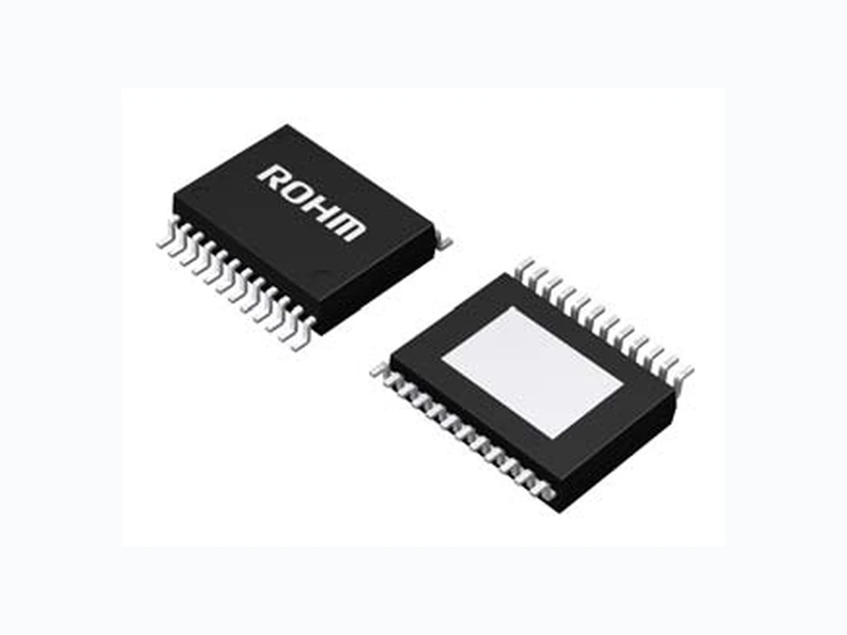
BD8226EFV_13 ROHM
Document overview
- Manufacturer or author: Provided By www.digicamel.com(FREE DATASHEET DOWNLOAD SITE)
- PDF pages: 20
Technical content
Features
■ 4CH BTL Driver ■ Has wide dynamic range ■ Built-in thermal shutdown circuit ■ Separating Vcc into Pre and Power (Power divides into CH1/2 and CH3/4) can improve efficiency. ■ Switches CH2 input using Control input terminal (CNT) ■ Incorporates mute function using CNT and MUTE terminals ■ Built-in variable regulator control
Applications
■ Power supply voltage ■ Operating temperature range ■ Maximum output amplitude PREVCC1=VPOWVCC1,2=8V, RL=8Ω) C H 1 , C H 2 C H 3 , C H 4 5.5V to 14V -40°C to +85°C 6.0V(Typ) 5.3V(Typ) P a c k a g e W(Typ) D(Typ) H(Max) HTSSOP-B24 7.80mm x 7.60mm x1.00mm HTSSOP-B24 Typical Application Circuit Figure 1. Application Circuit
TSZ02201-0G1G0C600020-1-2© 2013 ROHM Co., Ltd. All rights reserved. Figure 2. Pin Configuration Figure 3. Block Diagram
1 POWVCC1 CH1,2 power supply terminal
2 POWGND1 Power GND1
3 VO1(-) Driver CH1 negative output
4 VO1(+) Driver CH1 positive output
5 VO2(-) Driver CH2 negative output
6 VO2(+) Driver CH2 positive output
7 VO3(-) Driver CH3 negative output
8 VO3(+) Driver CH3 positive output
9 VO4(-) Driver CH4 negative output
10 VO4(+) Driver CH4 positive output
11 POWGND2 Power GND2
12 POWVCC2 CH3,4 power supply terminal
13 PREVCC PRE,REG power supply terminal
15 REG(+) Regulator terminal of output feedback
16 PREGND PRE Block and Regulator GND
17 MUTE MUTE terminal
18 IN4 CH4 input
19 IN3 CH3 input
20 BIAS BIAS input terminal
21 IN2-2 CH2-2 input
22 IN2-1 CH2-1 input
23 CNT Control input terminal
24 IN1 IN1 input
DatasheetDatasheetBD8226EFV TSZ02201-0G1G0C600020-1-2© 2013 ROHM Co., Ltd. All rights reserved. 3.JUL.2013 Rev.002 www.rohm.com TSZ22111・15・001 Absolute Maximum Ratings (Ta=25°C) Parameter Symbol Rating Unit Power Supply Voltage VPREVCC,VPOWVCC1, VPOWVCC2 15 V Input Terminal Voltage Vin1 (1) VPREVCC V Power Dissipation Pd 1.1(2) W 4.0(3) Operating Temperature Range Topr -40 to +85 °C Storage Temperature Tstg -55 to +150 °C Junction Temperature Tjmax +150 °C (1) Vin1 supplies the following terminals :IN1, CNT, IN2-1, IN2-2, BIAS, IN3, IN4, MUTE, REG(+) (2) Rated for 70mm×70mm×1.6mm, one layer substrate (back copper foil 0mm×0mm), Derated by 8.8mW/°C when operating above Ta=25°C. (3) Rated for 70mm×70mm×1.6mm, four laye r substrate (back copper foil 70mm×70mm), Derated by 32.0mW/°C when operating above Ta=25°C. Caution: Operating the IC over the absolute maximum ratings may damage th e IC. In addition, it is impossible to predict all destructive situations such as short-circuit modes, open circuit modes, etc. Therefore, it is importan t to consider circuit protection measures, like adding a fuse, in case the IC is operated in a special mode exceeding the absolute maximum ratings. Recommended Operating Ratings (Ta=-40°C to +85°C) Parameter Symbol Min Typ Max Unit PRE Driver Block Power Supply Voltage(4) V PREVCC 4.5 8.0 14 V DC Motor Driver Power Supply Voltage(4) V POWVCC1 4.5 8.0 V PREVCC V Actuator Driver Power Supply Voltage(4) V POWVCC2 4.5 8.0 V PREVCC V (4) Consider power consumption when deciding power supply voltage.
DatasheetDatasheetBD8226EFV TSZ02201-0G1G0C600020-1-2© 2013 ROHM Co., Ltd. All rights reserved. 3.JUL.2013 Rev.002 www.rohm.com TSZ22111・15・001 Parameter Symbol Limits Unit Conditions Min Typ Max Quiescent Dissipation Current IQ - 30 45 mA No load < Driver> Output Offset Voltage (CH1,2) VOOF12 -100 0 100 mV Output Offset Voltage (CH3,4) VOOF34 -50 0 50 mV Maximum Output Amplitude (CH1,2) V OM12 5.4 6.0 - V Maximum Output Amplitude (CH3,4) V OM34 4.7 5.3 - V Closed-loop Voltage Gain (CH1,2) G V12 24.0 25.7 27.4 dB Closed-loop Voltage Gain (CH3,4) G V34 15.5 17.5 19.5 dB MUTE Terminal Low Level Input Voltage VML - - 0.5 V MUTE Terminal High Level Input Voltage VMH 2.0 - - V CNT Terminal Low Level Input Voltage VCNTL - - 0.5 V CNT Terminal High Level Input Voltage VCNTH 2.0 - - V LDIN Terminal Voltage (SLED Input) V LDIN - 0.1 0.3 V CNT=’Low’ Internal Bias Voltage VBIN 1.53 1.65 1.77 V CNT=’High’ < Regulator > Output Voltage VREGOUT 4.75 5.0 5.25 V IREG=150mA Load Regulation VRL -40 0 20 mV IREG=0mA to 500mA, 5V setting Supply Voltage Regulation VVCC -40 20 80 mV V PREVCC=5.5V to 14V, 5V setting REG(+) Terminal Voltage VREGP 1.19 1.25 1.31 V
DatasheetDatasheetBD8226EFV TSZ02201-0G1G0C600020-1-2© 2013 ROHM Co., Ltd. All rights reserved. 3.JUL.2013 Rev.002 www.rohm.com TSZ22111・15・001
Application Information
- Driver Control The mute function of the driver can be used by switching the MUTE and CNT terminals to High and Low levels. The table below shows the logic. INPUT OUTPUT MUTE CNT CH1,3,4 CH2 H H ACTIVE LD ON H L ACTIVE SL ON L H MUTE LD ON L L MUTE MUTE SL : SLED LD : LOADING 2. BIAS Drop Mute If BIAS terminal (Pin 20) voltage becomes 0.7V (Typ) or less, output of all channels turns OFF. Please set it to a minimum of 1.3V for typical use. (However, the mute function doesn't work for CH2 when CNT=High. ) 3. PREVCC Drop Mute If PREVCC terminal voltage becomes 3.8V (Typ) or less, output of all channels turns OFF. If PREVCC terminal voltage becomes 4.0V (Typ) or more, output of all channels turns ON. 4. Thermal shutdown circuit (TSD) Thermal shutdown circuit is designed to turn off output of all channels when the junction temperature (Tj) reaches 175°C (Typ) (with 25°C (Typ) hysteresis). 5. Regulator Output voltage of the regulator (VREGOUT) is set according to the following expression. R2 R1VV REGPREGOUT Please disable the oscillation prevent ion beforehand, and use the capacitor connected between the regulator output (VREGOUT) and PREGND after confirming parameters such as temperature characteristics in actual operation. The power supply voltage fluctuation described in the Electrical Characteristics is obtained when VREGOUT is 5V. Please note that fluctuation bands increase from the described values if VREGOUT is set to a value bigger than 5V.
Figure 4. Regulator Block Diagram Please shorten this as much as possible.
TSZ02201-0G1G0C600020-1-2© 2013 ROHM Co., Ltd. All rights reserved. Figure 7. Typical Application Circuit
TSZ02201-0G1G0C600020-1-2© 2013 ROHM Co., Ltd. All rights reserved. Figure 8. Power Dissipation The board and the back exposure heat radiation board part of package are connected with solder. CAUTION: Pd depends on the number of the PCB layers and area. Pd values are determined through measurement.
DatasheetDatasheetBD8226EFV TSZ02201-0G1G0C600020-1-2© 2013 ROHM Co., Ltd. All rights reserved. 3.JUL.2013 Rev.002 www.rohm.com TSZ22111・15・001 Terminal Equivalent Circuit (with typical resistance and capacitance values)
TSZ02201-0G1G0C600020-1-2© 2013 ROHM Co., Ltd. All rights reserved. Figure 9. PCB Schematic
DatasheetDatasheetBD8226EFV TSZ02201-0G1G0C600020-1-2© 2013 ROHM Co., Ltd. All rights reserved. 3.JUL.2013 Rev.002 www.rohm.com TSZ22111・15・001 Operational Notes 1. Reverse Connection of Power Supply Connecting the power supply in reverse polarity can damage the IC. Take precautions against reverse polarity when connecting the power supply, such as mounting an external diode between the power supply and the IC’s power supply terminals. 2. Power Supply Lines Design the PCB layout pattern to provide low impedanc e ground and supply lines. Separate the ground and supply lines of the digital and analog blocks to prevent noise in the ground and supply lines of the digital block from affecting the analog block. Furthermore, connect a capacitor to gr ound at all power supply pins. Consider the effect of temperature and aging on the capacitance value when using electrolytic capacitors. 3. Ground Voltage Ensure that no pins are at a voltage below that of the ground pin at any time, even during transient condition. However, pins that drive inductive loads (e.g. motor driver outputs, DC-DC converte r outputs) may inevitably go below ground due to back EMF or electromotive force. In such cases, the user should make sure that such voltages going below ground will not cause the IC and the system to malfunction by exam ining carefully all relevant factors and conditions such as motor characteristics, supply voltage, operating frequency and PCB wiring to name a few. 4. Ground Wiring Pattern When using both small-signal and large-current ground traces, the two ground traces should be routed separately but connected to a single ground at the refe rence point of the application board to avoid fluctuations in the small-signal ground caused by large currents. Also ensure that the ground traces of external components do not cause variations on the ground voltage. The power supply and ground lines must be as short and thick as possible to reduce line impedance. 5. Thermal Consideration Should by any chance the power dissipation rating be exceed ed the rise in temperature of the chip may result in deterioration of the properties of the ch ip. The absolute maximum rating of the Pd stated in this specification is when the IC is mounted on a 70mm x 70mm x 1.6mm glass epox y board. In case of exceeding this absolute maximum rating, increase the board size and copper area to prevent exceeding the Pd rating. 6. Recommended Operating Conditions These conditions represent a range within which the ex pected characteristics of the IC can be approximately obtained. The electrical characteristics are guaranteed under the conditions of each parameter. 7. Rush Current When power is first supplied to the IC, it is possible that the internal logic may be unstable and inrush current may flow instantaneously due to the internal powering sequence and delays, especially if the IC has more than one power supply. Therefore, give special consi deration to power coupling capacitance, power wiring, width of ground wiring, and routing of connections. 8. Operation Under Strong Electromagnetic Field Operating the IC in the presence of a strong electromagnetic field may cause the IC to malfunction. 9. Testing on Application Boards When testing the IC on an application board, connecting a capacitor directly to a low-impedance output pin may subject the IC to stress. Always dischar ge capacitors completely after each process or step. The IC’s power supply should always be turned off completely before connecting or removing it from the test setup during the inspection process. To prevent damage from static discharge, ground the IC during assembly and use similar precautions during transport and storage. 10. Inter-pin Short and Mounting Errors Ensure that the direction and position are correct when mounting the IC on the PCB. Incorrect mounting may result in damaging the IC. Avoid nearby pins being shorted to each other especially to ground. Inter-pin shorts could be due to many reasons such as metal particles, water droplets (i n very humid environment) and unintentional solder bridge deposited in between pins during assembly to name a few.
TSZ02201-0G1G0C600020-1-2© 2013 ROHM Co., Ltd. All rights reserved. the power supply or ground line.
- Regarding the Input Pin of the IC
When GND > Pin A and GND > Pin B, the P-N junction operates as a parasitic diode. When GND > Pin B, the P-N junction operates as a parasitic transistor. Figure 14. Example of monolithic IC structure temperature and the decrease in nominal capacitance due to DC bias and others.
- Area of Safe Operation (ASO)
- Thermal Shutdown Circuit (TSD)
the TSD threshold, the circuits are automatically restored to normal operation.
DatasheetDatasheetBD8226EFV TSZ02201-0G1G0C600020-1-2© 2013 ROHM Co., Ltd. All rights reserved. 3.JUL.2013 Rev.002 www.rohm.com TSZ22111・15・001
Ordering Information
EFV : HTSSOP-B24 Packaging and forming specification E2: Embossed tape and reel (HTSSOP-B24) Marking Diagram HTSSOP-B24 (TOP VIEW) D8226EFV Part Number Marking LOT Number PIN 1 MARK
DatasheetDatasheetBD8226EFV TSZ02201-0G1G0C600020-1-2© 2013 ROHM Co., Ltd. All rights reserved. 3.JUL.2013 Rev.002 www.rohm.com TSZ22111・15・001 Physical Dimension, Tape and Reel Information Package Name HTSSOP-B24 ∗ Order quantity needs to be multiple of the minimum quantity. <Tape and Reel information> Embossed carrier tape (with dry pack)Tape Quantity Direction of feed The direction is the 1pin of product is at the upper left when you hold reel on the left hand and you pull out the tape on the right hand 2000pcs Direction of feed Reel 1pin
DatasheetDatasheetBD8226EFV TSZ02201-0G1G0C600020-1-2© 2013 ROHM Co., Ltd. All rights reserved. 3.JUL.2013 Rev.002 www.rohm.com TSZ22111・15・001
Revision History
3.JUL.2013 002 New Release
Notice - GE Rev.002 © 2014 ROHM Co., Ltd. All rights reserved. Notice Precaution on using ROHM Products 1. Our Products are designed and manufac tured for application in ordinary electronic equipments (such as AV equipment, OA equipment, telecommunication equipment, home electroni c appliances, amusement equipment, etc.). If you intend to use our Products in devices requiring ex tremely high reliability (such as medical equipment (Note 1), transport equipment, traffic equipment, aircraft/spacecraft, nuclear power controllers, fuel controllers, car equipment including car accessories, safety devices, etc.) and whose malfunction or failure may cause loss of human life, bodily injury or serious damage to property (“Specific Applications”), please consult with the ROHM sale s representative in advance. Unless otherwise agreed in writing by ROHM in advance, RO HM shall not be in any way responsible or liable for any damages, expenses or losses incurred by you or third parties arising from the use of any ROHM’s Products for Specific Applications. (Note1) Medical Equipment Classification of the Specific Applications JAPAN USA EU CHINA CLASSⅢ CLASSⅢ CLASSⅡb CLASSⅢ CLASSⅣ CLASS Ⅲ 2. ROHM designs and manufactures its Products subject to strict quality control system. However, semiconductor products can fail or malfunction at a certain rate. Please be sure to implement, at your own responsibilities, adequate safety measures including but not limited to fail-safe desi gn against the physical injury, damage to any property, which a failure or malfunction of our Products may cause. The following are examples of safety measures: [a] Installation of protection circuits or other protective devices to improve system safety [b] Installation of redundant circuits to reduce the impact of single or multiple circuit failure 3. Our Products are designed and manufactured for use under standard conditions and not under any special or extraordinary environments or conditio ns, as exemplified below. Accordin gly, ROHM shall not be in any way responsible or liable for any damages, expenses or losses arising from the use of an y ROHM’s Products under any special or extraordinary environments or conditions. If you intend to use our Products under any special or extraordinary environments or conditions (as exemplified bel ow), your independent verification and confirmation of product performance, reliability, etc, prior to use, must be necessary: [a] Use of our Products in any types of liquid, including water, oils, chemicals, and organic solvents [b] Use of our Products outdoors or in places where the Products are exposed to direct sunlight or dust [c] Use of our Products in places where the Products ar e exposed to sea wind or corrosive gases, including Cl 2, H2S, NH3, SO2, and NO2 [d] Use of our Products in places where the Products are exposed to static electricity or electromagnetic waves [e] Use of our Products in proximity to heat-producing components, plastic cords, or other flammable items [f] Sealing or coating our Products with resin or other coating materials [g] Use of our Products without cleaning residue of flux (ev en if you use no-clean type fluxes, cleaning residue of flux is recommended); or Washing our Products by using water or water-soluble cleaning agents for cleaning residue after soldering [h] Use of the Products in places subject to dew condensation 4. The Products are not subjec t to radiation-proof design. 5. Please verify and confirm characteristics of the final or mounted products in using the Products. 6. In particular, if a transient load (a large amount of load applied in a short per iod of time, such as pulse. is applied, confirmation of performance characteristics after on-boar d mounting is strongly recomm ended. Avoid applying power exceeding normal rated power; exceeding the power rating under steady-state loading condition may negatively affect product performance and reliability. 7. De-rate Power Dissipation (Pd) depending on Ambient temper ature (Ta). When used in sealed area, confirm the actual ambient temperature. 8. Confirm that operation temperat ure is within the specified range described in the product specification. 9. ROHM shall not be in any way responsible or liable for fa ilure induced under deviant condi tion from what is defined in this document. Precaution for Mounting / Circuit board design 1. When a highly active halogenous (chlori ne, bromine, etc.) flux is used, the residue of flux may negatively affect product performance and reliability. 2. In principle, the reflow soldering method must be used; if flow soldering met hod is preferred, please consult with the ROHM representative in advance. For details, please refer to ROHM Mounting specification
Notice - GE Rev.002 © 2014 ROHM Co., Ltd. All rights reserved. Precautions Regarding Application Examples and External Circuits 1. If change is made to the constant of an external circuit, pl ease allow a sufficient margin c onsidering variations of the characteristics of the Products and external components, including transient characteri stics, as well as static characteristics. 2. You agree that application notes, re ference designs, and associated data and in formation contained in this document are presented only as guidance for Products use. Theref ore, in case you use such information, you are solely responsible for it and you must exercise your own independent verification and judgment in the use of such information contained in this document. ROHM shall not be in any way responsible or liable for any damages, expenses or losses incurred by you or third parties arising from the use of such information. Precaution for Electrostatic This Product is electrostatic sensitive product, which may be damaged due to electrostatic discharge. Please take proper caution in your manufacturing process and storage so that voltage exceeding t he Products maximum rating will not be applied to Products. Please take special care under dry condit ion (e.g. Grounding of human body / equipment / solder iron, isolation from charged objects, setting of Ionizer, friction prevention and temperature / humidity control). Precaution for Storage / Transportation 1. Product performance and soldered connections may deteriora te if the Products are stored in the places where: [a] the Products are exposed to sea winds or corros ive gases, including Cl2, H2S, NH3, SO2, and NO2 [b] the temperature or humidity exceeds those recommended by ROHM [c] the Products are exposed to di rect sunshine or condensation [d] the Products are exposed to high Electrostatic 2. Even under ROHM recommended storage c ondition, solderability of products out of recommended storage time period may be degraded. It is strongly recommended to confirm sol derability before using Products of which storage time is exceeding the recommended storage time period. 3. Store / transport cartons in the co rrect direction, which is indicated on a carton with a symbol. Otherwise bent leads may occur due to excessive stress applied when dropping of a carton. 4. Use Products within the specified time after opening a hum idity barrier bag. Baking is required before using Products of which storage time is exceeding the recommended storage time period. Precaution for Product Label QR code printed on ROHM Products label is for ROHM’s internal use only. Precaution for Disposition When disposing Products please dispose them properly using an authorized industry waste company. Precaution for Foreign Exchange and Foreign Trade act Since our Products might fall under cont rolled goods prescribed by the applicable foreign exchange and foreign trade act, please consult with ROHM representative in case of export. Precaution Regarding Intellectual Property Rights 1. All information and data including but not limited to application example contain ed in this document is for reference only. ROHM does not warrant that foregoi ng information or data will not infringe any intellectual property rights or any other rights of any third party regarding such information or data. ROHM shall not be in any way responsible or liable for infringement of any intellectual property rights or other damages arising from use of such information or data.: 2. No license, expressly or implied, is granted hereby under any intellectual property rights or other rights of ROHM or any third parties with respect to the information contained in this document. Other Precaution 1. This document may not be reprinted or reproduced, in whol e or in part, without prior written consent of ROHM. 2. The Products may not be disassembled, converted, modified, reproduced or otherwise changed without prior written consent of ROHM. 3. In no event shall you use in any wa y whatsoever the Products and the related technical information contained in the Products or this document for any military purposes, incl uding but not limited to, the development of mass-destruction weapons. 4. The proper names of companies or products described in this document are trademarks or registered trademarks of ROHM, its affiliated companies or third parties.
Notice – WE Rev.001 © 2014 ROHM Co., Ltd. All rights reserved. General Precaution 1. Before you use our Pro ducts, you are requested to care fully read this document and fully understand its contents. ROHM shall n ot be in an y way responsible or liabl e for failure, malfunction or acci dent arising from the use of a ny ROHM’s Products against warning, caution or note contained in this document. 2. All information contained in this docume nt is current as of the issuing date and subj ec t to change without any prior notice. Before purchasing or using ROHM’s Products, please confirm the la test information with a ROHM sale s representative. 3. The information contained in this doc ument is provi ded on an “as is” basis and ROHM does not warrant that all information contained in this document is accurate an d/or error-free. ROHM shall not be in an y way responsible or liable for any damages, expenses or losses incurred by you or third parties resulting from inaccuracy or errors of or concerning such information.
Minimum Package Quantity 2000 Packing Type Taping Constitution Materials List inquiry RoHS Yes BD8226EFV - Web Page Distribution Inventory