

 Download PDF
ADS1148EVM TI1
Document overview
- PDF pages: 34
Technical content
Page 1
User's Guide
ADS1148EVM, ADS1248EVM, ADS1148EVM-PDK, and
ADS1248EVM-PDK
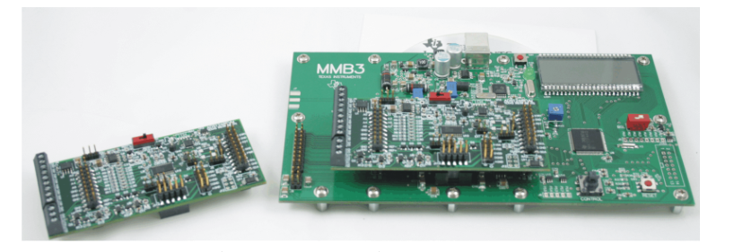
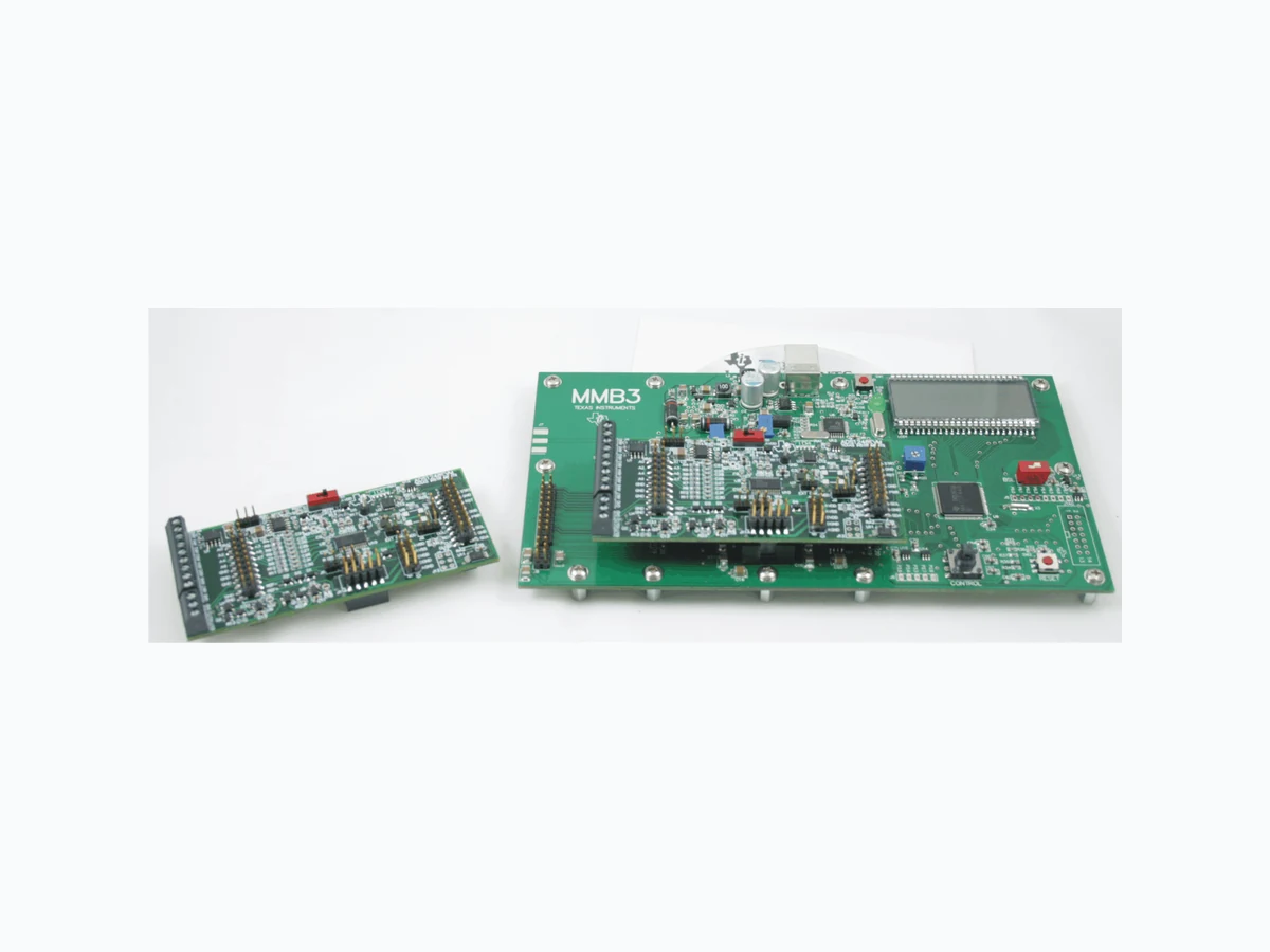
ADS1248EVM (Left) and ADS1248EVM-PDK (Right)
This user's guide describes the characteristics,
operation, and use of the ADS1148EVM and
ADS1248EVM, both by themselves and as part of the ADS1148EVM-PDK or ADS1248EVM-PDK. These evaluation modules (EVMs) are evaluation boards for the ADS1248, a 24-bit, multi-channel, delta-sigma analog-to-digital converter (ADC), and the ADS1148, a 16-bit version of the ADS1248. This EVM allows evaluation of all aspects of the ADS1148 or ADS1248 devices. Complete circuit descriptions, schematic diagrams, and bills of material are included in this document. The following related documents are available for download through the Texas Instruments web site at http://www.ti.com.
EVM-Compatible Device Data Sheets
| Column 1 | Column 2 |
|---|---|
| Device | Literature Number |
| ADS1148 | SBAS453 |
| ADS1248 | SBAS426A |
| REF5020 | SBOS410D |
| OPA227 | SBOS110A |
| TPS3836L30 | SLVS292D |
| TPS79225 | SLVS337B |
| TPS72325 | SLVS346B |
| SN74LVC2G157 | SCES207K |
| PCA9535 | SCPS129I |
ADCPro is a trademark of Texas Instruments. Microsoft, Windows are registered trademarks of Microsoft Corporation. I2C is a trademark of NXP Semiconductors. All other trademarks are the property of their respective owners.
Page 2
Contents
EVM Overview ............................................................................................................... 3 1 Analog Interface ............................................................................................................. 3 2 Digital Interface .............................................................................................................. 4 3 Power Supplies .............................................................................................................. 5 4 Voltage Reference .......................................................................................................... 6 5 Clock Source ................................................................................................................ 6
6 EVM Operation .............................................................................................................. 7 7 ADS1248EVM-PDK Kit Operation ........................................................................................ 8 8 Evaluating Performance with the ADCPro Software .................................................................. 17 9 10 Schematics and Layout ................................................................................................... 29
List of Figures
Reference Select Switch S1............................................................................................... 1
6
Jumper J2.................................................................................................................... 2
7
ADS1248EVM Default Jumper Locations................................................................................ 3
8
Virtual COM Port Installer.................................................................................................. 4
9
Virtual COM Port Setup .................................................................................................... 5
9
MMB3 Switch Locations .................................................................................................. 6
10
Connecting ADS1248EVM to MMB3 ................................................................................... 7
11
MMB3 Block Diagram..................................................................................................... 8
12
ADCPro Software Start-up Display Window ........................................................................... 9
13
ADS1248EVM-PDK Plug-In Display Window.......................................................................... 10
14
11 Connection Timeout.......................................................................................................
15
Firmware Download Message Box...................................................................................... 12
15
Firmware Download Progress Indicator ................................................................................ 13
16
Firmware Download Complete Message Box ......................................................................... 14
17
ADS1248 Multiplexer...................................................................................................... 15
18
16 I/O Config Tab .............................................................................................................
19
Enabling VBIAS on a Channel........................................................................................... 17
20
GPIO Tab................................................................................................................... 18
21
GPIO Set to Output Mode................................................................................................ 19
22
GPIO Output Set to High................................................................................................. 20
23
21 Power & Ref Tab ..........................................................................................................
24
Cal Tab ..................................................................................................................... 22
26
About Tab .................................................................................................................. 23
27
Progress Bar While Collecting Data .................................................................................... 24
28
List of Tables
J8/J4: Analog Interface Pinout ............................................................................................ 1
4
J7: Serial Interface Pins.................................................................................................... 2
4
J11 Configuration: Power-Supply Input .................................................................................. 3
5
J10 Configuration: Power Options........................................................................................ 4
5
REF1 Reference Voltage Options ........................................................................................ 5
6
List of Switches.............................................................................................................. 6
8
ADS1148EVM/ADS1248EVM Bill of Materials ....................................................................... 7
29
Page 3
EVM Overview
1 EVM Overview
1.1 Features
ADS1148EVM/ADS1248EVM Features:
- Contains all support circuitry needed for the ADS1148/ADS1248
- ±2.5V and +5V power-supply options for ADC
- Voltage reference options: external or onboard
- GPIO access
- Compatible with the TI Modular EVM System ADS1148EVM-PDK/ADS1248EVM-PDK Features:
- Easy-to-use evaluation software for Microsoft® Windows® XP
- Data collection to text files
- Built-in analysis tools including scope, FFT, and histogram displays
- Complete control of board settings
- Easily expandable with new analysis plug-in tools from Texas Instruments For use with a computer, the ADS1148EVM-PDK or ADS1248EVM-PDK is available. This kit combines the ADS1148/ADS1248EVM board with the MSP430-based MMB3 motherboard, and includes ADCPro™ software for evaluation. The MMB3 motherboard allows the ADS1148/ADS1248EVM to be connected to the computer via an available USB port. This manual shows how to use the MMB3 as part of the ADS1148EVM-PDK/ADS1248EVM-PDK, but does not provide technical details about the MMB3 itself. ADCPro is a program for collecting, recording, and analyzing data from ADC evaluation boards. It is based on a number of plug-in programs, so it can be expanded easily with new test and data collection plug-ins. The ADS1148EVM-PDK/ADS1248EVM-PDK is controlled by a plug-in that runs in ADCPro. For more information about ADCPro, see the ADCPro™ Analog-to-Digital Converter Evaluation Software User's Guide (literature number SBAU128), available for download from the TI web site. This manual covers the operation of both the ADS1148/ADS1248EVM and the ADS1148EVM-PDK/ADS1248EVM-PDK. Throughout this document, the abbreviation EVM and the term evaluation module are synonymous with the ADS1148/ADS1248EVM. For clarity of reading, the remainder of this manual will refer only to the ADS1248EVM or ADS1248EVM-PDK, but operation of the EVM and kit for the ADS1148 is identical, unless otherwise noted.
1.2 Introduction The ADS1248EVM is an evaluation module built to the TI Modular EVM System specification. It can be connected to any modular EVM system interface card. The ADS1248EVM is available as a stand-alone printed circuit board (PCB) or as part of the ADS1248EVM-PDK, which includes an MMB3 motherboard and software. As a stand-alone PCB, the ADS1248EVM is useful for prototyping designs and firmware. Note that the ADS1248EVM has no microprocessor and cannot run software. To connect it to a computer, some type of interface is required.
2 Analog Interface For maximum flexibility, the ADS1248EVM is designed for easy interfacing to multiple analog sources. Samtec part numbers SSW-110-22-F-D-VS-K and TSM-110-01-T-DV-P provide a convenient 10-pin, dual-row, header/socket combination at J8. This header/socket provides access to the analog input pins of the ADS1248. Consult Samtec at http://www.samtec.com or call 1-800-SAMTEC-9 for a variety of mating connector options. These signals can also be connected to the terminal block J4.
Page 4
Digital Interface
All of the pins on J4 and J8 are connected with minimal filtering or protection. Use appropriate caution
when handling these pins. Table 1 summarizes the pinouts for analog interfaces J4 and J8.
Table 1. J8/J4: Analog Interface Pinout
| Pin Number | Signal | Description, ADS1148/ADS1248 |
|---|---|---|
| J8.1, J4-1 | A0(–) | AIN0 |
| J8.2, J4-2 | A0(+) | AIN1 |
| J8.3, J4-3 | A1(–) | AIN2 |
| J8.4, J4-4 | A1(+) | AIN3 |
| J8.5, J4-5 | A2(–) | AIN4 |
| J8.6, J4-6 | A2(+) | AIN5 |
| J8.7, J4-7 | A3(–) | AIN6 |
| J8.8, J4-8 | A3(+) | AIN7 |
| J8.18 | REF– | External reference source input (– side of differential input) |
| J8.20 | REF+ | External reference source input (+ side of differential input) |
| J8.10-16 (even) | Unused | |
| J8.15 | Unused | |
| J8.9-19 (odd), J4-9 | AGND | Analog ground connections (except J8.15) |
3
Digital Interface
3.1 Serial Data Interface
The ADS1248EVM is designed to easily interface with multiple control platforms. Samtec part numbers
SSW-110-22-F-D-VS-K and TSM-110-01-T-DV-P provide a convenient 10-pin, dual-row, header/socket
combination at J7. This header/socket provides access to the digital control and serial data pins of the
ADC. Consult Samtec at http://www.samtec.com or call 1-800-SAMTEC-9 for a variety of mating
connector options.
All logic levels on J7 are 3.3V CMOS, except for the I2C™ pins. These pins conform to 3.3V I2C rules.
Table 2 describes the J7 serial interface pins.
Table 2. J7: Serial Interface Pins
| Pin No. | Pin Name | Signal Name | I/O Type | Pullup | Function |
|---|---|---|---|---|---|
| J7.1 | CNTL | CS | In | High | |
| J7.2 | GPIO0 | START | In | High | |
| J7.3 | CLKX | SCLK | In | None | ADS1248 SPI clock |
| J7.4 | DGND | DGND | In/Out | None | Digital ground |
| J7.5 | CLKR | Unused | – | – | |
| J7.6 | GPIO1 | MR | In | High | Master reset |
| J7.7 | FSX | Unused | – | – | |
| J7.8 | GPIO2 | Unused | – | – | |
| J7.9 | FSR | DRDY | Out | None | |
| J7.10 | DGND | DGND | In/Out | None | Digital ground |
| J7.11 | DX | DIN | In | None | ADS1248 SPI data in |
| J7.12 | GPIO3 | PWRSEL | In | High | Selects ±2.5V or +5V supply |
| J7.13 | DR | DOUT/DRDY | Out | None | ADS1248 data out |
| J7.14 | GPIO4 | Unused | – | – | |
| J7.15 | INT | DRDY | Out | None |
Page 5
Power Supplies
Table 2. J7: Serial Interface Pins (continued)
| Pin No. | Pin Name | Signal Name | I/O Type | Pullup | Function |
|---|---|---|---|---|---|
| J7.16 | SCL | SCL | I2C | High | I2C clock |
| J7.17 | TOUT | CLK | In | None | Can be used to provide a clock from a processor |
| J7.18 | DGND | DGND | In/Out | None | Digital ground |
| J7.19 | GPIO5 | CLK Select | – | None | |
| J7.20 | SDA | SDA | I2C | High | I2C data |
Many pins on J7 have weak pull-up resistors. These resistors provide default settings for many of the
control pins. Many pins on J7 correspond directly to ADS1248 pins. See the ADS1248 product data sheet
for complete details on these pins.
4
Power Supplies
J11 is the power-supply input connector. Table 3 lists the configuration details for J11.
Table 3. J11 Configuration: Power-Supply Input
| Column 1 | Column 2 | Column 3 | Column 4 |
|---|---|---|---|
| Pin No. | Pin Name | Function | Required |
| J11.1 | +VA | Unused | No |
| J11.2 | –VA | Unused | No |
| J11.3 | +5VA | +5V analog supply | Always |
| J11.4 | –5VA | –5V analog supply | Only in bipolar mode |
| J11.5 | DGND | Digital ground input | Yes |
| J11.6 | AGND | Analog ground input | Yes |
| J11.7 | +1.8VD | 1.8V digital supply | No |
| J11.8 | VD1 | Unused | No |
| J11.9 | +3.3VD | 3.3V digital supply | Always |
| J11.10 | +5VD | +5V digital supply | No |
All of the power supplies (AVDD, AVSS, and DVDD) have corresponding jumpers on J10 that can be
replaced with a current meter to measure the respective supply currents.
4.1 Power Options
J10 is arranged as five rows, each of which can be shorted. Table 4 lists the power option details for J10.
For normal operation, J10.1-2, J10.3-4, and J10.5-6 must be connected (direct or through an ammeter),
and either (or both) of J10.7-8 and J10.9-10 must be connected; otherwise, the board does not function.
Table 4. J10 Configuration: Power Options
| Column 1 | Column 2 | Column 3 |
|---|---|---|
| Row | Name | Function |
| 1-2 | ADC AVDD | AVDD supply current measurement point for the ADC. Must be connected for operation. |
| 3-4 | ADC AVSS | AVSS supply current measurement point for the ADC. Must be connected for operation. |
| 5-6 | ADC DVDD | DVDD supply current measurement point for the ADC. Must be connected for operation. |
| 7-8 | DGND | Connects DGND to board ground. |
| 9-10 | AGND | Connects AGND to board ground. |
Page 6
Voltage Reference
5 Voltage Reference The ADS1248 device has the option of selecting between three different references: REF0, REF1, and the internal reference, through registers in the ADS1248 chip. The EVM provides a 2.048V reference for REF1 from U1, filtered and buffered through U2. This 2.048V may be used to drive the REF1P input. REF1P should not be connected to AVDD through switch S1 because this connection will violate the specification for the maximum reference input. Figure 1 shows switch S1 as it appears on the EVM. The low side of the reference (REF1N) is tied to AVSS.The different reference options under different supply conditions are outlined in Table 5.
Figure 1. Reference Select Switch S1
Table 5. REF1 Reference Voltage Options
| Column 1 | Column 2 | Column 3 | Column 4 | Column 5 | Column 6 | Column 7 |
|---|---|---|---|---|---|---|
| AVDD | AVSS | J1 Setting | S1 Position (1) | REF1P | REF1N | REF1 Reference Voltage |
| 5V | 0V | 1-2 | BUFF | 2.048V | 0V | 2.048V |
| 5V | 0V | 2-3 | BUFF | 0V | 0V | Invalid selection |
| 2.5V | –2.5V | 1-2 | BUFF | –0.452V | –2.5V | 2.048V |
| 2.5V | –2.5V | 2-3 | BUFF | 0V | –2.5V | 2.5V |
Switch S1 should not be set to AVDD. (1)
The REF0N and REF0P pins are connected directly to the external reference pins on J8.18 and J8.20, respectively. These pins are diode-clamped to AVDD and AVSS, and protected with D3, a 5.1V zener. If the external reference pins are not supplied with a external source, REF0N will be at approximately AVSS + 0.6V, and REF0P will be at approximately AVDD–0.6V. The internal reference voltage can be measured between testpoints TP3 (Int REF) and TP5 (REFCOM).
6 Clock Source The ADS1248 has an internal clock or can be provided an external clock. The EVM uses the internal clock mode only. Provision is made on the EVM circuit board, however, for an external clock source. A footprint is provided at U8 for a crystal oscillator to be mounted on the board. An external clock may also be provided by a processor on the TOUT pin (J7.17), or an external clock source connected to J14.1 (ground) and J14.2 (signal). J2 controls how the clock source is selected. With pins J2.1 and J2.2 shorted, GPIO5 from J7.19 can control whether the A or B side of U7 is selected. If the A side is selected, the clock should come from an external source provided as described above. If the B side is selected, the clock should come from the
crystal oscillator. If a selection is made and no clock is provided on that input, the ADS1248 detects that no external clock is present and enables its internal oscillator.
6.1 Usage in PDK If using the ADS1248EVM as part of the ADS1248EVM-PDK, J14 should have a jumper installed. Remove any shorting blocks on jumper J13, and make sure J2 has a jumper between pins 1 and 2 (the IO position). This configuration grounds the CLK input to the ADS1248 and ensures that the internal oscillator starts up.
Page 7
EVM Operation
6.2 Usage as a Stand-Alone EVM If using the EVM in your own system and not with the PDK hardware and software, observe the following recommendations:
- J13 should be removed if the external clock source is used and the TOUT pin is still driven by a processor in order to avoid conflicts.
- Jumper J2 can be used to always select the U8 oscillator (DVDD position) or allow the onboard/external clock selection to be controlled by GPIO5 (J7.19) as shown in Figure 2.
Figure 2. Jumper J2
7 EVM Operation This section provides information on the analog input, digital control, and general operating conditions of the ADS1248EVM.
7.1 Analog Input Each of the analog input sources can be applied directly to J8 (top or bottom side) or through signal-conditioning modules available for the the modular EVM system. Terminal block J4 is connected in parallel with the analog signal connections to J8. Each input has a 47Ω/47pF RC filter in series with it, and a differential 0.1μF capacitor is placed across each input pair for use with differential signals.
7.2 Digital Control The digital control signals can be applied directly to J7 (top or bottom side). The modular ADS1248EVM can also be connected directly to a DSP or microcontroller interface board, such as the 5-6K Interface or HPA-MCU Interface boards available from Texas Instruments, or the MMB3 if purchased as part of the ADS1248EVM-PDK. For a list of compatible interface and/or accessory boards for the EVM or the ADS1248, see the relevant product folder on the TI web site.
Page 8
ADS1248EVM-PDK Kit Operation 7.3 Default Jumper Settings and Switch Positions Figure 3 shows the jumpers found on the EVM and the respective factory default conditions for each.
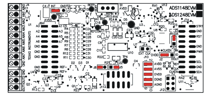
Figure 3. ADS1248EVM Default Jumper Locations
Table 6 lists the switches found on the EVM and the respective factory default conditions for each.
Table 6. List of Switches
| Switch | Default Position | Switch Description |
|---|---|---|
| S1 | Left | Onboard reference |
8 ADS1248EVM-PDK Kit Operation This section provides information on using the ADS1248EVM-PDK, including setup, program installation, and program usage. To prepare to evaluate the ADS1248 with the ADS1248EVM-PDK, complete the following steps: Step 1. Install the ADCPro software (if not already installed) on a PC. Step 2. Install the ADS1248EVM-PDK EVM plug-in software. Step 3. Complete the USB driver installation process. Step 4. Set up the ADS1248EVM-PDK. Step 5. Connect the ADS1248EVM-PDK to the computer with a USB cable. Step 6. Run the ADCPro software. Each task is described in the subsequent sections of this document.
Page 9
ADS1248EVM-PDK Kit Operation
8.1 Installing the ADCPro Software

The CD-ROM shipped with the ADS1248EVM contains an installer for ADCPro as well as an installer for the ADS1248EVM plug-in. The latest software is available from the TI website at http://www.ti.com/. Refer to the ADCPro User Guide for instructions on installing and using ADCPro. To install the ADS1248EVM-PDK plug-in, run the file: ads1248evm-pdk-plug-in-1.0.0.exe (1.0.0 is the version number, and increments with software version releases; you may have a different version on your CD). Double-click the file to run it; then follow the instructions shown. You can also utilize the ADCPro Update Check feature to check for newer versions of the ADS1248EVM-PDK plug-in, once you have
installed a version of it. Follow the on-screen prompts. Once the ADCPro plug-in installs, you will be prompted to install the Virtual COM port driver as shown in Figure 4.
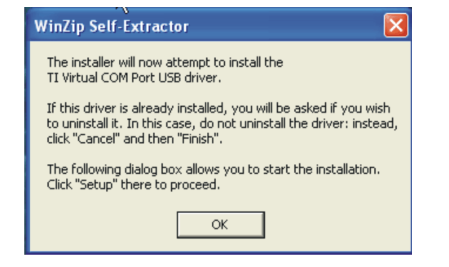
Figure 4. Virtual COM Port Installer
Press OK, and the screen shown in Figure 5 is displayed.
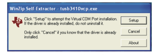
Figure 5. Virtual COM Port Setup
If you already have a TUSB3410 Virtual COM port driver installed on your system, select Cancel; otherwise, press Setup and follow the on-screen prompts. You may be notified that the driver is not digitally signed. If this message appears, select Continue Anyway and proceed.
Page 10
ADS1248EVM-PDK Kit Operation 8.2 Setting Up the ADS1248EVM-PDK The ADS1248EVM-PDK contains both the ADS1248EVM and the MMB3 motherboard; however, the devices are shipped unconnected. Follow these steps to set up the ADS1248EVM-PDK. Step 1. Unpack the ADS1248EVM-PDK kit. Step 2. Set the switches on the MMB3 as described below, as shown in Figure 6.
- Set switch SW4 to the right.
- Set the DAC switch (SW5) to the OUT position (to the right).
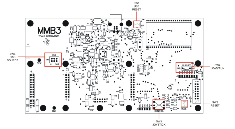
Figure 6. MMB3 Switch Locations
Step 3. Plug the ADS1248EVM into the MMB3 as Figure 7 illustrates.
Page 11
ADS1248EVM-PDK Kit Operation
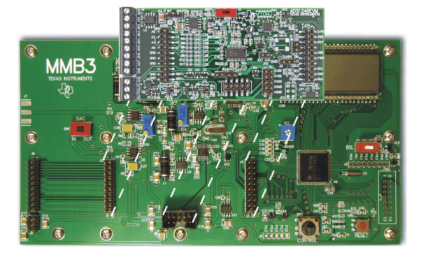
Figure 7. Connecting ADS1248EVM to MMB3

Step 4. Set the jumpers and switches on the ADS1248EVM as shown in Figure 3 (note that these settings are the factory-configured settings for the EVM).
8.2.1 About the MMB3 The MMB3 is a Modular EVM System motherboard. It is designed around the MSP430F449, a low-power microcontroller from Texas Instruments. Figure 8 shows a block diagram of the MMB3.
Page 12
ADS1248EVM-PDK Kit Operation
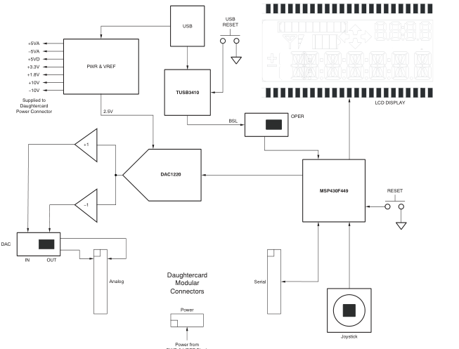
PWR & VREF Block Figure 8. MMB3 Block Diagram
The MMB3 was designed to be used as a stand-alone demonstration platform for low-speed data converters. It features an onboard, 20-bit digital-to-analog converter (DAC) that can be used as a signal source for an ADC under test, and has a joystick for control of functions on the board when it is not controlled by a PC. These features are experimental and not supported in the ADS1248EVM-PDK at this time. The MMB3 derives power from the USB interface, and generates +5VD, 3.3V, and 1.8V, as well as +5VA and –5VA and ±10V. The ±10V is supplied to the daughtercard power connector as +VA and –VA. The MMB3 is not sold as a microcontroller development board, and it is not available separately. TI cannot
offer support for the MMB3 except as part of an EVM kit. For schematics or other information about the MMB3, contact Texas Instruments.
8.3 EVM Power Supply The ADS1248EVM-PDK is powered completely from the USB connection on the MMB3. The MMB3 provides 3.3V and ±5V to the ADS1248EVM.
8.4 Running the Software and Download of Firmware to MMB3
The software is continually under development. These instructions and screen images are
NOTE:
current at the time of this writing, but may not exactly match future releases.
The program for evaluating the ADS1248EVM-PDK is called ADCPro. This program uses plug-ins to communicate with the EVM. The ADS1248EVM-PDK plug-in is included in the ADS1248EVM-PDK package.
Page 13
ADS1248EVM-PDK Kit Operation
The program currently runs only on Microsoft Windows platforms of Windows XP; Windows Vista is NOT supported. If this is the first time installing ADCPro and plug-ins, follow these procedures to run ADCPro and perform any necessary firmware installations. Make sure the ADCPro software and device plug-in software are installed from the CD-ROM as described in Section 8.1, Installing the ADCPro Software. Step 1. Start the software by selecting ADCPro from the Windows Start menu. The screen in Figure 9 appears.
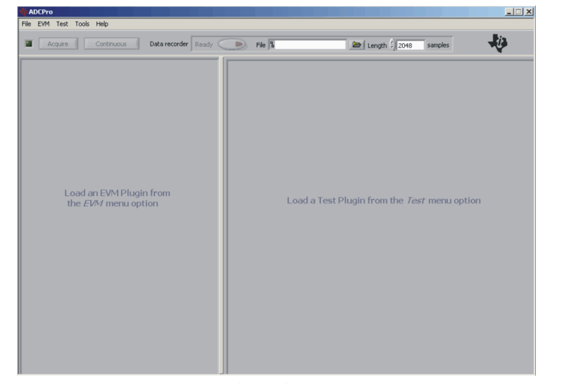
Figure 9. ADCPro Software Start-up Display Window
Page 14
ADS1248EVM-PDK Kit Operation
break Step 2. Select ADS1248EVM from the EVM drop-down menu. The ADS1248EVM-PDK plug-in appears in the left pane, as shown in Figure 10.
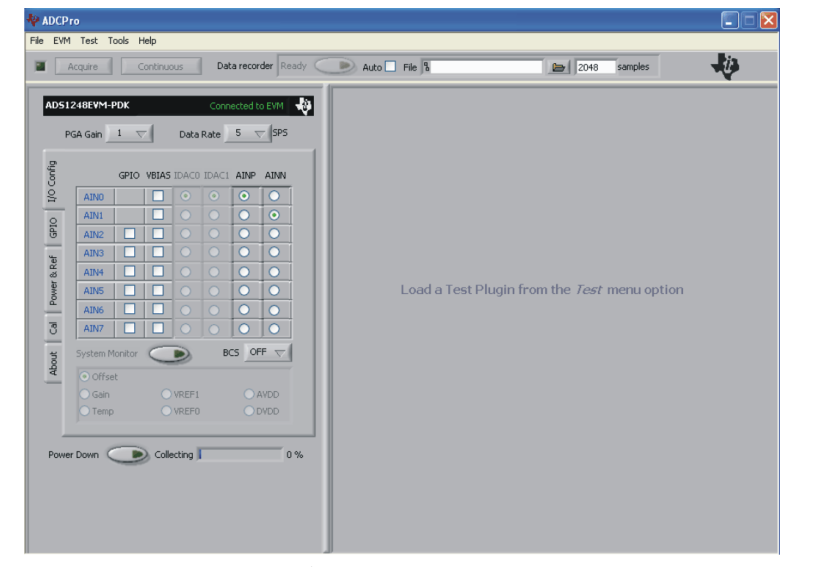
Figure 10. ADS1248EVM-PDK Plug-In Display Window
Step 3. The ADS1248EVM-PDK plug-in window has a status area at the top of the screen. When the plug-in is first loaded, the plug-in searches for the board. You will see a series of messages in the status area indicating this action.
Page 15
ADS1248EVM-PDK Kit Operation
break Step 4. If the plug-in cannot connect to the EVM, you will see a window as shown in Figure 11. This message may indicate that the firmware is not loaded on the MMB3. You may select Retry Auto Connect; if that action fails, select Retry Manual Connect and specify the COM port to be used.
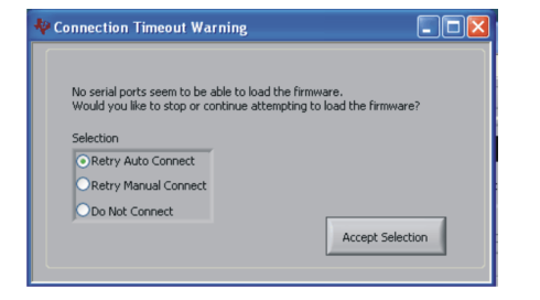
Figure 11. Connection Timeout
Step 5. The plug-in detects whether or not the board has the correct firmware loaded. The first time you use the ADS1248EVM-PDK, the firmware for the MMB3 may need to be downloaded to the MMB3. If the firmware needs to be loaded, you will see a screen as shown in Figure 12.
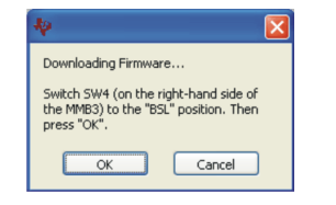
Figure 12. Firmware Download Message Box
Page 16
ADS1248EVM-PDK Kit Operation
Switch the BSL switch (SW4) on the MMB3 to the BSL position (to the left) as instructed, then press OK. The plug-in will download the firmware to the MMB3. This operation may take a couple of minutes, so the progress is updated in the message at the top of the ADS1248 plug-in window (as Figure 13 shows). The firmware is saved in flash memory on the MMB3, so this operation should only need to be performed once.
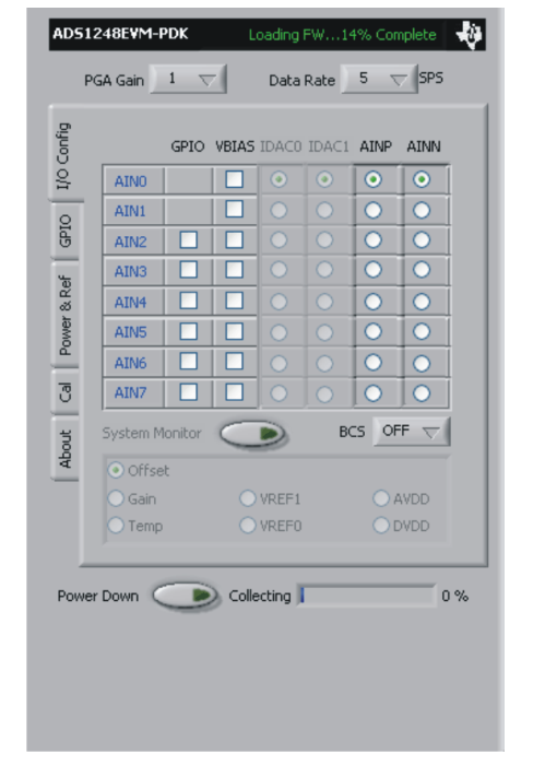
Figure 13. Firmware Download Progress Indicator
Page 17
Evaluating Performance with the ADCPro Software
When the firmware download completes, the message box shown in Figure 14 appears. Follow the on-screen instructions and the plug-in should now connect to the EVM.
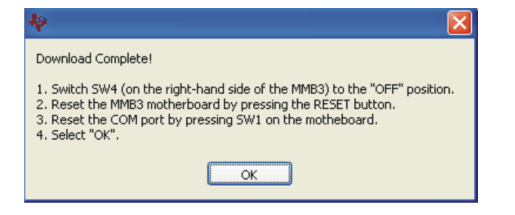
Figure 14. Firmware Download Complete Message Box
Evaluating Performance with the ADCPro Software 9 The evaluation software is based on ADCPro, a program that operates using a variety of plug-ins. To use ADCPro, load an EVM plug-in and a test plug-in. To load an EVM plug-in, select it from the EVM menu. To load a test plug-in, select it from the Test menu. To unload a plug-in, select the Unload option from the corresponding menu. Only one of each kind of plug-in can be loaded at a time. If you select a different plug-in, the previous plug-in is unloaded.
9.1 Using the ADS1248EVM-PDK Plug-in The ADS1248EVM-PDK plug-in for ADCPro provides complete control over all settings of the ADS1248. It consists of a tabbed interface (see Figure 16), with different functions available on different tabs. These controls are described in this section. You can adjust the ADS1248EVM settings when you are not acquiring data. During acquisition, all controls are disabled and settings may not be changed. When you change a setting on the ADS1248EVM plug-in, the setting immediately updates on the board. Settings on the ADS1248EVM correspond to settings described in the ADS1248 data sheet (available for download at www.ti.com) for details.
The ADS1248EVM-PDK plug-in has a tabbed interface, with five different tabs to control the functions of the ADS1248. These tabs are described below.
Page 18
Evaluating Performance with the ADCPro Software
9.1.1 I/O Config Tab
This tab is the primary tab that controls the function of the multiplexer in the ADS1248. Recall that the
ADS1248 multiplexer is configured as shown in Figure 15. By default, all channels are set as analog
inputs; the IDACs are not routed to any channel and the IDAC controls are disabled. These controls are
enabled when the correct IDAC settings are made on the Power & Ref tab (see Section 9.1.3).
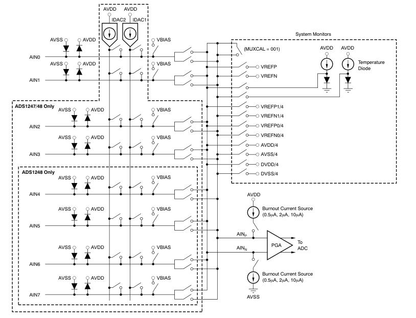
Figure 15. ADS1248 Multiplexer
The radio buttons at the far right of the panel (see Figure 16) select which pair of inputs are connected to
the PGA. Note that you may select the same input for both the positive (AINP) and negative (AINN) input;
this configuration is often selected to perform a noise test on the ADC itself.
Page 19
Evaluating Performance with the ADCPro Software
Input pins AIN2-AIN7 can be selected to be an analog input or GPIO. If an input is to be used as a GPIO, check the GPIO box as shown in Figure 16.
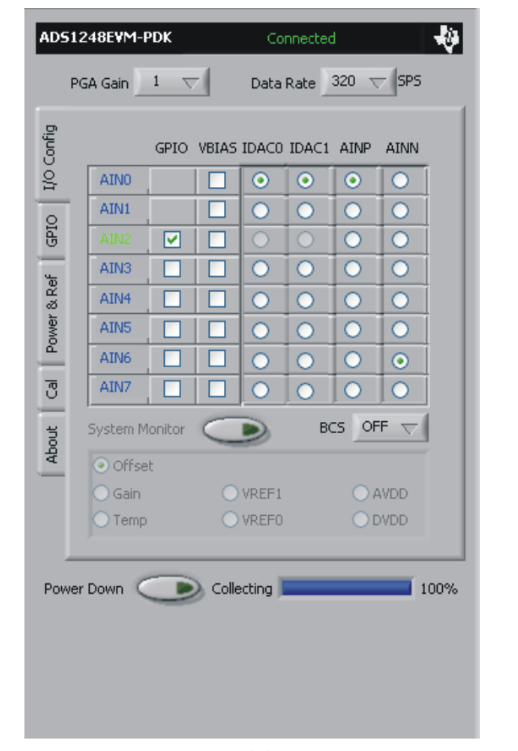
Figure 16. I/O Config Tab
When an input is selected as a GPIO, its label turns green and the IDAC controls for that channel are disabled.
Page 20
Evaluating Performance with the ADCPro Software
Each input channel can also have a VBIAS applied to it. Checking the VBIAS box on a channel applies the VBIAS voltage, which is approximately half the value of the supply. You can test this option as shown in Figure 17, using one channel tied to a value close to ground (make sure you observe the common-mode restrictions listed in the ADS1248 product data sheet) as a reference for this signal.
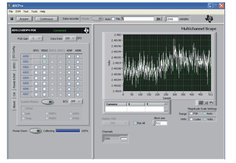
Figure 17. Enabling VBIAS on a Channel
The System Monitor button allows you to access the internal system monitor channels of the ADS1248. When pressed, this button disables the other analog input channel controls, and the system monitor channel selections are enabled. You can select Offset, Gain, Temperature, VREF1, VREF0, AVDD, or DVDD as the channel to convert. Note that some of these channels are scaled by a factor when read; refer to the ADS1248 product data sheet to determine these factors. The PGA Gain control sets the PGA gain, and the Data Rate control sets the data rate for the device. Note that the data rate can go quite low; therefore, if the block size is large, the time it takes to collect a
block of data can be quite long. It is advisable to first test collection at the higher data rates. Once a test is known to work properly, drop to a lower data rate and allow sufficient time to collect the data. The BCS control sets the current level of the burnout current sources; it may be set to Off, or to 0.5μA, 2μA, or 10μA. The Power Down control powers down the ADS1248. Note that no data can be collected if the Power Down button is activated.
Page 21
Evaluating Performance with the ADCPro Software
9.1.2 GPIO Tab When an input is selected to be a GPIO, its controls are enabled on the GPIO tab, shown in Figure 18. By default, the GPIOs are enabled as inputs. Pressing the Input button reads the state of the enabled inputs; if the input is high, the corresponding light turns green.
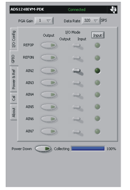
Figure 18. GPIO Tab
Page 22
Evaluating Performance with the ADCPro Software
To make the GPIO an output, the toggle switch can be switched to output mode, as shown in Figure 19.
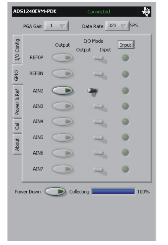
Figure 19. GPIO Set to Output Mode
Page 23
Evaluating Performance with the ADCPro Software
With the GPIO configured as an output, the pushbutton switch controls the state of the output pin. When pressed (as illustrated in Figure 20), the button lights up and the GPIO is set to a high state; when the switch is dark (as Figure 19 shows), the GPIO is in a low state.
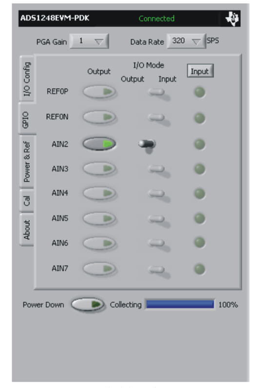
Figure 20. GPIO Output Set to High
Page 24
Evaluating Performance with the ADCPro Software
9.1.3 Power & Ref Tab The Power & Ref tab is shown in Figure 21. This tab controls the selection of the power-supply mode, reference sources, and IDACs.
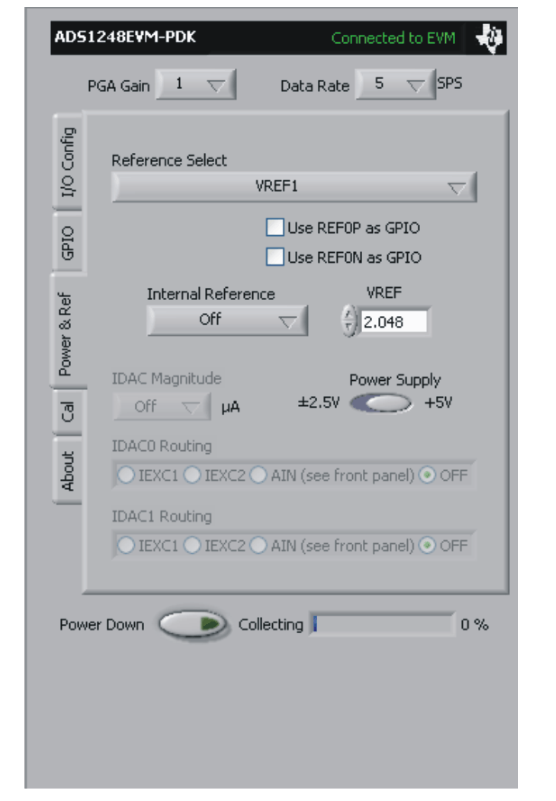
Figure 21. Power & Ref Tab
Note that with the Internal Reference off, the IDAC controls are disabled, because the IDACs cannot be used unless the internal reference is turned on.
Page 25
Evaluating Performance with the ADCPro Software
The Power Supply control selects between single supply (+5V) mode and bipolar supply (±2.5V) mode. The EVM draws its supply voltages from the MMB3 motherboard, and has onboard circuitry to select between the +5V and bipolar supplies. The Reference Select control selects between VREF0, VREF1, and the Internal Reference. When VREF1 is selected, the VREF value is set to 2.048V, with switch S1 set to BUFF. S1 should not be set to the AVDD position, in order to prevent the reference from exceeding the maximum specified input. There are two checkboxes that, when enabled, allow the REF0P and REF0N pins to be selected as GPIOs. These checkboxes are enabled only in modes that allow these pins to be used as GPIOs.
The Internal Reference control selects whether the reference is off, on, or follows the START signal (refer to the ADS1248 data sheet for more details on these choices). When the internal reference is enabled, the IDAC controls are enabled as well, because the IDACs cannot function unless the internal reference is turned on. Note that the internal reference does not necessarily have to be used as the ADC reference in order to use the IDACs, but it does need to be turned on. The IDAC Magnitude control sets the amount of current each of the two IDACs provide. The IDAC0 and IDAC 1 Routing controls allow you to specify where the IDAC0 or IDAC1 current go: to
either the IEXC1 or IEXC2 pins, or to the Analog inputs, or you may turn the IDAC off. If the AIN button is selected, this option enables the corresponding IDAC controls on the I/O Config tab.
Page 26
Evaluating Performance with the ADCPro Software
9.1.4 Cal Tab The Cal tab (Figure 22) controls the calibration functions of the ADS1248.
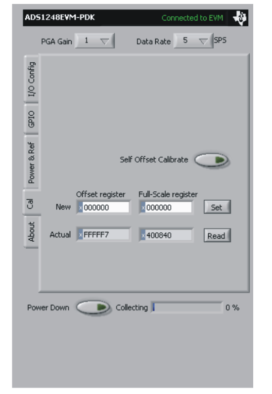
Figure 22. Cal Tab
Pressing the Self Offset Calibrate button causes the ADS1248 to perform a self calibration; the offset and full-scale register values are then updated on the plug-in screen. You may also write to these registers by typing in hex values in the New fields, then press the Set button. You may read the values at any time by pressing the Read button.
Page 27
Evaluating Performance with the ADCPro Software
9.1.5 About Tab The About tab displays information about the EVM and software, as shown in Figure 23.
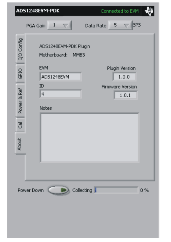
Figure 23. About Tab
The Plugin Version and Firmware Version indicators show the version numbers of the plug-in and firmware code, respectively. The ID indicator shows the value of the ID [3:0] bits in the ADS1248 ID register. The Notes indicator may show relevant notes about the plug-in or firmware code, if there are any.
Page 28
Evaluating Performance with the ADCPro Software
9.1.6 Collecting Data Once you have configured the ADS1248 for your test scenario, press the ADCPro Acquire button to start the collection of the number of datapoints specified in the Test plug-in Block Size control. The ADS1248EVM-PDK plug-in disables all the front panel controls while acquiring, and displays a progress bar as shown in Figure 24.
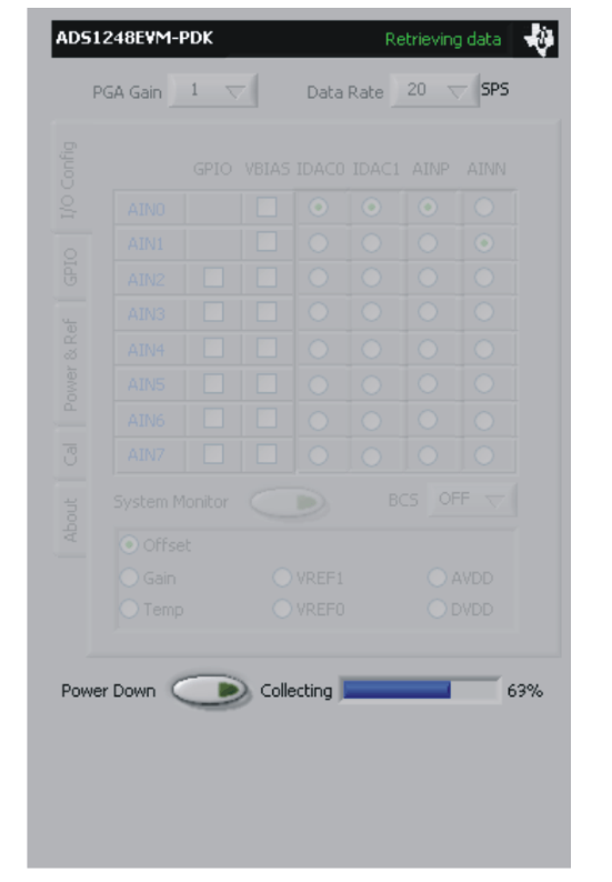
Figure 24. Progress Bar While Collecting Data
For more information on testing analog-to-digital converters in general and using ADCPro and test plug-ins, refer to the ADCPro User Guide.
Page 29
Schematics and Layout
9.2 Troubleshooting
If the ADS1248EVM plug-in cannot find the ADS1248EVM-PDK, press the USB RESET button on the
MMB3 (refer to Figure 6) and try again.
If ADCPro stops responding while the ADS1248EVM-PDK is connected, try unplugging the USB cable
from the PDK. Unload and reload the plug-in before reapplying power to the PDK.
10 Schematics and Layout
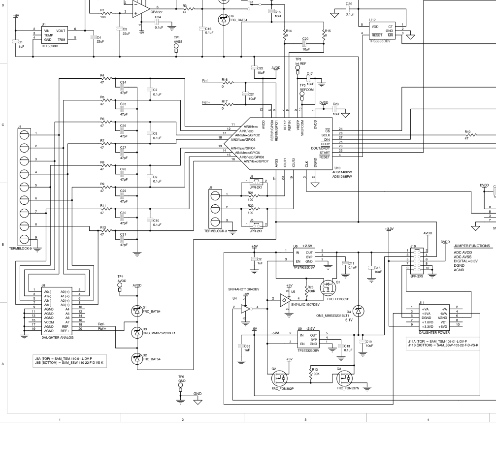
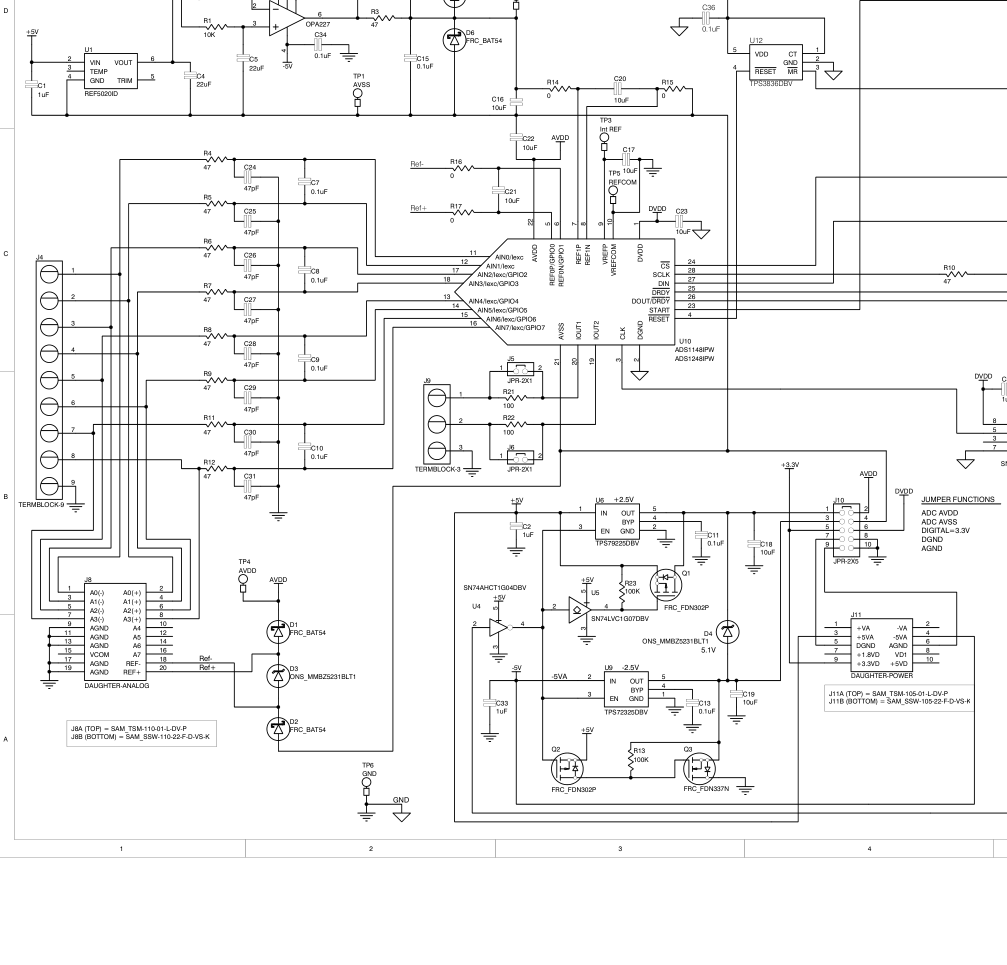
Schematics for the ADS1148EVM and ADS1248EVM are appended to this user's guide. The bill of
materials is provided in Table 7.
10.1 Bill of Materials
NOTE: All components should be compliant with the European Union Restriction on Use of
Hazardous Substances (RoHS) Directive. Some part numbers may be either leaded or
RoHS. Verify that purchased components are RoHS-compliant. (For more information about
TI's position on RoHS compliance, see the Quality and Eco-Info information on the TI web
site.)
Table 7. ADS1148EVM/ADS1248EVM Bill of Materials
| Item No. | Qty | Value | Ref Des | Description | Vendor | Part Number |
|---|---|---|---|---|---|---|
| 1 | 1 | N/A | ADS1248 EVM PWB | Texas Instruments | 6496961 | |
| 2 | 4 | 1μF | C1-C3, C33 | Capacitor, X7R Ceramic 1μF ±10%, 16WV, Size = 0603 | TDK | C1608X7R1C105KT |
| 3 | 2 | 22μF | C4, C5 | Capacitor, X5R Ceramic 22μF ±20%, 16WV, Size = 1210 | TDK | C3225X5R1C226MT |
| 4 | 12 | 0.1μF | C6-C13, C15, C34, C35, C36 | Capacitor, X7R Ceramic 0.1μF ±10%, 25WV, Size = 0603 | TDK | C1608X7R1E104KT |
| 5 | 1 | 0.15μF | C14 | Capacitor, X7R Ceramic 0.15μF ±10%, 16WV, Size = 0603 | Murata | GRM188R71C154KA 01D |
| 6 | 8 | 10μF | C16-C23 | Capacitor, X5R Ceramic 10μF ±20%, 6.3WV, Size = 0805 | TDK | C2012X5R0J106MT |
| 7 | 8 | 47pF | C24-C31 | Capacitor, C0G Ceramic 47pF ±5%, 50WV, Size = 0603 | TDK | C1608C0G1H470JT |
| 8 | 1 | 10nF | C32 | Capacitor, C0G Ceramic 10nF ±5%, 25WV, Size = 0603 | TDK | C1608C0G1E103JT |
| 9 | 4 | D1, D2, D5, D6 | DIODE SCHOTTKY 30V 200MA SOT-23 | Fairchild | BAT54 | |
| 10 | 2 | D3, D4 | 5.1V, Zener Diode | On Semiconductor | MMBZ5231BLT1G | |
| 11 | 2 | J1, J2 | Header Strip, 3-pin ( ) | Samtec | TSW-103-07-L-S | |
| 12 | 1 | J4 | Terminal Block, 9-position | On Shore Technology | ED555/9DS | |
| 13 | 4 | J5, J6, J13, J14 | Header Strip, 2-pin ( ) | Samtec | TSW-102-07-L-S | |
| 14 | 2 | J7A, J8A | 20-pin SMT Plug | Samtec | TSM-110-01-L-DV-P | |
| 15 | 2 | J7B, J8B | 20-pin SMT Socket | Samtec | SSW-110-22-F-D-VS- K | |
| 16 | 1 | J9 | Terminal Block, 3 position | On Shore Technology | ED555/3DS | |
| 17 | 1 | J10 | Header Strip, 10-pin ( ) | Samtec | TSW-105-07-L-D | |
| 18 | 1 | J11A | 10-pin SMT Plug | Samtec | TSM-105-01-L-DV-P | |
| 19 | 1 | J11B | 10-pin SMT Socket | Samtec | SSW-105-22-F-D-VS- K | |
| 20 | 0 | J12 | Header Strip, 6-pin ( ) | |||
| 21 | 2 | Q1, Q2 | MOSFET, P-Channel, 2.5V | Fairchild | FDN302P | |
| 22 | 1 | Q3 | Enhancement Mode FET, N-Channel | Fairchild | FDN337N | |
| 23 | 1 | 100kΩ | RA1 | Resistor, 8 Thick Film Chip Array 100kΩ, 5%, 63mW | CTS | 745C101104JPTR |
Page 30
Revision History
Table 7. ADS1148EVM/ADS1248EVM Bill of Materials (continued)
| Item No. | Qty | Value | Ref Des | Description | Vendor | Part Number |
|---|---|---|---|---|---|---|
| 24 | 0 | RA2 | Resistor, Chip Array 4 Independent Bus 100kΩ, 5%, 1/16W, SMD | |||
| 25 | 1 | 10kΩ | R1 | Resistor, Thick Film Chip 10kΩ, 5%, 1/10W, Size = 0603 | Panasonic | ERJ-3GEYJ103V |
| 26 | 1 | 2kΩ | R2 | Resistor, Thick Film Chip 2kΩ, 1%, 1/16W, Size = 0603 | Panasonic | ERJ-3EKF2001V |
| 27 | 10 | 47Ω | R3-R12 | Resistor, Thick Film Chip 47Ω, 5%, 1/10W, Size = 0603 | Panasonic | ERJ-3GEYJ470V |
| 28 | 2 | 100kΩ | R13, R23 | Resistor, Thick Film Chip 100kΩ, 5%, 1/10W, Size = 0603 | Panasonic | ERJ-3GEYJ104V |
| 29 | 4 | 0Ω | R14, R15, R16, R17 | Resistor, Thick Film Chip 0Ω, 5%, 1/10W, Size = 0603 | Panasonic | ERJ-3GEY0R00V |
| 30 | 1 | 47kΩ | R18 | Resistor, Thick Film Chip 47kΩ, 5%, 1/10W, Size = 0603 | Panasonic | ERJ-3GEYJ473V |
| 31 | 2 | 470kΩ | R19, R20 | Resistor, Thick Film Chip 470kΩ, 5%, 1/10W, Size = 0603 | Panasonic | ERJ-3GEYJ474V |
| 32 | 2 | 100Ω | R21, R22 | Resistor, Thick Film Chip 100Ω, 5%, 1/10W, Size = 0603 | Panasonic | ERJ-3GEYJ101V |
| 33 | 2 | 2.7kΩ | R24, R25 | Resistor, Thick Film Chip 2.7kΩ, 5%, 1/10W, Size = 0603 | Panasonic | ERJ-3GEYJ272V |
| 34 | 1 | S1 | Switch, Mini Slide, SPDT | NKK | SS12SDP2 | |
| 35 | 0 | TP1-TP5 | PCB Test Point, Mini Loop, Through-Hole | |||
| 36 | 1 | TP6 | PCB Test Point, Large Loop, Through-Hole | Keystone Electronics | 5011 | |
| 37 | 1 | U1 | Precision Voltage Reference, 2.048V | Texas Instruments | REF5020ID | |
| 38 | 1 | U2 | Precision Operational Amplifier | Texas Instruments | OPA227U | |
| 39 | 1 | U3 | 16-Bit I2C I/O Expander | Texas Instruments | PCA9535RGE | |
| 40 | 1 | U4 | Inverter, Single Gate | Texas Instruments | SN74AHCT1G04DBV R | |
| 41 | 1 | U5 | Buffer, Open Drain, Single Gate | Texas Instruments | SN74LVC1G07DBVR G4 | |
| 42 | 1 | U6 | LDO Voltage Regulator, 2.5V, 100mA | Texas Instruments | TPS79225DBVRG4 | |
| 43 | 1 | U7 | Single, 2-Line to 1 Data Selector/Multiplexer | Texas Instruments | SN74LVC2G157DCT | |
| 44 | 0 | U8 | 3.3 V Oscillator | |||
| 45 | 1 | U9 | LDO Voltage Regulator, 2.5V, 200mA | Texas Instruments | TPS72325DBVTG4 | |
| 46 | 1 | U10 | Precision Delta-Sigma ADC, 24-bit/16-bit | Texas Instruments | ADS1248IPW/ADS11 48IPW | |
| 47 | 1 | U11 | EEPROM, 1.8V, 256k | Microchip | 24AA256-I/ST | |
| 48 | 1 | U12 | Supervisor, 2.64V Threshold | Texas Instruments | TPS3836L30DBVT | |
| 49 | 10 | N/A | Shorting Blocks | Samtec | SNT-100-BK-T |
Revision History
Changes from A Revision (July, 2009) to B Revision .................................................................................................... Page
- Updated Table 3 .......................................................................................................................... 5
NOTE: Page numbers for previous revisions may differ from page numbers in the current version.
Revision History
Page 31
AVDD
Page 32
AVDD
Page 33
Evaluation Board/Kit Important Notice
Texas Instruments (TI) provides the enclosed product(s) under the following conditions: This evaluation board/kit is intended for use for ENGINEERING DEVELOPMENT, DEMONSTRATION, OR EVALUATION PURPOSES ONLY and is not considered by TI to be a finished end-product fit for general consumer use. Persons handling the product(s) must have electronics training and observe good engineering practice standards. As such, the goods being provided are not intended to be complete in terms of required design-, marketing-, and/or manufacturing-related protective considerations, including product safety and environmental measures typically found in end products that incorporate such semiconductor
components or circuit boards. This evaluation board/kit does not fall within the scope of the European Union directives regarding electromagnetic compatibility, restricted substances (RoHS), recycling (WEEE), FCC, CE or UL, and therefore may not meet the technical requirements of these directives or other related directives. Should this evaluation board/kit not meet the specifications indicated in the User’s Guide, the board/kit may be returned within 30 days from the date of delivery for a full refund. THE FOREGOING WARRANTY IS THE EXCLUSIVE WARRANTY MADE BY SELLER TO BUYER AND IS IN LIEU OF ALL OTHER WARRANTIES, EXPRESSED, IMPLIED, OR STATUTORY, INCLUDING
ANY WARRANTY OF MERCHANTABILITY OR FITNESS FOR ANY PARTICULAR PURPOSE. The user assumes all responsibility and liability for proper and safe handling of the goods. Further, the user indemnifies TI from all claims arising from the handling or use of the goods. Due to the open construction of the product, it is the user’s responsibility to take any and all appropriate precautions with regard to electrostatic discharge. EXCEPT TO THE EXTENT OF THE INDEMNITY SET FORTH ABOVE, NEITHER PARTY SHALL BE LIABLE TO THE OTHER FOR ANY INDIRECT, SPECIAL, INCIDENTAL, OR CONSEQUENTIAL DAMAGES. TI currently deals with a variety of customers for products, and therefore our arrangement with the user is not exclusive.
TI assumes no liability for applications assistance, customer product design, software performance, or infringement of patents or services described herein. Please read the User’s Guide and, specifically, the Warnings and Restrictions notice in the User’s Guide prior to handling the product. This notice contains important safety information about temperatures and voltages. For additional information on TI’s environmental and/or safety programs, please contact the TI application engineer or visit www.ti.com/esh. No license is granted under any patent right or other intellectual property right of TI covering or relating to any machine, process, or combination in which such TI products or services might be or are used.
FCC Warning
This evaluation board/kit is intended for use for ENGINEERING DEVELOPMENT, DEMONSTRATION, OR EVALUATION PURPOSES ONLY and is not considered by TI to be a finished end-product fit for general consumer use. It generates, uses, and can radiate radio frequency energy and has not been tested for compliance with the limits of computing devices pursuant to part 15 of FCC rules, which are designed to provide reasonable protection against radio frequency interference. Operation of this equipment in other environments may cause interference with radio communications, in which case the user at his own expense will be required to take whatever measures may be required to correct this interference.
EVM Warnings and Restrictions
It is important to operate this EVM within the input voltage range of –5V to +5V and the output voltage range of 0V to +3.3V. Exceeding the specified input range may cause unexpected operation and/or irreversible damage to the EVM. If there are questions concerning the input range, please contact a TI field representative prior to connecting the input power. Applying loads outside of the specified output range may result in unintended operation and/or possible permanent damage to the EVM. Please consult the EVM User's Guide prior to connecting any load to the EVM output. If there is uncertainty as to the load specification, please contact a TI field representative.
During normal operation, some circuit components may have case temperatures greater than +30°C. The EVM is designed to operate properly with certain components above +85°C as long as the input and output ranges are maintained. These components include but are not limited to linear regulators, switching transistors, pass transistors, and current sense resistors. These types of devices can be identified using the EVM schematic located in the EVM User's Guide. When placing measurement probes near these devices during operation, please be aware that these devices may be very warm to the touch.
Mailing Address: Texas Instruments, Post Office Box 655303, Dallas, Texas 75265
Copyright © 2011, Texas Instruments Incorporated
Page 34
IMPORTANT NOTICE
Texas Instruments Incorporated and its subsidiaries (TI) reserve the right to make corrections, modifications, enhancements, improvements, and other changes to its products and services at any time and to discontinue any product or service without notice. Customers should obtain the latest relevant information before placing orders and should verify that such information is current and complete. All products are sold subject to TI’s terms and conditions of sale supplied at the time of order acknowledgment. TI warrants performance of its hardware products to the specifications applicable at the time of sale in accordance with TI’s standard warranty. Testing and other quality control techniques are used to the extent TI deems necessary to support this warranty. Except where
mandated by government requirements, testing of all parameters of each product is not necessarily performed. TI assumes no liability for applications assistance or customer product design. Customers are responsible for their products and applications using TI components. To minimize the risks associated with customer products and applications, customers should provide adequate design and operating safeguards. TI does not warrant or represent that any license, either express or implied, is granted under any TI patent right, copyright, mask work right, or other TI intellectual property right relating to any combination, machine, or process in which TI products or services are used. Information
published by TI regarding third-party products or services does not constitute a license from TI to use such products or services or a warranty or endorsement thereof. Use of such information may require a license from a third party under the patents or other intellectual property of the third party, or a license from TI under the patents or other intellectual property of TI. Reproduction of TI information in TI data books or data sheets is permissible only if reproduction is without alteration and is accompanied by all associated warranties, conditions, limitations, and notices. Reproduction of this information with alteration is an unfair and deceptive
business practice. TI is not responsible or liable for such altered documentation. Information of third parties may be subject to additional restrictions. Resale of TI products or services with statements different from or beyond the parameters stated by TI for that product or service voids all express and any implied warranties for the associated TI product or service and is an unfair and deceptive business practice. TI is not responsible or liable for any such statements. TI products are not authorized for use in safety-critical applications (such as life support) where a failure of the TI product would reasonably be expected to cause severe personal injury or death, unless officers of the parties have executed an agreement specifically governing
such use. Buyers represent that they have all necessary expertise in the safety and regulatory ramifications of their applications, and acknowledge and agree that they are solely responsible for all legal, regulatory and safety-related requirements concerning their products and any use of TI products in such safety-critical applications, notwithstanding any applications-related information or support that may be provided by TI. Further, Buyers must fully indemnify TI and its representatives against any damages arising out of the use of TI products in such safety-critical applications. TI products are neither designed nor intended for use in military/aerospace applications or environments unless the TI products are
specifically designated by TI as military-grade or "enhanced plastic." Only products designated by TI as military-grade meet military specifications. Buyers acknowledge and agree that any such use of TI products which TI has not designated as military-grade is solely at the Buyer's risk, and that they are solely responsible for compliance with all legal and regulatory requirements in connection with such use. TI products are neither designed nor intended for use in automotive applications or environments unless the specific TI products are designated by TI as compliant with ISO/TS 16949 requirements. Buyers acknowledge and agree that, if they use any non-designated
products in automotive applications, TI will not be responsible for any failure to meet such requirements. Following are URLs where you can obtain information on other Texas Instruments products and application solutions: Products
Applications
Audio
www.ti.com/audio
Communications and Telecom
Amplifiers
amplifier.ti.com
Computers and Peripherals
Data Converters
dataconverter.ti.com
Consumer Electronics
DLP® Products
www.dlp.com
Energy and Lighting
DSP
dsp.ti.com
Industrial
Clocks and Timers
www.ti.com/clocks
Medical
Interface
interface.ti.com
Security
Logic
logic.ti.com
Space, Avionics and Defense
Power Mgmt
power.ti.com
Transportation and Automotive
Microcontrollers
microcontroller.ti.com
Video and Imaging
RFID
www.ti-rfid.com
Wireless
RF/IF and ZigBee® Solutions www.ti.com/lprf
TI E2E Community Home Page
www.ti.com/communications www.ti.com/computers www.ti.com/consumer-apps www.ti.com/energy www.ti.com/industrial www.ti.com/medical www.ti.com/security www.ti.com/space-avionics-defense www.ti.com/automotive
www.ti.com/video www.ti.com/wireless-apps
e2e.ti.com
Mailing Address: Texas Instruments, Post Office Box 655303, Dallas, Texas 75265
Copyright © 2011, Texas Instruments Incorporated