
BAT42W_V01 VISHAY
Document overview
- Manufacturer or author: Provided By www.digicamel.com(FREE DATASHEET DOWNLOAD SITE)
- PDF pages: 4
Technical content
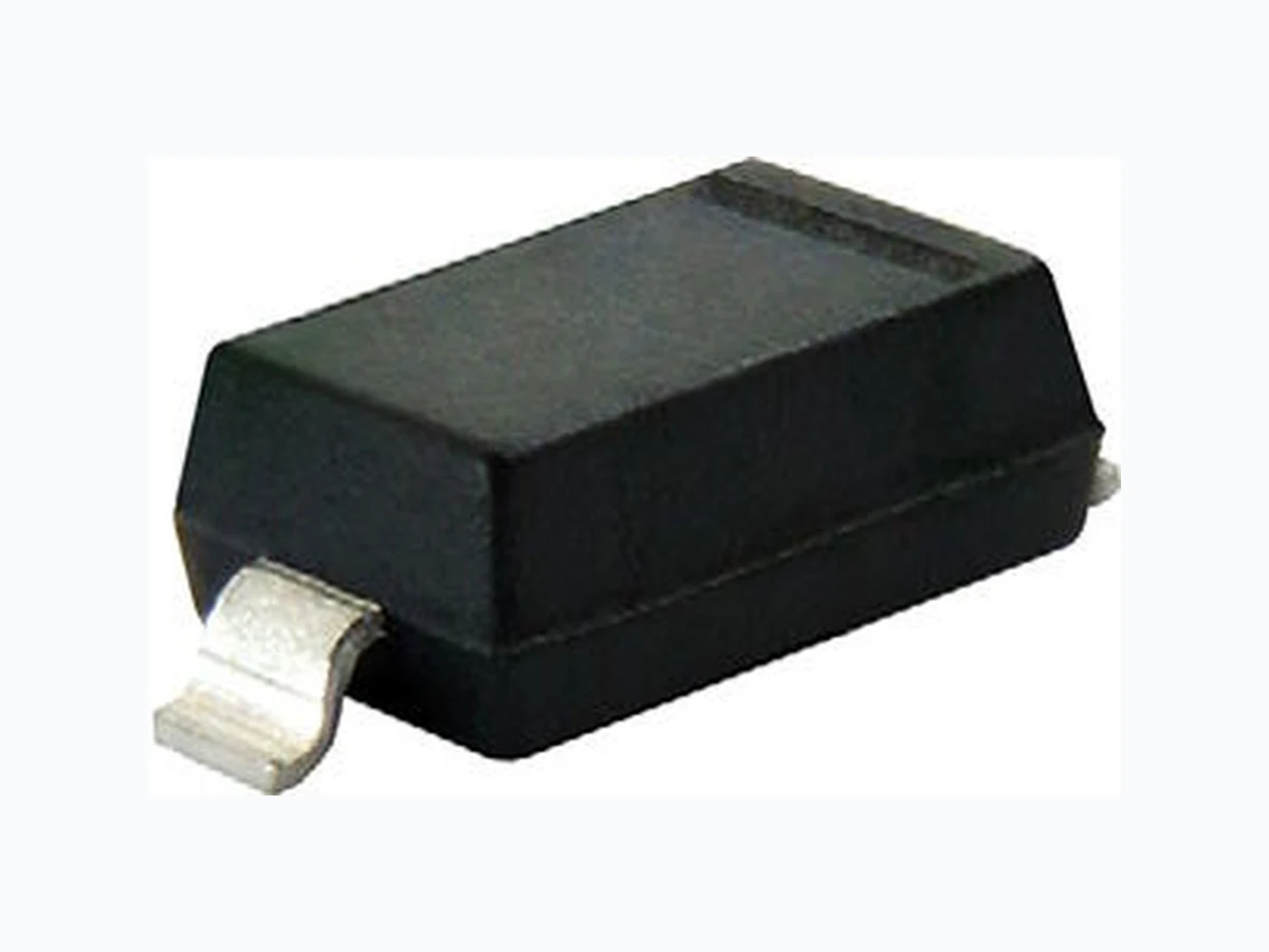
BAT42W, BAT43W www.vishay.com Vishay Semiconductors Rev. 1.9, 23-Feb-18 1 Document Number: 85661 For technical questions within your region: DiodesAmericas@vishay.com, DiodesAsia@vishay.com, DiodesEurope@vishay.com THIS DOCUMENT IS SUBJECT TO CHANGE WITHOUT NOTICE. THE PRODUCTS DESCRIBED HEREIN AND THIS DOCUMENT ARE SUBJECT TO SPECIFIC DISCLAIMERS, SET FORTH AT www.vishay.com/doc?91000 Small Signal Schottky Diode DESIGN SUPPORT TOOLS MECHANICAL DATA Case: SOD-123 Weight: approx. 10.3 mg Packaging codes/options: 18/10K per 13" reel (8 mm tape), 10K/box 08/3K per 7" reel (8 mm tape), 15K/box
FEATURES
- These diodes feature very low turn-on voltage and fast switching. These devices are protected by a PN junction guard ring against excessive voltage, such as electrostatic discharges
- For general purpose applications
- AEC-Q101 qualified available
- Base P/N-E3 - RoHS-compliant, commercial grade
- Base P/N-HE3 - RoHS-compliant, AEC-Q101 qualified
- Material categorization: fo r definitions of compliance please see www.vishay.com/doc?99912 Note (1) Valid provided that electrodes are kept at ambient temperature Note (1) Valid provided that electrodes are kept at ambient temperature click logo to get started Available Models PARTS TABLE PART ORDERING CODE CIRCUIT CONFIGURATION TYPE MARKING REMARKS BAT42W BAT42W-E3-08 or BAT42W-E3-18 Single L2 Tape and reelBAT42W-HE3-08 or BAT42W-HE3-18 BAT43W BAT43W-E3-08 or BAT43W-E3-18 Single L3BAT43W-HE3-08 or BAT43W-HE3-18 ABSOLUTE MAXIMUM RATINGS (Tamb = 25 °C, unless otherwise specified) PARAMETER TEST CONDITION SYMBOL VALUE UNIT Repetitive peak reverse voltage V RRM 30 V Forward continuous current (1) IF 200 mA Repetitive peak forward current (1) tp < 1 s, < 0.5 I FRM 500 mA Surge forward current (1) tp < 10 ms I FSM 4A Power dissipation (1) Tamb = 65 °C P tot 200 mW THERMAL CHARACTERISTICS (Tamb = 25 °C, unless otherwise specified) PARAMETER TEST CONDITION SYMBOL VALUE UNIT Thermal resistance junction to ambient air (1) RthJA 300 K/W Junction temperature T j 125 °C Operating temperature range T op -55 to +125 °C Storage temperature range T stg -55 to +150 °C
BAT42W, BAT43W www.vishay.com Vishay Semiconductors Rev. 1.9, 23-Feb-18 2 Document Number: 85661 For technical questions within your region: DiodesAmericas@vishay.com, DiodesAsia@vishay.com, DiodesEurope@vishay.com THIS DOCUMENT IS SUBJECT TO CHANGE WITHOUT NOTICE. THE PRODUCTS DESCRIBED HEREIN AND THIS DOCUMENT ARE SUBJECT TO SPECIFIC DISCLAIMERS, SET FORTH AT www.vishay.com/doc?91000 Note (1) Pulse test; tp 300 μs, tp/T < 0.02 TYPICAL CHARACTERISTICS (T amb = 25 °C, unless otherwise specified) Fig. 1 - Admissible Power Dissipation vs. Ambient Temperature Fig. 2 - Typical Forward Characteristics Fig. 3 - Typical Reverse Characteristics Fig. 4 - Typical Capacitance vs. Reverse Voltage ELECTRICAL CHARACTERISTICS (Tamb = 25 °C, unless otherwise specified) PARAMETER TEST CONDITION PART SYMBOL MIN. TYP. MAX. UNIT Reverse breakdown voltage I R = 100 μA (pulsed) V (BR) 30 V Leakage current (1) VR = 25 V I R 0.5 μA VR = 25 V, Tj = 100 °C I R 100 μA Forward voltage (1) IF = 200 mA V F 1000 mV IF = 10 mA BAT42W V F 400 mV IF = 50 mA BAT42W V F 650 mV IF = 2 mA BAT43W V F 260 330 mV IF = 15 mA BAT43W V F 450 mV Diode capacitance V R = 1 V, f = 1 MHz C D 7p F Reverse recovery time IF = 10 mA, IR = 10 mA, iR = 1 mA, RL = 100 trr 5n s 200
18442 Tamb - Ambient Temperature (°C)
Ptot - Power Dissipation (mW) 18443 120010008006004002000 I- F o rward Current (mA)F 1000 100 0.1 0.01 VF - Instantaneous Forward Voltage (mV) 25 °C 125 °C - 40 °C 1000 100 0.1 0.01 18444 0 1 02 03 04 05 0 VR - Reverse Voltage (V) 125 °C 100 °C 75 °C 50 °C 25 °C I - Re verse Leackage Current (µA)R 18445 01 02 0 3 0 VR - Reverse Voltage (V) C - Diode Capacitance (pF)D 51 5 2 5
BAT42W, BAT43W www.vishay.com Vishay Semiconductors Rev. 1.9, 23-Feb-18 3 Document Number: 85661 For technical questions within your region: DiodesAmericas@vishay.com, DiodesAsia@vishay.com, DiodesEurope@vishay.com THIS DOCUMENT IS SUBJECT TO CHANGE WITHOUT NOTICE. THE PRODUCTS DESCRIBED HEREIN AND THIS DOCUMENT ARE SUBJECT TO SPECIFIC DISCLAIMERS, SET FORTH AT www.vishay.com/doc?91000 PACKAGE DIMENSIONS in millimeters (inches): SOD-123 0.1 (0.004) max. 2.85 (0.112) 2.55 (0.100) 3.85 (0.152) 3.55 (0.140) 1.7 (0.067) 1.40 (0.055) Mounting Pad Layout 2.5 (0.098) 0.85 (0.033) Cathode bar 0.65 (0.026) 0.45 (0.018) 0.10 (0.004) 1 (0.039) 0.15 (0.006) 1.35 (0.053) 0.2 (0.008) 0° to 8° 0.45 (0.018) 0.25 (0.010) 0.5 (0.020) ref. Rev. 4 - Date: 24. Sep. 2009 Document no.: S8-V-3910.01-001 (4) 17432
www.vishay.com Vishay Revision: 01-Jan-2022 1 Document Number: 91000 Disclaimer ALL PRODUCT, PRODUCT SPECIFICATIONS AND DATA AR E SUBJECT TO CHANGE WITH OUT NOTICE TO IMPROVE RELIABILITY, FUNCTION OR DESIGN OR OTHERWISE. Vishay Intertechnology, Inc., its affiliates, agents, and employee s, and all persons acting on it s or their behalf (collectivel y, “Vishay”), disclaim any and all liability for any errors, inaccuracies or incompleteness contained in any datasheet or in any other disclosure relating to any product. Vishay makes no warranty, representation or guarantee regarding the suitability of the products for any particular purpose or the continuing production of any product. To the maximum extent permitted by applicable law, Vishay disclaims (i) any and all liability arising out of the application or use of any product , (ii) any and all liability, including without limitation specia l, consequential or incidental damages, and (iii) any and all implied warranties, incl uding warranties of fitness for particular purpose, non-infringement and merchantability. Statements regarding the suitability of pro ducts for certain types of applications are based on Vishay's knowledge of typical requirements that are often placed on Vishay products in ge neric applications. Such statements are not binding statements about the suitability of products for a particular application. It is the customer's responsibility to validate that a particular product with the properties described in the product specification is suitable for use in a particular application. Parameters provided in datasheets and / or specificat ions may vary in different applications and performance may vary over time. All operating parameters, including typical parameters, must be validated for each customer application by the customer's technical experts. Product specifications do not expand or otherwise modify Vishay's terms and conditions of purchase, including but not limited to the warranty expressed therein. Hyperlinks included in this datasheet may direct users to third-party websites. These links are provided as a convenience and for informational purposes only. Inclusion of these hyperlinks does not constitute an endorsement or an approval by Vishay of any of the products, services or opinions of the corporation, organization or individual associated with the third-party website. Vishay disclaims any and all liability and bears no responsibility for the accuracy, legality or content of the third-party web site or for that of subsequent links. Except as expressly indicated in writing, Vishay products are not designed for use in medical, life-saving, or life-sustaining applications or for any other application in which the failure of the Vishay product could result in personal injury or death. Customers using or selling Vishay products not expressly indicated for use in such applications do so at their own risk. Please contact authorized Vishay personnel to obtain written terms and conditions regarding products designed for such applications. No license, express or implied, by estoppel or otherwise, to any intellectual property rights is granted by this document or by any conduct of Vishay. Product names and markings noted herein may be trademarks of their respective owners. © 2022 VISHAY INTERTECHNOLOGY, INC. ALL RIGHTS RESERVED