

 Download PDF
DATASHEET SEARCH SITE
Document overview
- PDF pages: 3
Technical content
Page 1
BABCONNECTOR
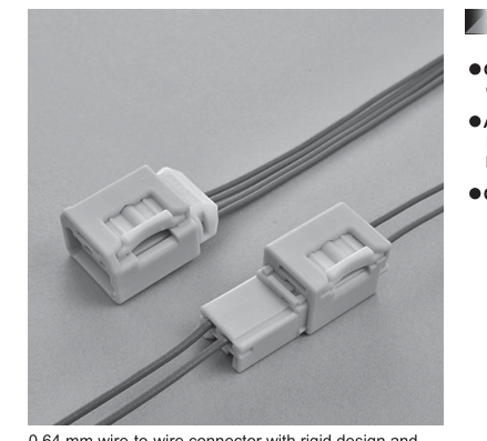
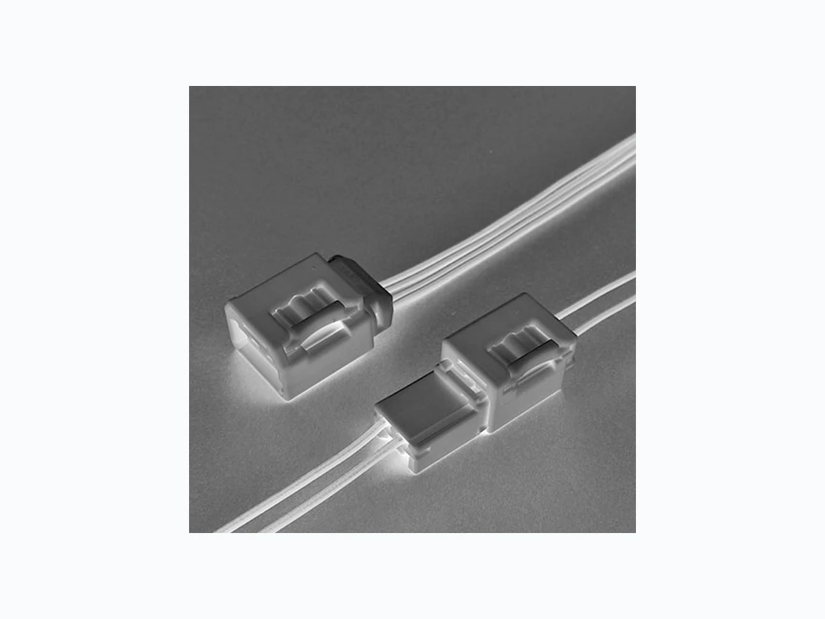
0.64 mm wire-to-wire connector with rigid design and spring lock mechanism. Spring force prevents half-mating during mating and keeps constant rigid connection between male and female connector.
Wire-to-wire
Wire-to-wire
Features
- Go / No-Go Mating System Compression spring prevents half-mating.
- Anti Vibration Mechanism High reliability rigid connector enables to keep higher durability at shock and vibration environment.
- Compact size
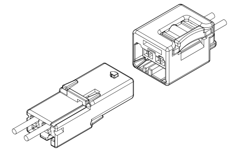
Specifications
- Current rating: 3 A AC, DC max. (0.3 mm2) 5 A AC, DC max. (0.5 mm2)
- Withstanding voltage: 1,000 VAC/minute
- Temperature range: -40°C to +80°C
(including temperature rise in applying electrical current)
- Contact resistance: Initial value/ 10 mΩ max. After environmental tests/ 20 mΩ max.
- Insulation resistance: 100 MΩ min.
- Applicable wire: AVSS 0.3 mm2 to 0.5 mm2
\* Compliant with ELV/RoHS2. \* Contact JST for details.
Page 2
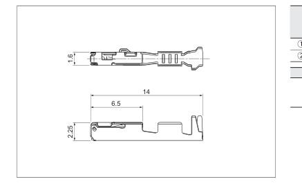
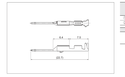
Female terminal
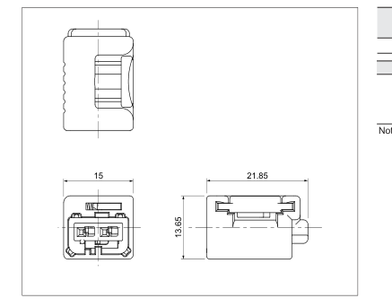
Female connector
Male terminal
BAB CONNECTOR
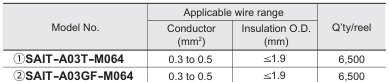
Material and Finish
ΖCopper alloy, tin-plated (reflow treatment) ΗCopper alloy, nickel-undercoated, Contact area; gold-plated Barrel area; tin-plated
| Circuits | Model No. | Q’ty/box |
| 2 | BABRB-02-1A-Y( ) | 300 |
Material and Finish Housing: PA, Yellow Retainer: Glass-filled PBT, Natural Slider: Glass-filled PBT, Natural Spring: SUS
Note: Key codes other than above-mentioned housing are also available. Contact JST for details.
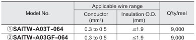
Material and Finish
①Brass, tin-plated (reflow treatment) ②Brass, nickel-undercoated, Contact area; gold-plated Barrel area; tin-plated
Page 3
BAB CONNECTOR
Male connector
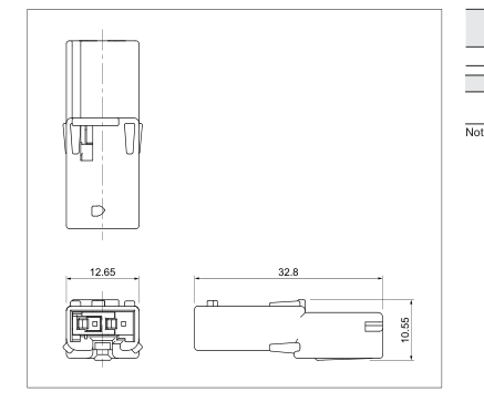
Assembly layout
| Circuits | Model No. | Q’ty/box |
| 2 | BABPB-02-1A-Y( ) | 300 |
Material and Finish Housing: PA, Yellow Retainer: PBT, Natural
Note: Key codes other than above-mentioned housing are also available. Contact JST for details.

Crimping machine, Applicator

Note: When crimping operation is conducted using an applicator and die set other than the above, JST cannot guarantee the performance of the terminal.