
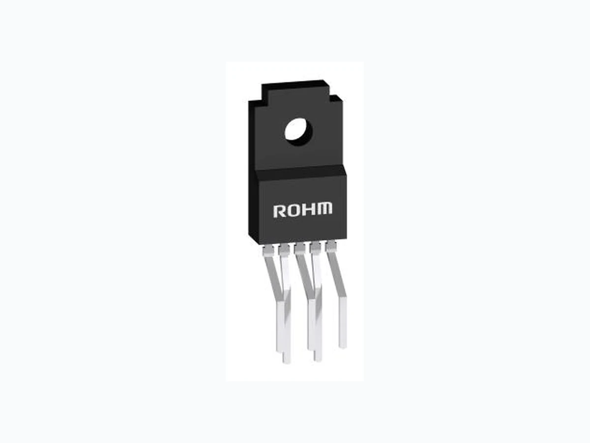
BA00DD0W ROHM
Document overview
- Manufacturer or author: Provided By www.digicamel.com(FREE DATASHEET DOWNLOAD SITE)
- PDF pages: 25
Technical content
〇Product structure : Silicon monolithic integrated circuit 〇This product is not designed protection against radioactive rays. 1/21 TSZ02201-0R6R0A600080-1-2 5.Sep.2018 Rev.004 TSZ22111・14・001 © 2012 ROHM Co., Ltd. All rights reserved. www.rohm.com 2A/1A Variable Output LDO Regulators BA00DD0XX series BA00CC0 XX series
- General Description The BA00DD0XX and B A00CC0XX series are low -saturation regulators available for outputs up to 2A/1A. The output voltage can be arbitrarily configured using the external resistance. These series of LDO regulators are offered in a broad packaging lineup. This IC has a built-in over-current protection circuit that prevents the destruction of the IC due to output short circuits and a thermal shutdown circuit that protects the IC from thermal damage due to overloading.
- Features ±1% high-precision output voltage (BA00DD0XX) Low saturation with PNP output Built-in over-current protection circuit that prevents the destruction of the IC due to output short circuits Built-in thermal shutdown circuit for protecting the IC from thermal damage due to overloading Built-in over- voltage protection circuit that prevents the destruction of the IC due to power supply surges
- Key Specifications Input Power Supply Voltage: 25V(Max.) Output voltage type: Variable Output current: BA00DD0XX series 2A(Max.) BA00CC0XX series 1A(Max.) Shutdown current: 0μA(Typ.) Operating temperature range: -40°C to +125°C
- Applications Usable in DSP power supplies for DVDs and CDs, FPDs, televisions, personal computers or any other consumer device
- Packages W (Typ.) x D (Typ.) x H (Max.) HRP5 9.395mm x 10.54 mm x 2.005mm TO252-5 6.50 mm x 9.50 mm x 2.50 mm TO220CP-V5 10.00 mm x 20.12 mm x 4.60 mm TO220FP-5 10.00 mm x 30.50 mm x 4.60 mm TO220FP-5(V5) 10.00 mm x 31.50 mm(Max) x 4.60 mm(mold size)
- Ordering Information B A 0 0 x x 0 W x x x - x x Part Number Output voltage 00:Variable Output Current CC0 : 1A DD0 : 2A Shutdown switch W : Includes switch Package HFP : HRP5 FP : TO252-5 CP : TO220CP-V5 T : TO220FP-5 :TO220FP-5(V5) Packaging and forming specification TR: Embossed tape and reel (HRP5) E2: Embossed tape and reel (TO252-5,TO220CP-V5) None : Container Tube (TO220FP-5,TO220FP-5(V5)) V5 :Forming(V5 only)
- Lineup Maximum output current (Max.) Package Orderable Part Number TO220FP-5 Tube of 500 BA00CC0WT TO220CP-V5 Reel of 500 BA00CC0WCP-V5E2 TO252-5 Reel of 2000 BA00CC0WFP-E2 TO220FP-5(V5) Tube of 500 BA00CC0WT-V5 2A TO220CP-V5 Reel of 500 BA00DD0WCP-V5E2 HRP5 Reel of 2000 BA00DD0WHFP-TR TO220CP-V5 HRP5 TO252-5 TO220FP-5 TO220FP-5(V5) Datasheet
BA00DD0XX series BA00CC0 XX series TSZ02201-0R6R0A600080-1-2 5.Sep.2018 Rev.004 TSZ22111・15・001 © 2012 ROHM Co., Ltd. All rights reserved. www.rohm.com
- Block Diagrams / Pin Configurations / Pin Descriptions [BA00CC0WFP] [BA00DD0WHFP] TOP VIEW TO252-5 HRP5 PINNo. Symbol Function
1 CTL Output voltage ON / OFF control
2 VCC Power supply voltage input
3 N.C./GND Unconnected terminal/GND*
4 OUT Voltage output
5 C Output voltage regulation terminal
[BA00CC0WT] [BA00CC0WCP-V5] [BA00CC0WT-V5] [BA00DD0WCP-V5] TOP VIEW TO220FP-5 TO220FP-5(V5) PINNo. Symbol Function
1 CTL Output voltage ON/OFF control
3 GND GND
5 ADJ Output voltage regulation terminal
*TO252-5 is N.C., and HRP5 is GND TO220CP-V5 1 2 3 4 5 FIN 1 2 3 4 5 1 2 3 4 5 1 2 3 4 5 *TO252-5 is N.C., and HRP5 is GND 1 2 3 4 5 22μF 0.33μF VOUT C(ADJ) GND Vcc CTL R1 R2 Driver TSD OCP Vref N.C.(TO252-5) GND(HRP5) Fin OVP 22μF 0.33μF VOUT C(ADJ) GND Vcc CTL R1 R2 Driver TSD OCP Vref OVP
BA00DD0XX series BA00CC0 XX series TSZ02201-0R6R0A600080-1-2 5.Sep.2018 Rev.004 TSZ22111・15・001 © 2012 ROHM Co., Ltd. All rights reserved. www.rohm.com
- Absolute Maximum Ratings (Ta=25°C) Parameter Symbol Limits Unit Input Power Supply Voltage*1 Vcc -0.3 to +35 V Power Dissipation*2 Pd 2300(HRP5) mW 1300(TO252-5) 2000(TO220FP-5) 2000(TO220FP-5(V5)) 2000(TO220CP-V5) Operating Temperature Range Topr -40 to +125 °C Ambient Storage Temperature Tstg -55 to +150 °C Junction Temperature Tjmax +150 °C Output Control Terminal Voltage VCTL -0.3 to +Vcc V Voltage Applied to the Tip*3 Vcc peak +50 V *1 Must not exceed Pd *2 HRP5 : In cases in which Ta≥25°C when a 70mm x 70mm x 1.6mm glass epoxy board is used, the power is reduced by 18.4 mW/ °C. TO252-5 : In cases in which Ta≥25°C when a 70mm x 70mm x 1.6mm glass epoxy board is used, the power is reduced by 10.4 mW/ °C. TO252FP-5 : No heat sink. When Ta≥25°C, the power is reduced by 16 mW/°C. *3 Applied voltage: 200msec or less (tr≥1msec)
- Recommended Operating Ratings (Ta=25°C) Parameter Symbol Min. Max. Unit Input Power Supply Voltage BA00CC0XX Vcc 4.0 25.0 V BA00DD0XX 3.0 25.0 Output Current BA00CC0XX Io - 1 A BA00DD0XX - 2 Output Control Terminal Voltage VCTL 0 Vcc V MAX200msec (Voltage Supply more than 35V) 50V 35V tr≥1msec
BA00DD0XX series BA00CC0 XX series TSZ02201-0R6R0A600080-1-2 5.Sep.2018 Rev.004 TSZ22111・15・001 © 2012 ROHM Co., Ltd. All rights reserved. www.rohm.com
- Electrical Characteristics BA00CC0XX Series (Unless otherwise specified, Ta=25°C, Vcc=10V, VCTL=5V, Io=500mA,Vo=5V Setting) Parameter Symbol Limit Unit Conditions Min. Typ. Max. Shut Down Current Isd - 0 10 μA VCTL=0V Bias Current Ib - 2.5 5.0 mA VCTL =2V, Io=0mA C Terminal Voltage Vc 1.200 1.225 1.250 V Io=50mA Dropout Voltage ΔVd - 0.3 0.5 V Vcc=Vo x 0.95 Peak Output Current Io 1.0 - - A Ripple Rejection R.R. 45 55 - dB f=120Hz, ein*4=1Vrms, Io=100mA Line Regulation Reg.I - 20 100 mV Vcc=6→25V Load Regulation Reg.L - 50 150 mV Io=5mA→1A Temperature Coefficient of Output Voltage *5 Tcvo - ±0.02 - %/°C Io=5mA,Tj=0°C to 125°C Output Short Current Ios - 0.40 - A Vcc=25V ON Mode Voltage VthH 2.0 - - V ACTIVE MODE, Io=0mA OFF Mode Voltage VthL - - 0.8 V OFF MODE, Io=0mA Input High Current ICTL 100 200 300 μA VCTL=5V, Io=0mA *4 ein : Input Voltage Ripple *5 Not 100% tested BA00DD0XX Series (Unless otherwise specified, Ta=25°C, Vcc=8V, VCTL=3V, Vo=5.0V setting) Parameter Symbol Limit Unit Conditions Min. Typ. Max. Shut Down Current Isd - 0 10 μA VCTL=0V, Io=0mA Bias Current Ib - 0.9 2.0 mA Io=0mA ADJ pin Voltage Vadj 1.257 1.270 1.283 V Io=100mA ADJ pin Current *6 Iadj - 50 - nA Io=0mA Dropout Voltage1 △Vd1 - 0.3 0.5 V Vcc=0.95 x Vo, Io=1A Dropout Voltage2 △Vd2 - 0.45 0.7 V Vcc=0.95 x Vo, Io=2A Peak Output Current Io 2.0 - - A Ripple Rejection R.R. - 55 - dB f=120Hz, ein*7 =-20dBV, Io=100mA Line Regulation Reg.I - 15 35 mV Vcc=5.7V→25V, Io=200mA Load Regulation Reg.L - 50 100 mV Io=0mA→2A Temperature Coefficient of Output Voltage *6 Tcvo - ±0.02 - %/°C Io=5mA, Tj=0°C to 125°C Output Short Current Ios - 0.4 - A Vcc=25V CTL ON Mode Voltage Von 2.0 - Vcc V ACTIVE MODE, Io=0mA CTL OFF Mode Voltage Voff - - 0.8 V OFF MODE, Io=0mA CTL Input Current ICTL - 60 120 μA VCTL =3V, Io=0mA *6 Not 100% tested *7 ein=Input Voltage Ripple
BA00DD0XX series BA00CC0 XX series TSZ02201-0R6R0A600080-1-2 5.Sep.2018 Rev.004 TSZ22111・15・001 © 2012 ROHM Co., Ltd. All rights reserved. www.rohm.com
- Typical Performance Curves BA00CC0XX (3.3V preset voltage) (Unless specified otherwise, Vcc=10V, VOUT=3.3V preset, VCTL=3V, Io=0mA, R1=2.0kΩ, and R2=3.4kΩ) Fig.1 Circuit Current Fig.4 Load Stability [mA] [V] [V] Fig.3 Input Stability (Io=500mA) Fig.2 Input Stability (Io=0mA)
BA00DD0XX series BA00CC0 XX series TSZ02201-0R6R0A600080-1-2 5.Sep.2018 Rev.004 TSZ22111・15・001 © 2012 ROHM Co., Ltd. All rights reserved. www.rohm.com
- Typical Performance Curves - continued Fig.7 Output Voltage Temperature Characteristics Fig.8 Circuit Current by load Level (Io=0mA→1A) [dB] [V] [mA] Fig.5 Input/Output Voltage Difference Io-ΔVd Characteristics (Vcc=2.95V) [mV] Fig.6 Ripple Rejection Characteristics (Io=100mA) 10 100 1k 10k 100k 1000k FREQUENCY:f[Hz] [dB]
BA00DD0XX series BA00CC0 XX series TSZ02201-0R6R0A600080-1-2 5.Sep.2018 Rev.004 TSZ22111・15・001 © 2012 ROHM Co., Ltd. All rights reserved. www.rohm.com
- Typical Performance Curves - continued Fig.9 CTL Voltage vs. CTL Current Fig.10 CTL Voltage vs. Output Voltage [V] Fig.11 Overvoltage Operating Characteristics (Io=200mA) Fig.12 Thermal Shutdown Circuit Characteristics
BA00DD0XX series BA00CC0 XX series TSZ02201-0R6R0A600080-1-2 5.Sep.2018 Rev.004 TSZ22111・15・001 © 2012 ROHM Co., Ltd. All rights reserved. www.rohm.com
- Typical Performance Curves - continued BA00DD0XX(5.0V preset voltage) (Unless specified otherwise, Vcc=8V, VOUT=5V preset, VCTL=3V, Io=0mA, R1=15kΩ, and R2=44kΩ) Fig.15 Input Stability (Io=2A) Fig.16 Load Stability Fig.13 Circuit Current Fig.14 Input Stability [V] [mA] [V]
BA00DD0XX series BA00CC0 XX series TSZ02201-0R6R0A600080-1-2 5.Sep.2018 Rev.004 TSZ22111・15・001 © 2012 ROHM Co., Ltd. All rights reserved. www.rohm.com
- Typical Performance Curves - continued Fig.19 Output Voltage Temperature Characteristics Fig.20 Circuit Current by load Level (Io=0mA→2A) Fig.18 Ripple Rejection Characteristics (Io=100mA) [mA] [dB] [V] Fig.17 Input/Output Voltage Difference Io-ΔVd Characteristics (Vcc=4.75V) [mV] 10 100 1k 10k 100k 1000k
BA00DD0XX series BA00CC0 XX series TSZ02201-0R6R0A600080-1-2 5.Sep.2018 Rev.004 TSZ22111・15・001 © 2012 ROHM Co., Ltd. All rights reserved. www.rohm.com Fig.22 CTL Voltage vs. Output Voltage
- Typical Performance Curves - continued Fig.21 CTL Voltage vs. CTL Current Fig.23 Overvoltage Operating Characteristics (lo=200mA) Fig.24 Thermal Shutdown Circuit Characteristics [V] [V] [V]
BA00DD0XX series BA00CC0 XX series TSZ02201-0R6R0A600080-1-2 5.Sep.2018 Rev.004 TSZ22111・15・001 © 2012 ROHM Co., Ltd. All rights reserved. www.rohm.com
- I/O equivalence circuit < BA00CC0WT/BA00CC0WFP/BA00CC0WT-V5/BA00CC0WCP-V5 > < BA00DD0WCP-V5/BA00DD0WHFP > 31kΩ
- Output Voltage Configuration Method Please connect resistors R1 and R2 (which determines the output voltage) as shown in Fig.27. Please be aware that the offset due to the current that flows from the ADJ terminal becomes large when resistors with large values are used. The use of resistors with R1=2kΩ to 15 kΩ is recommended. Vo = Vc (VADJ) x 1 + BA00CC0XX Vc : 1.225 (Typ.) BA00DD0XX VADJ : 1.270 (Typ.) Fig.25 Fig.26 CTL 25kΩ 25kΩ Vcc VOUT 5.5kΩ C 10 kΩ Vcc CTL 39kΩ 2kΩ ADJ Vcc Vcc VOUT 500Ω 10kΩ VOUT C (ADJ) R1 Vc ( VADJ ) Fig.27
BA00DD0XX series BA00CC0 XX series TSZ02201-0R6R0A600080-1-2 5.Sep.2018 Rev.004 TSZ22111・15・001 © 2012 ROHM Co., Ltd. All rights reserved. www.rohm.com
- Power Dissipation When using at temperatures over Ta=25°C, please refer to the heat reducing characteristics shown in Fig.28 through 30. The IC characteristics are closely related to the temperature at which the IC is used, so it is necessary to operate the IC at temperatures less than the maximum junction temperature TjMAX. Fig.29 shows the acceptable loss and heat reducing characterist ics of the TO220FP package The portion shown by the diagonal line is the acceptable loss range that can be used with the IC alone. Even when the ambient temperature Ta is a normal temperature (25°C), the chip (junction) temperature Tj may be quite high so please operate the IC at temperatures less than the acceptable loss Pd. The calculation method for power consumption Pc(W) is as follows: Pc = (Vcc-Vo) x Io + Vcc x Icca Acceptable loss Pd≤Pc Solving this for load current Io in order to operate within the acceptable loss, Io≤ (Please refer to Fig.8 and 20 for Icca.) It is then possible to find the maximum load current IoMAX with respect to the applied voltage Vcc at the time of thermal design. Pd - Vcc x Icca Vcc-Vo Vcc : Vo : Io : Icca : Input voltage Output voltage Load current Circuit current 0 25 50 75 100 125 150 Ambient temperature Ta(°C) Power Dissipation : Pd(W) Fig.29 Fig.28 TO220FP-5 (1) When using a maximum heat sick : θj-c=6.25(°C /W) (2) When using an IC alone : θj-c=62.5(°C /W) (1) 20.0 (2) 2.0 Fig.30 0.0 0.4 0.8 1.2 1.6 2.0 0 25 50 75 100 125 150 Ambient temperature Ta(°C) Power Dissipation : Pd(W) TO252-5 1.30 Mounted on a Rohm standard board Board size : 70×70×1.6mm Copper foil area :7×7mm TO252-5θja=96.2(°C/W) 0 25 50 75 100 125 150 Ambient temperature Ta(°C) Power Dissipation : Pd(W) Board size : 70×70×1.6mm3 (board contains a thermal) Board front copper foil area : 10.5×10.5 mm2 (1) 2-layer board (back surface copper foil area :15×15 mm2) (2) 2-layer board (back surface copper foil area :70×70 mm2) (3) 4-layer board (back surface copper foil area :70×70 mm2) (3)7.3W (2)5.5W (1)2.3W HRP5
BA00DD0XX series BA00CC0 XX series TSZ02201-0R6R0A600080-1-2 5.Sep.2018 Rev.004 TSZ22111・15・001 © 2012 ROHM Co., Ltd. All rights reserved. www.rohm.com Calculation Example Example 1) When Ta=85°C, Vcc=8.3V, Vo=3.3V, BA33DD0WT Io ≤ With the IC alone : θja=62.5°C/W → -16mW/°C Io ≤ 200mA (Icca : 2mA) 25°C =2000mW → 85°C =1040mW Please refer to the above information and keep thermal designs within the scope of acceptable loss for all operating temperature ranges. The power consumption Pc of the IC when there is a short circuit (short between Vo and GND) is: Pc=Vcc x (Icca + Ishort) short : Short circuit current
- Terminal Vicinity Settings and Cautions ○Vcc Terminal Please attach a capacitor (greater than 0.33μF) between the Vcc and GND. The capacitance values differ depending on the application, so please chose a capacitor with sufficient margin and verify the operation on an actual board. ○CTL Terminal The CTL terminal is turned ON at 2.0V and higher and OFF at 0.8V and lower within the operating power supply voltage range. BA00CC0XX series, The power supply and the CTL terminal in any order without problems.
- Vo Terminal Please attach an anti -oscillation capacitor between V OUT and GND. The capacitance of the capacitor may significantly change due to factors such as temperature changes, which may cause oscillations. Please use a tantalum capacitor or aluminum electrolytic capacitor with favorabl e characteristics and small external series resistance (ESR) even at low temperatures. The output oscillates regardless of whether the ESR is large o r small. Please use the IC within the stable operating region while referring to the ESR characteristics reference data shown in Fig.31 through 33. In cases where there are sudden load fluctuations, the large capacitor is recommended. Below figure, it is ESR -to-Io sta ble operating region characteristics, measured by 22 μF-ceramic-capacitor and resistor connected in series. This characteristic is not equal value perfectly to 22µF-aluminum electrolytic capacitor measurement method. Note, however, that the stable operating region in the figure depends on the board’s wiring impedance, input impedance, and load impedance. Therefore, ascertain the final status of these items for actual use. (BA00CC0XX, 22μF) (BA00DD0XX, 22μF) 1.04 - 8.3 x Icca OUT IC C(ADJ) 22μF 0.1 Stable operating region 200 400 800 1000 0 600 Unstable operating region Unstable operating region OUTPUT CURRENT : lo(mA) EFFECTIVE SERIES RESISTANCE:ESR [Ω] 100 0.1 100 1 10 100 1000 OUTPUT CURRENT : lo(mA) Unstable operating region Unstable operating region Stable operating region EFFECTIVE SERIES RESISTANCE:ESR [Ω]
BA00DD0XX series BA00CC0 XX series TSZ02201-0R6R0A600080-1-2 5.Sep.2018 Rev.004 TSZ22111・15・001 © 2012 ROHM Co., Ltd. All rights reserved. www.rohm.com
- Operational Notes 1) Protection Circuits Overcurrent Protection Circuit A built-in overcurrent protection circuit corresponding to the current capacity prevents the destruction of the IC when there are load shorts. This protection circuit is a “7”-shaped current control circuit that is designed such that the current is restricted and does not latch even when a large current momentarily flows throug h the system with a high -capacitance capacitor. However, while this protection circuit is effective for the prevention of destruction due to unexpected accidents, it is not suitable for continuous operation or transient use. Please be aware when creating thermal designs that the overcurrent protection circuit has negative current capacity characteristics with regard to temperature (Refer to Fig.4 and 16). Thermal Shutdown Circuit (Thermal Protection) This system has a built-in temperature protection circuit for the purpose of protecting the IC from thermal damage. As shown above, this must be used within the range of acceptable loss, but if the acceptable loss happens to be continuously exceeded, the chip temperature Tj increases, causing the temperature protection circuit to operate. When the thermal shutdown circuit operates, the operation of the circuit is suspended. The circuit resumes operation immediately after t he chip temperature Tj decreases, so the output repeats the ON and OFF states (Please refer to Fig.12 and 24 for the temperatures at which the temperature protection circuit operates). There are cases in which the IC is destroyed due to thermal runaway whe n it is left in the overloaded state. Be sure to avoid leaving the IC in the overloaded state. Reverse Current In order to prevent the destruction of the IC when a reverse current flows through the IC, it is recommended that a diode be placed between the Vcc and Vo and a pathway be created so that the current can escape (Refer to Fig.34). 2) This IC is bipolar IC that has a P -board (substrate) and P+ isolation layer between each devise, as shown in Fig. 35. A P-N junction is formed between this P-layer and the N-layer of each device, and the P-N junction operates as a parasitic diode when the electric potential relationship is GND> Pin A, GND> Pin B, while it operates as a parasitic transistor when the electric potential relationship is Pin B GND> Pin A. Parasitic devices are intrinsic to the IC. The operation of parasitic devices induces mutual inter ference between circuits, causing malfunctions and eventually the destruction of the IC itself. It is necessary to be careful not to use the IC in ways that would cause parasitic elements to operate. For example, applying a voltage that is lower than the GND (P-board) to the input terminal. Fig.35: Example of the basic structure of a bipolar IC Status of this document The Japanese version of this document is formal specification. A customer may use this translation version only for a reference to help reading the formal version. If there are any differences in translation version of this document formal version takes priority. Fig.34: Bypass diode OUT Vcc CTL GND Reverse current (Pin A) GND N Resistor Parasitic element P N P N (Pin A) Parasitic element or transistor (Pin B) GND C B E Parasitic element GND GND N P N Parasitic element or transistor (Pin B) B E Transistor (NPN) N P N GND C
BA00DD0XX series BA00CC0 XX series TSZ02201-0R6R0A600080-1-2 5.Sep.2018 Rev.004 TSZ22111・15・001 © 2012 ROHM Co., Ltd. All rights reserved. www.rohm.com
- Physical Dimension Tape and Reel Information *TO252-5 is N.C., and HRP5 is GND
BA00DD0XX series BA00CC0 XX series TSZ02201-0R6R0A600080-1-2 5.Sep.2018 Rev.004 TSZ22111・15・001 © 2012 ROHM Co., Ltd. All rights reserved. www.rohm.com
BA00DD0XX series BA00CC0 XX series TSZ02201-0R6R0A600080-1-2 5.Sep.2018 Rev.004 TSZ22111・15・001 © 2012 ROHM Co., Ltd. All rights reserved. www.rohm.com The direction is the pin 1 of product is at the lower left when you hold reel on the left hand and you pull out the tape on the right hand
BA00DD0XX series BA00CC0 XX series TSZ02201-0R6R0A600080-1-2 5.Sep.2018 Rev.004 TSZ22111・15・001 © 2012 ROHM Co., Ltd. All rights reserved. www.rohm.com <Container Information>
BA00DD0XX series BA00CC0 XX series TSZ02201-0R6R0A600080-1-2 5.Sep.2018 Rev.004 TSZ22111・15・001 © 2012 ROHM Co., Ltd. All rights reserved. www.rohm.com <Container Information>
BA00DD0XX series BA00CC0 XX series TSZ02201-0R6R0A600080-1-2 5.Sep.2018 Rev.004 TSZ22111・15・001 © 2012 ROHM Co., Ltd. All rights reserved. www.rohm.com
- Marking Diagrams Orderable Part Number Package Part Number Marking BA00CC0WT TO220FP-5 00CC0W BA00CC0WCP-V5E2 TO220CP-V5 00CC0W BA00CC0WFP-E2 TO252-5 00CC0W BA00CC0WT-V5 TO220FP-5(V5) 00CC0W BA00DD0WCP-V5E2 TO220CP-V5 00DD0W BA00DD0WHFP-TR HRP5 00DD0W HRP5 (TOP VIEW) Part Number Marking LOT Number 1PIN MARK TO252-5 (TOP VIEW) Part Number Marking LOT Number TO220CP-V5 (TOP VIEW) Part Number Marking LOT Number TO220FP-5 (TOP VIEW) Part Number Marking LOT Number TO220FP-5 (V5) (TOP VIEW) Part Number Marking LOT Number
BA00DD0XX series BA00CC0 XX series TSZ02201-0R6R0A600080-1-2 5.Sep.2018 Rev.004 TSZ22111・15・001 © 2012 ROHM Co., Ltd. All rights reserved. www.rohm.com
- Revision History Date Revision Changes 26.Jun.2012 001 New Release 25.July.2013 002 Page-13 Changed CTL terminal description 25.Dec.2014 003 Change TO220CP-V5 and TO220FP-5(V5) photos of the first page. Page-7 revised Fig.11,12 Page-15 to 19 revised Physical Dimension Tape and Reel Information. TO220FP-5 and Page-13 added measurement method of stable operating region.
Notice-PGA-E Rev.003 © 2015 ROHM Co., Ltd. All rights reserved. Notice Precaution on using ROHM Products 1. Our Products are designed and manufactured for application in ordinary electronic equipment (such as AV equipment, OA equipment, telecommunication equipment, home electronic appliances, amusement equipment, etc.). If you intend to use our Products in devices requiring extremely high reliability (such as medical equipment (Note 1), transport equipment, traffic equipment, aircraft/spacecraft, nuclear power controllers, fuel controllers, car equipment including car accessories, safety devices, etc.) and whose malfunction or failure may cause loss of human life, bodily injury or serious damage to property ( “Specific Applications”), please consult with the ROHM sales representative in advance. Unless otherwise agreed in writing by ROHM in advance, ROHM shall not be in any way responsible or liable for any damages, expenses or losses incurred by you or third parties arising from the use of any ROHM’s Products for Specific Applications. (Note1) Medical Equipment Classification of the Specific Applications JAPAN USA EU CHINA CLASSⅢ CLASSⅢ CLASSⅡb CLASSⅢ CLASSⅣ CLASSⅢ 2. ROHM designs and manufactures its Products subject to strict quality control system. However, semiconductor products can fail or malfunction at a certain rate. Please be sure to implement, at your own responsibilities, adequate safety measures including but not limited to fail-safe design against the physical injury, damage to any property, which a failure or malfunction of our Products may cause. The following are examples of safety measures: [a] Installation of protection circuits or other protective devices to improve system safety [b] Installation of redundant circuits to reduce the impact of single or multiple circuit failure 3. Our Products are designed and manufactured for use under standard conditions and not under any special or extraordinary environments or conditions, as exemplified below. Accordingly, ROHM shall not be in any way responsible or liable for any damages, expenses or losses arising from the use of any ROHM’s Products under any special or extraordinary environments or conditions. If you intend to use our Products under any special or extraordinary environments or conditions (as exemplified below), your independent verification and confirmation of product performance, reliability, etc, prior to use, must be necessary: [a] Use of our Products in any types of liquid, including water, oils, chemicals, and organic solvents [b] Use of our Products outdoors or in places where the Products are exposed to direct sunlight or dust [c] Use of our Products in places where the Products are exposed to sea wind or corrosive gases, including Cl2, H2S, NH3, SO2, and NO2 [d] Use of our Products in places where the Products are exposed to static electricity or electromagnetic waves [e] Use of our Products in proximity to heat-producing components, plastic cords, or other flammable items [f] Sealing or coating our Products with resin or other coating materials [g] Use of our Products without cleaning residue of flux (even if you use no-clean type fluxes, cleaning residue of flux is recommended); or Washing our Products by using water or water-soluble cleaning agents for cleaning residue after soldering [h] Use of the Products in places subject to dew condensation 4. The Products are not subject to radiation-proof design. 5. Please verify and confirm characteristics of the final or mounted products in using the Products. 6. In particular, if a transient load (a large amount of load applied in a short period of time, such as pulse. is applied, confirmation of performance characteristics after on-board mounting is strongly recommended. Avoid applying power exceeding normal rated power; exceeding the power rating under steady-state loading condition may negatively affect product performance and reliability. 7. De-rate Power Dissipation depending on ambient temperature. When used in sealed area, confirm that it is the use in the range that does not exceed the maximum junction temperature. 8. Confirm that operation temperature is within the specified range described in the product specification. 9. ROHM shall not be in any way responsible or liable for failure induced under deviant condition from what is defined in this document. Precaution for Mounting / Circuit board design 1. When a highly active halogenous (chlorine, bromine, etc.) flux is used, the residue of flux may negatively affect product performance and reliability. 2. In principle, the reflow soldering method must be used on a surface-mount products, the flow soldering method must be used on a through hole mount products. I f the flow soldering method is preferred on a surface-mount products , please consult with the ROHM representative in advance. For details, please refer to ROHM Mounting specification
Notice-PGA-E Rev.003 © 2015 ROHM Co., Ltd. All rights reserved. Precautions Regarding Application Examples and External Circuits 1. If change is made to the constant of an external circuit, please allow a sufficient margin considering variations of the characteristics of the Products and external components, including transient characteristics, as well as static characteristics. 2. You agree that application notes, reference designs, and associated data and information contained in this document are presented only as guidance for Products use . Therefore, in case you use such information, you are solely responsible for it and you must exercise your own independent verification and judgment in the use of such information contained in this document. ROHM shall not be in any way responsible or liable for any damages, expenses or losses incurred by you or third parties arising from the use of such information. Precaution for Electrostatic This Product is electrostatic sensitive product, which may be damaged due to electrostatic discharge. Please take proper caution in your manufacturing process and stor age so that voltage exceeding the Products maximum rating will not be applied to Products. Please take special care under dry condition (e .g. Grounding of human body / equipment / solder iron, isolation from charged objects, setting of Ionizer, friction prevention and temperature / humidity control). Precaution for Storage / Transportation 1. Product performance and soldered connections may deteriorate if the Products are stored in the places where: [a] the Products are exposed to sea winds or corrosive gases, including Cl2, H2S, NH3, SO2, and NO2 [b] the temperature or humidity exceeds those recommended by ROHM [c] the Products are exposed to direct sunshine or condensation [d] the Products are exposed to high Electrostatic 2. Even under ROHM recommended storage condition, solderability of products out of recommended storage time period may be degraded. It is strongly recommended to confirm solderability before using Products of which storage time is exceeding the recommended storage time period. 3. Store / transport cartons in the correct direction, which is indicated on a carton with a symbol. Otherwise bent leads may occur due to excessive stress applied when dropping of a carton. 4. Use Products within the specified time after opening a humidity barrier bag. Baking is required before using Products of which storage time is exceeding the recommended storage time period. Precaution for Product Label A two-dimensional barcode printed on ROHM Products label is for ROHM’s internal use only. Precaution for Disposition When disposing Products please dispose them properly using an authorized industry waste company. Precaution for Foreign Exchange and Foreign Trade act Since concerned goods might be fallen under listed items of export control prescribed by Foreign exchange and Foreign trade act, please consult with ROHM in case of export. Precaution Regarding Intellectual Property Rights 1. All information an d data including but not limited to application example contained in this document is for reference only. ROHM does not warrant that foregoing information or data will not infringe any intellectual property rights or any other rights of any third party regarding such information or data. 2. ROHM shall not have any obligations where the claims, actions or demands arising from the combination of the Products with other articles such as components, circuits, systems or external equipment (including software). 3. No license, expressly or implied, is granted hereby under any intellectual property rights or other rights of ROHM or any third parties with respect to the Products or the information contained in this document. Provided, however, that ROHM will not assert its intellectual property rights or other rights against you or your customers to the extent necessary to manufacture or sell products containing the Products, subject to the terms and conditions herein. Other Precaution 1. This document may not be reprinted or reproduced, in whole or in part, without prior written consent of ROHM. 2. The Products may not be disassembled, converted, modified, reproduced or otherwise changed without prior written consent of ROHM. 3. In no event shall you use in any way whatso ever the Products and the related technical information contained in the Products or this document for any military purposes, including but not limited to, the development of mass-destruction weapons. 4. The proper names of companies or products described in this document are trademarks or registered trademarks of ROHM, its affiliated companies or third parties.
Notice – WE Rev.001 © 2015 ROHM Co., Ltd. All rights reserved. General Precaution 1. Before you use our Products, you are requested to caref ully read this document and fully understand its contents. ROHM shall not be in any way responsible or liable for failure, malfunction or accident arising from the use of an y ROHM’s Products against warning, caution or note contained in this document. 2. All information contained in this documen t is current as of the issuing date and subject to change without any prior notice. Before purchasing or using ROHM’s Products, please confirm the latest information with a ROHM sales representative. 3. The information contained in this document is provided on an “as is” basis and ROHM does not warrant that all information contained in this document is accurate and/or error-free. ROHM shall not be in any way responsible or liable for any damages, expenses or losses incurred by you or third parties resulting from inaccura cy or errors of or concerning such information.
Minimum Package Quantity 500 Packing Type Tube Constitution Materials List inquiry RoHS Yes BA00CC0WT-V5 - Web Page Distribution Inventory