

 Download PDF
B60 OHMITE
Document overview
- PDF pages: 2
Technical content
Page 1
B60/C60 Series
Heat Sink System
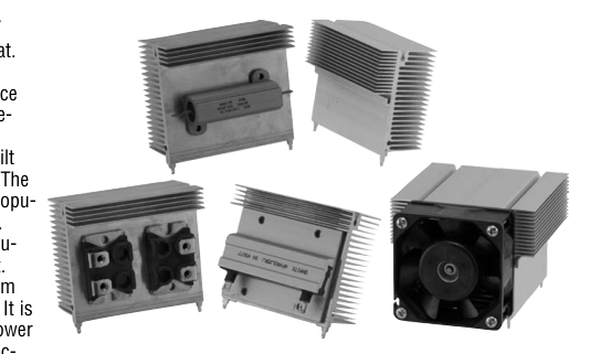
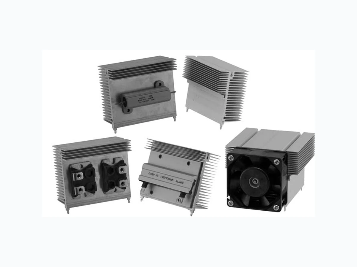
Ohmite introduces the powerful B60/
C60 series heatsink with cam clip (Pat.
Pending) or custom mounting. This
series offers flexible, high performance
and compact heat sink with exchange-
able cam clip system for TO-220,
TO-247, and TO-264 devices. The built
in lip is provided for mounting ease. The
optional B series can be tapped for popu-
lar Ohmite resistors or other devices.
These powerful heat sinks can be thru-
hole soldered as a single or dual unit.
The dual unit can be mated to a 60mm
fan for greater thermal performance. It is
the ideal type of heat sink for high power
density and small size (3U or 4U) elec-
tronic packaging with forced convection.
S E R I E S S P E C I F I C AT I O N S
Weight Length L
Heatsink
Surface Area (in2 / mm2)
Part Number
(oz / g)
C60-075-VE
177 / 114,300 5.7 / 163
C60-075-AE B60-075-VE
177 / 114,300 5.7 / 163
B60-075-AE
c h a r a c t e r i s t i c s
Heat Sink Aluminum Alloy 6063-T5 or Equivalent with either degreased or black anodized finish.
Spring Clip Music Wire, Per ASTM A228 with bright nickel plating
Cold-rolled Steel, Per ASTM A-366 with pure tin over copper strike.
Solder Foot
RoHS compliant.
Fan 60mm fan with 4 self-tapping M3 screws
Interface Thermal For improvement, use thermal joint compound, 0.005 Grafoil (TGon Resistance 800 by Laird), or phase change material (Hi-Flow by Bergquist) Insulator (Optional) Sil-Pad 900-S, K6 800-S and K10 by Bergquist
1-866-9-OHMITE • Int’l 1-847-258-0300 • Fax 1-847-574-7522 • www.ohmite.com • info@ohmite.com
(mm) consult factory for alternate lengths and 75 clip combinations
75
Heat Dissipation
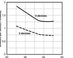
Fan Flow Rate (cfm)
(continued)
Page 2
B60/C60 Series
Heat Sink System
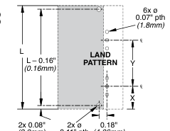
d i m e n s i o n s
2.58"
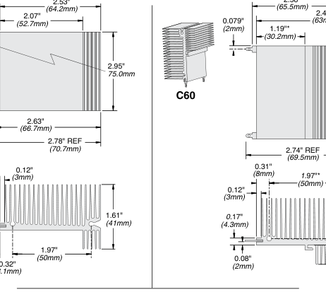
2x 0.079"
2.48"
(2mm)
(63mm)
2.79" (71.0mm)
2.95"
B60
(75.0mm)
0.049" (1.25mm)
0.17"
1.61
(4.3mm)
(41mm)
0.080" (2.03mm)
0.47" (12mm)
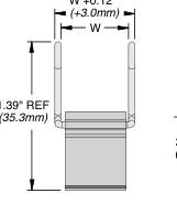
"W" T247 0.63" (16.1mm)
Clip Dimensions
T264 0.80" (20.2mm)
0.43"
W +0.12"
NOTE: Due to pos-
(11mm)
sible screw torquing
on long extrusions,
Customer should
check for coplanarity
0.78" (19.8mm)
prior to final assem-
bly or soldering.
(2.0mm) 0.11" pth (4.06mm) (2.8mm)
h o w t o o r d e r
Heatsink
RoHS compliant
C 6 0 X X - 0 5 8 - A E
Length Finish
Series Hole pattern (mm)
A = black anodized
B = without lip (optional)
V = degreased
C = with lip
Clip
C L A - T 2 4 7 - 2 1 E
Standard
Clip series Device type
RoHS
T247 = TO-247 configuration compliant T264 = TO-264
1-866-9-OHMITE • Int’l 1-847-258-0300 • Fax 1-847-574-7522 • www.ohmite.com • info@ohmite.com