
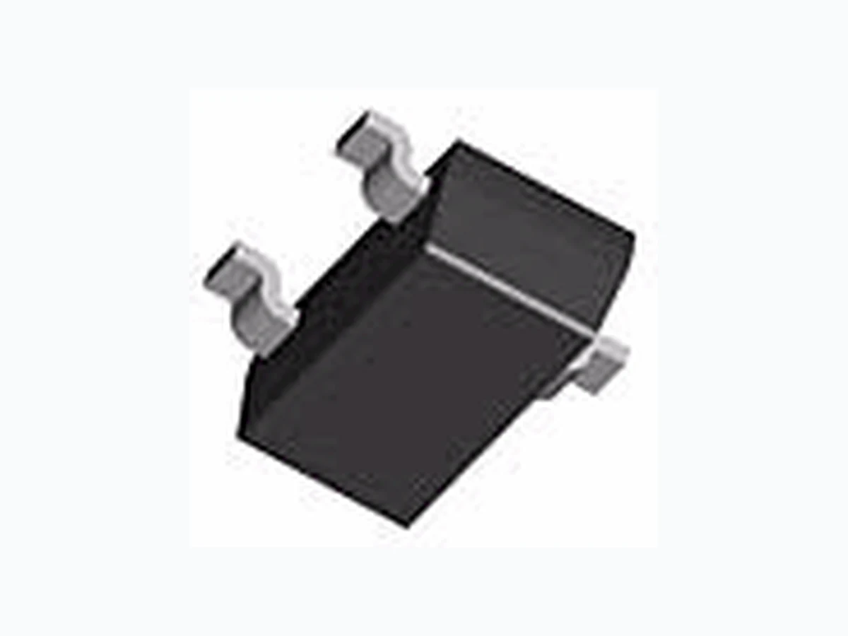
B431L ETC1
Document overview
- Manufacturer or author: Provided By www.digicamel.com(FREE DATASHEET DOWNLOAD SITE)
- PDF pages: 8
Technical content
Features
- Low voltage operation (down to 1.24V)
- Wide operating current……80µA to 100mA
- Trimmed bandgap design………….. ± 0.5%
- Wide temperature range…... -40 °°°°C to +85°°°°C
- Available in ….….SOT-23-3, TO-92 , 8SOIC
- Pin-to-Pin Replacement …………….SC431L
Applications
- Switching Power Supplies
- Adjustable Power Supplies
- Linear Regulators
- Battery Powered Equipment
- Monitors, TV, VCR
- Instrumentation SOT-23-3 (K3) Top View BAY Cathode Anode Ref Bottom View TO-92 (Z) 13 2 Ref Anode Cathode SOT-23-3 (K3) Top View BAY Cathode Anode Ref Bottom View TO-92 (Z) 13 2 Ref Anode Cathode Bay LinearBay LinearBay LinearBay Linear Inspire the Linear PowerInspire the Linear PowerInspire the Linear PowerInspire the Linear Power
Bay Linear, Inc 2418 Armstrong Street, Livermore, CA 94550 Tel: (925) 606-5950, Fax: (925) 940-9556 www.baylinear.com B431L Absolute Maximum Rating Recommended Operating Conditions Min Max Symbol Cathode Voltage, Vz V REF 16 V Cathode Current, Iz 80µA 100 mA
Electrical Characteristics
Unless specified: T٨25°C. Values in bold apply over full operating ambient temperature. B431LA 0.5% Parameter Symbol Condition Min Typ Max Units 1.234 1.246 Reference Voltage V REF V Z = VREF1 IZ = 10mA(1) 1.222 1.240 1.258 V VREF Temp Deviation VDEV V Z = VREF1, IZ = 10mA(1) IA=full range 10 25 mV Ratio of Change in VREF To Change in VZ Δ VREF ΔVZ IZ = 10mA,ΔVZ = 16V to VRef (2) -2.7 -1.0 mV/V Reference Input Current IREF R1 = 10kΩ , R2 = ∞ , IZ = 10mA(2) 0.15 0.5 µA IREF Temperature Deviation IREF(DEV) R1 = 10kΩ , R2 = ∞ , IZ = 10mA(2) 0.1 0.4 µA VREF = 0V, VZ =16V(3) 0.125 0.150 Off-State Cathode Current IZ (OFF) VREF = 0V, VZ =16V(3) 0.135 0.150 µA Min Operating Current IZ(MIN) V Z = VREF (1) 20 80 µA Dynamic Impedance Z KA VKA=Vref, IK=100µA to 100mA, f≤1kHA 0.05 0.15 Ω Parameter Symbol Maximum Units Cathode Voltage V z 20 V Continuous Cathode Current I z 100 mA Reference Input Current Range 3 mA Power Dissipation at TA - 25°C SOT-23-3 S0-8 TO-92 P D 0.37 0.75 0.95 W Thermal Resistance SOT-23-3 S0-8 TO-92 O JA 336 175 132 °C/W Operating Junction Temperature Range T J -40 to +150 °C Storage Temperature Range T STG -65 to +150 °C Lead Temperature (Soldering) 10 seconds T LEAD 300 °C ESD Rating (Human Body Model) T ESD 2 kV
Bay Linear, Inc 2418 Armstrong Street, Livermore, CA 94550 Tel: (925) 606-5950, Fax: (925) 940-9556 www.baylinear.com B431L Unless specified: T٨25°C. Values in bold apply over full operating ambient temperature. B431LB 1% Parameter Symbol Condition Min Typ Max Units 1.228 1.252 Reference Voltage V REF V Z = VREF1 IZ = 10mA(1) 1.215 1.240 1.265 V VREF Temp Deviation VDEV V Z = VREF1, IZ = 10mA(1) IA=full range 10 25 mV Ratio of Change in VREF To Change in VZ Δ VREF ΔVZ IZ = 10mA,ΔVZ = 16V to VRef (2) -1.0 -2.7 mV/V Reference Input Current IREF R1 = 10kΩ , R2 = ∞ , IZ = 10mA(2) 0.15 0.5 µA IREF Temperature Deviation IREF(DEV) R1 = 10kΩ , R2 = ∞ , IZ = 10mA(2) 0.1 0.4 µA VREF = 0V, VZ =16V(3) 0.125 0.150 Off-State Cathode Current IZ (OFF) VREF = 0V, VZ =16V(3) 0.135 0.150 µA Min Operating Current I Z(MIN) V Z = VREF (1) 20 80 µA Dynamic Impedance Z KA VKA=Vref, IK=100µA to 100mA, f≤1kHA 0.05 0.15 Ω Unless specified: T٨25°C. Values in bold apply over full operating ambient temperature. B431LC 2% Parameter Symbol Condition Min Typ Max Units 1.215 1.265 Reference Voltage V REF V Z = VREF1 IZ = 10mA(1) 1.200 1.240 1.280 V VREF Temp Deviation VDEV V Z = VREF1, IZ = 10mA(1) IA=full range 10 35 mV Ratio of Change in VREF To Change in VZ Δ VREF ΔVZ IZ = 10mA,ΔVZ = 16V to VRef (2) -1.0 -2.7 mV/V Reference Input Current IREF R1 = 10kΩ , R2 = ∞ , IZ = 10mA(2) 0.15 0.5 µA IREF Temperature Deviation IREF(DEV) R1 = 10kΩ , R2 = ∞ , IZ = 10mA(2) 0.1 0.4 µA VREF = 0V, VZ =16V(3) 0.125 0.150 Off-State Cathode Current IZ (OFF) VREF = 0V, VZ =16V(3) 0.135 0.150 µA Min Operating Current IZ(MIN) V Z = VREF (1) 20 80 µA Dynamic Impedance Z KA VKA=Vref, IK=100µA to 100mA, f≤1kHA 0.05 0.15 Ω
Bay Linear, Inc 2418 Armstrong Street, Livermore, CA 94550 Tel: (925) 606-5950, Fax: (925) 940-9556 www.baylinear.com B431L
Bay Linear, Inc 2418 Armstrong Street, Livermore, CA 94550 Tel: (925) 606-5950, Fax: (925) 940-9556 www.baylinear.com B431L Test Circuit: Small-Signal Gain & Phase Test Circuit: Stability 431 L
Bay Linear, Inc 2418 Armstrong Street, Livermore, CA 94550 Tel: (925) 606-5950, Fax: (925) 940-9556 www.baylinear.com B431L Application Notes: Stability: Selection of Load Capacitor Selection of load capacitor for when B431L is used as a shunt regulator, two options for selection of C L 1) No load capacitance across the device, decouple at the load 2) Large capacitance across the device, optional decoupling at the load. The reason for this is that B431L exhibits instability with capacitances in the range of 10nF to 1µF (approx.) at light cathode currents (up to 3mA typical). The device is less stable the lower the cathode voltage has been set for. Therefore while the device will be perfectly stable operating at a cathode current of 10mA with a 0.1µF capacitor across it, it will oscillate transiently during start-up as the cathode current passes through the instability region. Selecting a very low (or preferably, no) capacitance, or alternatively a high capacitance such as 10µF will avoid this issue altogether. Since the user anyway, the most cost effective method is to use no capacitance at all directly across the device. PCB trace/via resistance and inductance prevent the local load decoupling from causing the oscillation during the transient start-up phase. Note: if the B431L is located right at the load, so the load decoupling capacitor is directly across it, then this capacitor will have to be ≤1nF or ≥ 10µF B431
Bay Linear, Inc 2418 Armstrong Street, Livermore, CA 94550 Tel: (925) 606-5950, Fax: (925) 940-9556 www.baylinear.com B431L INTEL I 740 +3.3V 470µF0.1µF PHD 3055E 2.7V +12V 0.1µF B431L 120Ω 140Ω 500Ω 0.1µF 1000µF 0.1µF *If the output voltage has noise, then please add a 0.1µF in between drain and gate of power MOSFET to reduce the noise. Application Circuit: Test Circuits:
Bay Linear, Inc 2418 Armstrong Street, Livermore, CA 94550 Tel: (925) 606-5950, Fax: (925) 940-9556 www.baylinear.com B431L SOT-23 Advance Information- These data sheets contain descriptions of products that are in development. The specifications are based on the engineering ca lculations, computer simulations and/ or initial prototype evaluation. Preliminary Information- These data sheets contain minimum and maximum specifications that are based on the initial device characterizations. These lim its are subject to change upon the completion of the full characterization over the specified temperature and supply voltage ranges. The application circuit examples are only to explain the representative applications of the devices and are not intended to gua rantee any circuit design or permit any industrial property right to other rights to execute. Bay Linear takes no responsibility for any problems related to any industrial property right resulting from the use of the contents shown in the data book. Typical parameters can and do vary in different applications. Customer’s technical experts must validate all operating parameters including “ Typical” for each customer application. LIFE SUPPORT AND NUCLEAR POLICY Bay Linear products are not authorized for and should not be used within life support systems which are intended for surgical implants into the body to support or sustain life, in aircraft, space equipment, submarine, or nuclear facility applications without the specific written consent of Bay Linear President. 0.015 - 0.018 (0.381 - 0.457) 0.020 - 0.024 (0.508 - 0.610) 0.110 - 0.120 (2.794 - 3.048) 0.001 - 0.004 (0.025 - 0.102) 0.030 - 0.041 (0.762 - 1.041) 0.018 - 0.024 (0.457 - 0.610) 0.070 - 0.080 (1.778 - 2.032) 0.035 - 0.040 (0.889 - 1.016) 0.047 - 0.055 (1.194 - 1.397) 0.083 - 0.098 (2.108 - 2.489) 0.003 - 0.005 (0.076 - 0.127)