
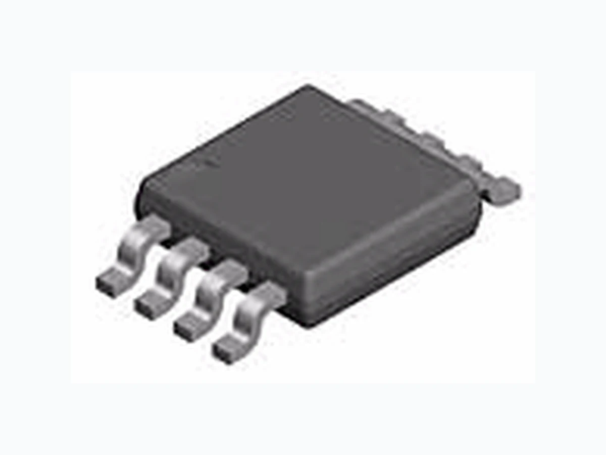
B431 ETC1
Document overview
- Manufacturer or author: Provided By www.digicamel.com(FREE DATASHEET DOWNLOAD SITE)
- PDF pages: 11
Technical content
Features
- Wide Operating Range …1mA to100mA
- Tight Band Gap Tolerance …….… 0.5%
- Low Temp. Coefficient………..30 ppm/ oC
- Wide temp range of –40 to +105oC
- Available in TO92, SOT-89, SO-8
Applications
- Switching Power Supplies
- Adjustable Power Supplies
- Linear Regulators
- Battery Powered Equipment
- Monitors, TV, VCR
- Instrumentation Bay Linear Inspire the Linear Power
Bay Linear, Inc 2418 Armstrong Street, Livermore, CA 94506 Tel: (925) 606-5950, Fax: (925) 940-9556 www.baylinear.com B431 Absolute Max Ratings Recommended Operating Conditions Min Max Symbol Cathode Voltage, Vz V REF 36 V Cathode Current, Iz 0.1 100 mA
Electrical Characteristics
Unless specified: T٨25°C. Values in bold apply over full operating ambient temperature. B431 0.5% Parameter Symbol Condition Min Typ Max Units Reference Voltage V REF V Z = VREF1 IZ = 10mA(1) 2.483 2.495 2.507 V VREF Temp Deviation V DEV V Z = VREF1 IZ = 10mA(1) 4 17 mV IZ = 10mA,∆VZ = 10V to VRef -1.0 -2.7 Ratio of Change in VREF To Change in VZ ∆ VREF ∆VZ IZ = 10mA,∆VZ = 36V to 10V -0.4 -2.0 mV/V Reference Input Current IREF R1 = 10kΩ, R2 = ∞, IZ = 10mA(2) 0.7 4 µA IREF Temperature Deviation IREF(DEV) R1 = 10kΩ, R2 = ∞, IZ = 10mA(2) 0.4 1.2 µA Off-State Cathode Current IZ (OFF) V REF = 0V, VZ =36V(3) 0.1 1 µA Dynamic Output Impedance rz F <1kHz, VZ = VREF IZ = 1mA to 100mA(1) 0.20 0.50 Ω Minimum Operating Current IZ(MIN) V Z = VREF (1) 0.4 1 mA Parameter Symbol Maximum Units Cathode Voltage V z 37 V Continuous Cathode Current I z 150 mA Reference Input Current I REF 10 mA Power Dissipation at TA - 25°C SOT-89 S0-8 TO-92 PD 1000 750 775 mW Thermal Resistance S0-8 TO-92 SOT-89 OJA 175 160 110 °C/W Operating Junction Temperature Range T J -40 to +150 °C Operating Ambient Temperature T A -40 to +105 °C Storage Temperature Range T STG -65 to +150 °C Lead Temperature (Soldering) 10 seconds T LEAD 300 °C ESD Rating (Human Body Model) T ESD 2 kV
Bay Linear, Inc 2418 Armstrong Street, Livermore, CA 94506 Tel: (925) 606-5950, Fax: (925) 940-9556 www.baylinear.com B431 B431 1% Parameter Symbol Condition Min Typ Max Units Reference Voltage V REF V Z = VREF1 IZ = 10mA(1) 2.470 2.495 2.520 V VREF Temp Deviation V DEV V Z = VREF1 IZ = 10mA(1) 4 17 mV IZ = 10mA,∆VZ = 10V to VRef -1.0 -2.7 Ratio of Change in VREF To Change in VZ ∆ VREF ∆VZ IZ = 10mA,∆VZ = 36V to 10V -0.4 -2.0 mV/V Reference Input Current IREF R1 = 10kΩ, R2 = ∞, IZ = 10mA(2) 0.7 4 µA IREF Temperature Deviation IREF(DEV) R1 = 10kΩ, R2 = ∞, IZ = 10mA(2) 0.4 1.2 µA Off-State Cathode Current IZ (OFF) V REF = 0V, VZ =36V(3) 0.1 1 µA Dynamic Output Impedance rz F <1kHz, VZ = VREF IZ = 1mA to 100mA(1) 0.20 0.50 Ω Minimum Operating Current IZ(MIN) V Z = VREF (1) 0.4 1 mA B431 2% Parameter Symbol Condition Min Typ Max Units Reference Voltage V REF V Z = VREF1 IZ = 10mA(1) 2.445 2.495 2.545 V VREF Temp Deviation V DEV V Z = VREF1 IZ = 10mA(1) 4 17 mV IZ = 10mA,∆VZ = 10V to VRef -1.0 -2.7 Ratio of Change in VREF To Change in VZ ∆ VREF ∆VZ IZ = 10mA,∆VZ = 36V to 10V -0.4 -2.0 mV/V Reference Input Current IREF R1 = 10kΩ, R2 = ∞, IZ = 10mA(2) 0.7 4 µA IREF Temperature Deviation IREF(DEV) R1 = 10kΩ, R2 = ∞, IZ = 10mA(2) 0.4 1.2 µA Off-State Cathode Current IZ (OFF) V REF = 0V, VZ =36V(3) 0.1 1 µA Dynamic Output Impedance rz F <1kHz, VZ = VREF IZ = 1mA to 100mA(1) 0.20 0.50 Ω Minimum Operating Current IZ(MIN) V Z = VREF (1) 0.4 1 mA
Bay Linear, Inc 2418 Armstrong Street, Livermore, CA 94506 Tel: (925) 606-5950, Fax: (925) 940-9556 www.baylinear.com B431 B431D 1% Parameter Symbol Condition Min Typ Max Units Reference Voltage V REF V Z = VREF1 IZ = 10mA(1) 2.470 2.495 2.520 V VREF Temp Deviation V DEV V Z = VREF1 IZ = 10mA(1) 4 17 mV IZ = 10mA,∆VZ = 10V to VRef -1.0 -2.7 Ratio of Change in VREF To Change in VZ ∆ VREF ∆VZ IZ = 10mA,∆VZ = 36V to 10V -0.4 -2.0 mV/V Reference Input Current IREF R1 = 10kΩ, R2 = ∞, IZ = 10mA(2) 0.7 4 µA IREF Temperature Deviation IREF(DEV) R1 = 10kΩ, R2 = ∞, IZ = 10mA(2) 0.4 1.2 µA Off-State Cathode Current IZ (OFF) V REF = 0V, VZ =36V(3) 0.1 1 µA Dynamic Output Impedance rz F <1kHz, VZ = VREF IZ = 1mA to 100mA(1) 0.20 0.50 Ω Minimum Operating Current IZ(MIN) V Z = VREF (1) 0.4 1 mA Note 1: B431D is rated at -40°C to +85°C and 50ppm/°C
Bay Linear, Inc 2418 Armstrong Street, Livermore, CA 94506 Tel: (925) 606-5950, Fax: (925) 940-9556 www.baylinear.com B431 TO-92 0.055 (1.397) 0.045 (1.143) 0.145 (3.683) 0.135 (3.429) 10° typ. BOTTOM VIEW 0.185 (4.699) 0.045 (1.143) 0.185 (4.699) 0.175 (4.445) 0.085 (2.159) Diameter 0.090 (2.286) typ. Seating Plane 0.016 (0.406) 0.014 (0.356) 0.055 (1.397) 0.045 (1.143) 0.105 (2.667) 0.095 (2.413) 0.500 (12.70) Min. 0.025 (0.635) Max Uncontrolled Lead Diameter 5° typ. 5° typ. 0.090 (2.286) Radius typ. 0.0155 (0.3937) 0.0145 (0.3683)
Bay Linear, Inc 2418 Armstrong Street, Livermore, CA 94506 Tel: (925) 606-5950, Fax: (925) 940-9556 www.baylinear.com B431 SOT-89 Advance Information- These data sheets contain descriptions of products that are in development. The specifications are based on the engineering calculations, computer simulations and/ or initial prototype evaluation. Preliminary Information- These data sheets contain minimum and maximum specifications that are based on the initial device characterizations. These limits are subject to change upon the completion of the full characterization over the specified temperature and supply voltage ranges. The application circuit examples are only to explain the repres entative applications of the devices and are not intended to gua rantee any circuit design or permit any industrial property right to other rights to execute. Bay Linear takes no responsibility for any problems related to any industrial property right resulting from the use of the contents shown in the da ta book. Typical parameters can and do vary in different applications. Customer’s technical experts must validate all operating parameters including “ Typical” for each customer application. LIFE SUPPORT AND NUCLEAR POLICY Bay Linear products are not authorized for and should not be used within life support systems which are intended for surgical implants into the body to support or sustain life, in aircraft, space equipment, submarine, or nuclear facility applications without the specific written consent of Bay Linear President. A 1 2 3 P K F G D B STYLE 1 PIN 1. BASE 2. COLLECTOR 3. EMITTER STYLE 3 PIN 1. GATE 2. ANODE 3. CATHODE STYLE 2 PIN 1. ANODE 2. CATHODE 3. NO CONNECTION PIN 1. DRAIN 2. GATE 3. SOURCE STYLE 4 MILLIMETERS INCHESDIM MIN MAX MIN MAX A 4.40 4.60 0.174 0.181 B 2.29 2.60 0.091 0.102 C 140 160 0.056 0.062 D 0.36 0.48 0.015 0.018 E 1.62 1.80 0.064 0.070 F 0.44 0.53 0.018 0.020 G J 0.35 0.44 0.014 0.017 K 0.80 1.04 0.032 0.040 L 300 BSC 0.118 BSC N 2.04 2.28 0.081 0.089 P 3.94 4.25 0.156 0.167 150 BSC 0.059 BSC -T- N C J rr