
B3WN ETC
Document overview
- Manufacturer or author: Provided By www.digicamel.com(FREE DATASHEET DOWNLOAD SITE)
- PDF pages: 4
Technical content
/G01 Mechanical Key Switch B3WN Double-sealing Construction Assures Water-tight/Dust-tight Protection 8 x 8 mm compact size Allows the use of radial-taping part insertion machines Conforms to IEC529 IP67
Ordering Information
Size Height x pitch Operating force (OF) Part Number 8x8m m 13 x 5 mm 200 gf B3WN-6002 Note: Orders must be made in units of 1,000 pieces. /G01 CONSTRUCTION Pushbutton Case Rubber seal Film Plunger Disc spring Base Terminal
Switching capacity 50 mA, 12 VDC (resistive load) Insulation voltage 30 VDC Contact configuration SPST-NO Contact material Silver plating Contact resistance 100 mΩ max. (initial value) (rated: 1 mA, 5 VDC) Insulation resistance 100 MΩ min. (at 100 VDC) Dielectric strength 250 VAC, 50/60Hz for 1 min Bounce time 10 ms max. Vibration resistance Malfunction: 10 to 55 Hz, 1.5-mm double amplitude Shock resistance Destruction: 784 m/s2 min. {approx. 80G min.} Malfunction: 100 m/s2 min. {approx. 10G min.} Life expectancy 100,000 operations min. Ambient temperature Operating -- 2 5°Ct o8 5°C( - - 1 3°F to 185°F) with no icing Ambient humidity Operating 35% to 85% Weight Approx. 0.7 g /G01 CHARACTERISTIC DATA Stroke S (mm) Operating force (gf) /G01 OPERATING CHARACTERISTICS B3WN-6002 Operating force (OF) 200±70 gf Releasing force (RF) 50 gf min. Pretravel (PT) 0.3 mm +0.2 -- 0 . 1
Unit: mm (inch) Fixed tape Master tape Recommended mounting holes and internal connection (PCB thickness t=1.6 mm) 3.8 (0.15) dia. 4±0.3 dia. (0.16±0.01 dia.) B3WN-6002 PCB Pad (Top View) (One-side PCB t=1.6) Terminal Arrangement/ Internal Connection (Top View) Two, 1+0.1 dia. 8±0.2 (0.31±0.008) 13±0.2 (0.51±0.008) 8±0.2 (0.31±0.008) (0.35) 5±0.1 (0.20±0.004) 5±0.2 (0.20±0.008) 0.6 (0.02) 0.9 (0.04) 0.3 (0.01) 0.2 (0.008) max. 0.2 (0.008) max. 0.9 (0.04) 0.6 (0.02) 12.7±1.0 (0.25±0.04) 3.85±0.5 (0.15±0.02) 12.7±0.3 (0.50±0.01) 12.7±0.3 (0.50±0.01) 0.5 (0.02) max. 18+1 (0.71+0.04) 18+1 (0.71+0.04) -- 0 . 5 - -0.02 Note: 1. In accordance with EIAJ RC-1008, unless otherwise specified. 2. Switch fixing direction (A and B) on the tape may change. Precautions /G01 OPERATION Do not repeatedly operate the Switch with high force, apply additional force to the pushbutton once it has stopped moving, or operate the Switch with excessive force, otherwise the disc spring of the Switch may deform and the Switch may malfunction. Be sure to set the Switch so that the pushbutton will be pressed straight. A decrease in the life of the Switch may result if the pushbutton is pressed off-center or from an acute angle. /G01 PCB The Switch is designed for a 1.6-mm-thick, single-sided PCB as a standard PCB. The Switch may not be mounted to any other type of PCB, such as a double-sided, through-hole PCB, or any other one that is different in thickness. Furthermore, the Switch may not operate properly or withstand the soldering heat if it is mounted to such a PCB. Be sure to test the PCB before use. /G01 SOLDERING The Switch can be soldered automatically or manually. The automatic soldering of the Switch on a 1.6-mm-thick, single-sided PCB must be completed within five seconds at a soldering temperature of 260°C maximum. The manual soldering of the Switch on a 1.6-mm-thick, single-sided PCB must be completed within three seconds at a soldering iron tip temperature of 350°C maximum. When using a multi-layer PCB, test the PCB in advance because the Switch mounted to the PCB may be deformed by heat if the pattern or land design is improper. Soldering may be repeated only once at a minimum interval of five minutes if the Switch is not soldered properly. Make sure that no flux will rise on the mounting surface of the PCB.
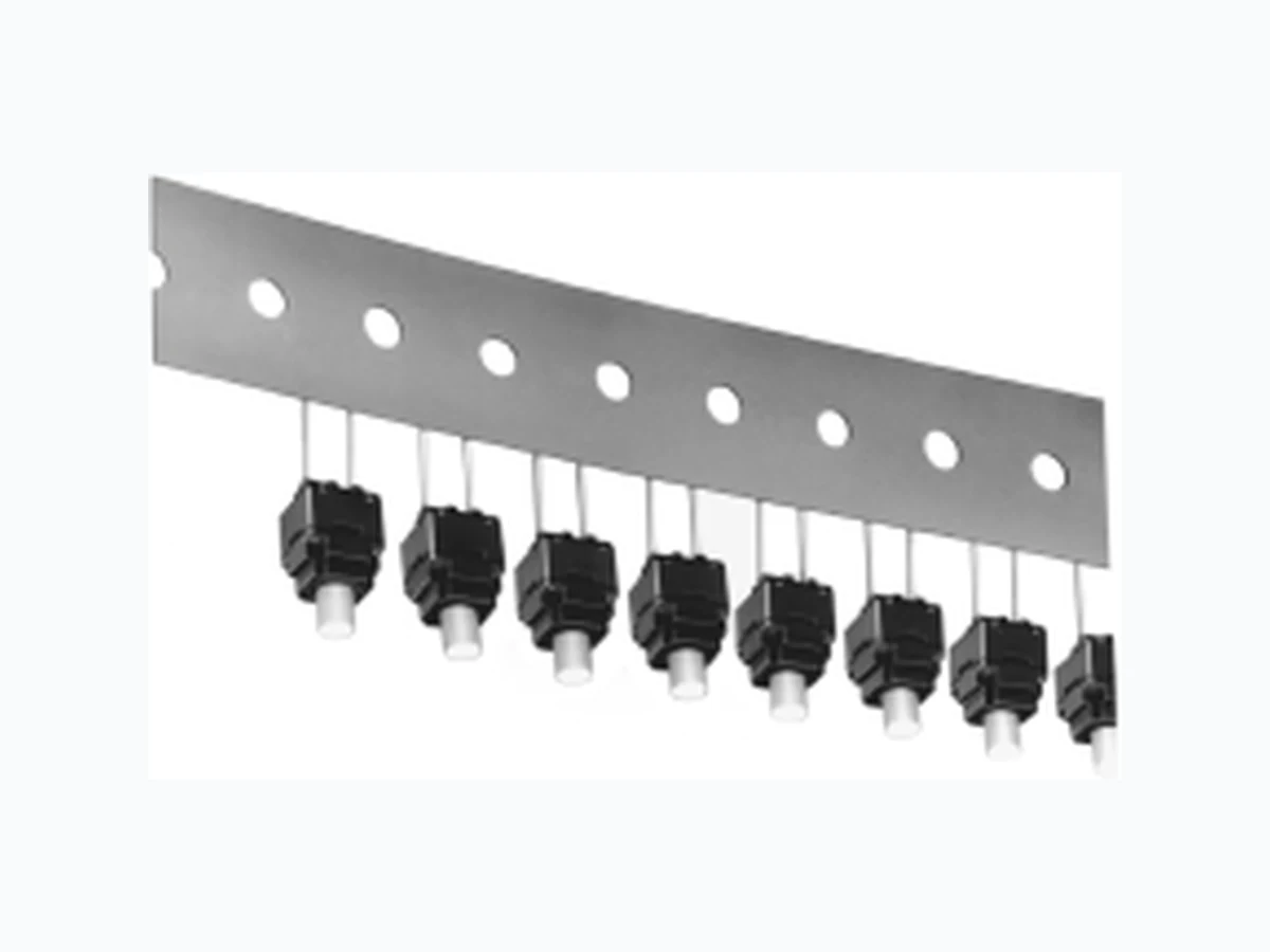
/G01 PACKAGE B3W N Switches are packed on tape as show n below. B3W N Switches on tape Package Stored zigzag 350 326 D o notpress strongly,vibrate,ordrop the package,otherwise the terminals ofthe Switches ma y deform. Pulloutthe tape slowly.Ma ke sure thatthe tape is notentangled while pulling itout,otherwise the terminals ofthe Switches may deform. D o notstore the package in locations with high temperature or high humidity.U se the Switches as soon as possible.The package mad e ofpaperis nottightly sealed.Storing the package in locations with high temperature orhigh humidity fora long time ma y resultin the discoloration ofthe Switch terminals. /G01 OTHE R PRECAUTIONS Whe n using the Switch ina very humid environmentorwhere condensation ma y occur:moun tswitch first,then completely coverthe terminals with coating in orderto preventcurrent leakage from terminals. D o notuse coating materials thatcontain toluene orxylene. NOTE :DIMENSION S SHOW N AR E IN MILLIMETERS .To convertmillimeters to inches divide by 25.4. /G01