

 Download PDF
B3DQ3BRG-05C0001L3U1930 HARVATEK
Document overview
- PDF pages: 15
Technical content
Page 1
Harvatek Surface Mount CHIP LEDs Data Sheet
Features
Support control circuit to be integrated with RGB chips into a single package
Support signal reshaping to pass control waveforms to next adjacent driver
Cascading port transmission by a single data line
Support bi-directional data transfer protocol to feedback LED strip information, including quantity of the cascaded LDE devices and the maximal sink current capability of driver chip (patented)
Support parallel-connected multi-strip control mechanism (patented)
Support sleep mode for power saving (patented)
Optional maximal driving current: 5mA
256-step gray-scale output to allow 16,777,216-color display
Support 20Khz (maximum) PWM refresh rate
Support 32-level dimming control for R/G/B channel.
Built-in oscillator with 20MHz frequency
LED driver port maximum withstand Voltage 6.5V
Built-in power-on-reset
Built-in Brown-out reset
Operating voltage 3.3~5.5V
Applications
Decorative LED lighting
LED video display

| Official Product | HT Part No. B3DQ3BRG-05C0001L3U1930 | |||
|---|---|---|---|---|
| Tentative Product | **************** | **************** | ||
| Specifications are subject to changes for improvement without advance notice. Proprietary data, drawings, company confidential all rights reserved. | 04/14/2022 | Version 1.0 | Page 1/15 | |
Page 2
DISCLAIMER ......................................................................................................................................... 3 LIFE SUPPORT POLICY ............................................................................................................. 3
PRODUCT SPECIFICATIONS ............................................................................................................. 4
ATTENTION: ELECTROSTATIC DISCHARGE (ESD) PROTECTION ............................................... 4
LABEL SPECIFICATIONS ................................................................................................................... 5
SPECIFICATIONS RANGE .................................................................................................................. 6
PRODUCT FEATURES ......................................................................................................................... 7
ELECTRO-OPTICAL CHARACTERISTICS ...................................................................................... 7 PACKAGE OUTLINE DIMENSION AND RECOMMENDED SOLDERING PATTERN FOR REFLOW
SOLDERING ............................................................................................................................. 7
ELECTRICAL CHARACTERISTICS ................................................................................................. 8 DATA TRANSFER PROTOCOL ..................................................................................................................... 9
PRECAUTION FOR USE .................................................................................................................... 10
PACKAGING .........................................................................................................................................11 TAPE DIMENSION ................................................................................................................... 11 REEL DIMENSION ................................................................................................................... 12 PACKING ............................................................................................................................... 12 DRY PACK ............................................................................................................................ 13
BAKING................................................................................................................................. 13 PRECAUTIONS ....................................................................................................................... 13
REFLOW SOLDERING ...................................................................................................................... 14 REWORKING .......................................................................................................................... 14 CLEANING ............................................................................................................................. 14 CAUTIONS OF PICK AND PLACE .............................................................................................. 15 REVISE HISTORY ................................................................................................................... 15
| Official Product | HT Part No. B3DQ3BRG-05C0001L3U1930 | |||
|---|---|---|---|---|
| Tentative Product | **************** | **************** | ||
| Specifications are subject to changes for improvement without advance notice. Proprietary data, drawings, company confidential all rights reserved. | 04/14/2022 | Version 1.0 | Page 2/15 | |
Page 3
DISCLAIMER
HARVATEK reserves the right to make changes without further notice to any products herein to improve reliability, function or design. HARVATEK does not assume any liability arising out of the application or use of any product or circuit described herein; neither does it convey any license under its patent rights, nor the rights of others.
Life Support Policy HARVATEK’s products are not authorized for use as critical components in life support devices or systems without the express written approval of the President of HARVATEK or HARVATEK INTERNATIONAL. As used herein: 1. Life support devices or systems are devices or systems which, (a) are intended for surgical implant into the body, or (b) support or sustain life, and (c) whose failure to perform when properly used in accordance with instructions for use provided in the labeling, can be reasonably expected to result in a significant injury of the user. 2. A critical component in any component of a life support device or system whose failure to
perform can be reasonably expected to cause the failure of the life support device or system, or to affect its safety or effectiveness.
| Official Product | HT Part No. B3DQ3BRG-05C0001L3U1930 | |||
|---|---|---|---|---|
| Tentative Product | **************** | **************** | ||
| Specifications are subject to changes for improvement without advance notice. Proprietary data, drawings, company confidential all rights reserved. | 04/14/2022 | Version 1.0 | Page 3/15 | |
Page 4
Product Specifications
| Item | Specification | Material | Quantity |
| Luminous Intensity(Iv) | Red : 40~120 mcd Green : 60~180 mcd Blue : 15~60 mcd IC@5V, R/G/B@5mA Ts= 25O C; Tolerance ±10% | ||
| Wavelength | Red : 618~630 nm Green : 518~535 nm Blue : 460~474 nm IC@5V, R/G/B@5mA Ts= 25O C; Tolerance ±10% | ||
| Applied voltage | 5V_DC | ||
| View angle | 120o | ||
| Resin | Clear | Epoxy | |
| Carrier tape | Conductive black tape | 3000 ea/reel | |
| Reel | Conductive black | ||
| Label | HT standard | Paper | |
| Packing bag | 250x230mm | Aluminum laminated bag/ no-zipper | One reel per bag |
| Carton | HT standard | Paper | Non-specified |
| Others: Each immediate box consists of 5 reels. The 5 reels may not necessarily have the same lot number or the same bin combinations of Iv, λ and Vf. Each reel has a label identifying its specification; the immediate box consists of a product label D as well. Note :This is shipped test conditions ※Remarks: This product should be operated in forward bias. If a reverse voltage is continuously applied to the product, such operation can cause migration resulting in LED damage. ATTENTION: Electrostatic Discharge (ESD) protection The symbol to the left denotes that ESD precaution is needed. ESD protection for GaP and AlGaAs based chips is necessary even though they are relatively safe in the presence of low static-electric discharge. Parts built with AlGaInP, GaN, or/and InGaN based chips are STATIC SENSITIVE devices. ESD precaution must be taken during design and assembly. If manual work or processing is needed, please ensure the device is adequately protected from ESD during the process. | |||
| Official Product | HT Part No. B3DQ3BRG-05C0001L3U1930 | |||
|---|---|---|---|---|
| Tentative Product | **************** | **************** | ||
| Specifications are subject to changes for improvement without advance notice. Proprietary data, drawings, company confidential all rights reserved. | 04/14/2022 | Version 1.0 | Page 4/15 | |
Page 5
Label Specifications
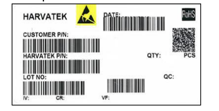
■Harvatek P/N:
B
3DQ
3 BRG-
05C 0001
L3
| Product | Package | Dice Qty | Color | Current | Series Number | Taping |
| PCB | 3.2(L)x1.5(W)x1.0(H) mm | 3:Tri | BRG(Full Color) | 5mA | X001~XZZZ | 1.Taping style 2. Qty |
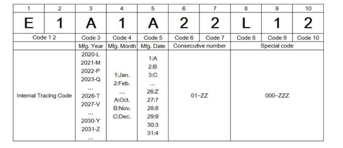
■ Lot No.:
| Official Product | HT Part No. B3DQ3BRG-05C0001L3U1930 | |||
|---|---|---|---|---|
| Tentative Product | **************** | **************** | ||
| Specifications are subject to changes for improvement without advance notice. Proprietary data, drawings, company confidential all rights reserved. | 04/14/2022 | Version 1.0 | Page 5/15 | |
Page 6
Specifications Range ■Luminous Intensity (Iv) :
| Color | Spec. Range |
| R | 40-120 mcd |
| G | 60-180 mcd |
| B | 15-60 mcd |
Note: It maintains a tolerance of ±10% on luminous intensity
■Wavelength :
| Color | Spec. Range |
| R | 618-630 nm |
| G | 518-535 nm |
| B | 460-474 nm |
Note: It maintains a tolerance of + 0.5nm on Wavelength Bin
| Official Product | HT Part No. B3DQ3BRG-05C0001L3U1930 | |||
|---|---|---|---|---|
| Tentative Product | **************** | **************** | ||
| Specifications are subject to changes for improvement without advance notice. Proprietary data, drawings, company confidential all rights reserved. | 04/14/2022 | Version 1.0 | Page 6/15 | |
Page 7
Product Features Electro-Optical Characteristics
(TSoldering , 25 oC)
| Series | Emitting Color | Material | Wavelength λ(nm) | I (mcd) V | Viewing Angle 21 2 | ||
| λ D | λ P | △λ | Typical | ||||
| B3DQ3BRG | R | AllnGaP | 624 | 630 | 18 | 65 | 120 |
| G | InGaN | 523 | 518 | 35 | 85 | 120 | |
| B | InGaN | 468 | 465 | 25 | 20 | 120 | |
Package Outline Dimension and Recommended Soldering Pattern for Reflow Soldering
(Unit:mm Tolerance: +/-0.1)
| Outline Dim. | Soldering Pattern |
| Soldering terminals may shift in the x, y direction. | |
Absolute Maximum Ratings (unless otherwise specified, Temperature=25°C)
( TSoldering 25 ℃)
| Characteristic | Symbol | Rating | Unit |
|---|---|---|---|
| Supply Voltage | VDD | 6.5 | V |
| Power Dissipation | PD | <300 | mW |
| Maximum Output Current | ILEDOUT | 25 | mA |
| Welding Temperature | TM | 300(8S) | °C |
| Operating Temperature Range | TOPR | -25~85 | °C |
| Storage Temperature Range | TSTO | -65~120 | °C |
| Official Product | HT Part No. B3DQ3BRG-05C0001L3U1930 | |||
|---|---|---|---|---|
| Tentative Product | **************** | **************** | ||
| Specifications are subject to changes for improvement without advance notice. Proprietary data, drawings, company confidential all rights reserved. | 04/14/2022 | Version 1.0 | Page 7/15 | |
Page 8
Electrical Characteristics
| Parameter | Symbol | Min. | Typ. | Max. | Units | Note |
|---|---|---|---|---|---|---|
| Supply Voltage | VDD | 3.3 | 5 | 5.5 | V | |
| Sleep Current | I sleep | 5 | uA | |||
| Operation Current | I DD | 1.0 | 1.5 | mA | R, G, B no load | |
| Input High “H” of DI | V IH | 2.7 | VDD | V | ||
| Input Low “L” of DI | V IL | 0 | 1.0 | V | ||
| Pull Down Resistance | R PD | 500K | Ω | R , R IN out | ||
| Output High “H” of DO | V OH | 4.5 | V | I =4mA OH | ||
| Output Low “L” of DO | V OL | 0.4 | V | I =4mA OL | ||
| R, G, B Sink Current | I SINK | 4.75 | 5 | 5.25 | mA | VDD-Vf ≥1.2V LED |
| Input leakage | I leak | 1 | uA | D =0V IN | ||
| R, G, B off leakage current | I off | 1 | uA | PWM=0(off), @R, G, B =5V |
| Parameter | Symbol | Min. | Typ. | Max. | Units | Note |
|---|---|---|---|---|---|---|
| Propagation delay time | tPLZ | 80 | ns | D → D , CL=30pF IN OUT | ||
| tPZL | 80 | ns | ||||
| Rising time | tTHL | 15 | ns | |||
| Falling time | tTLH | 15 | ns | |||
| Rising time | tR | 50 | ns | R, G, B=12mA, CL=30pF | ||
| Falling time | tF | 50 | ns | |||
| Data rate | F data | 800 | Khz |
| Official Product | HT Part No. B3DQ3BRG-05C0001L3U1930 | |||
|---|---|---|---|---|
| Tentative Product | **************** | **************** | ||
| Specifications are subject to changes for improvement without advance notice. Proprietary data, drawings, company confidential all rights reserved. | 04/14/2022 | Version 1.0 | Page 8/15 | |
Page 9
Data Transfer Protocol
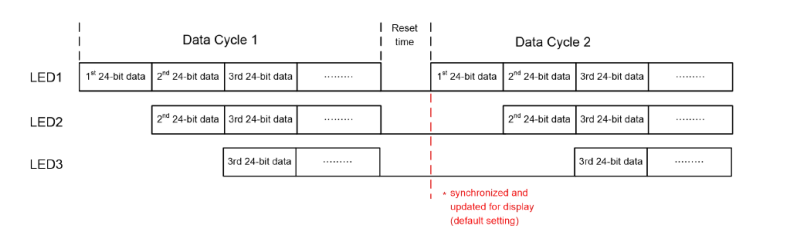
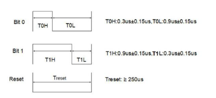
The single wire data transfer protocol supports 24-bit data for each LED RGB display data refresh. The IC receives 24-bit data and passes the remaining data to next LED. The 24-bit data consist of red, green and blue data, each with 8-bit width, and are transferred with MSB first.
The transferred data are recognized based on the pulse widths received by the IC. A low bit 0 is represented by a 0.3us high pulse followed by a 0.9us low pulse. A high bit 1 is represented by a 0.9us high pulse followed by a 0.3us low pulse. A low pulse ≧ 200us is used to issue a reset command to the IC to start a new cycle of serial commands.
| Official Product | HT Part No. B3DQ3BRG-05C0001L3U1930 | |||
|---|---|---|---|---|
| Tentative Product | **************** | **************** | ||
| Specifications are subject to changes for improvement without advance notice. Proprietary data, drawings, company confidential all rights reserved. | 04/14/2022 | Version 1.0 | Page 9/15 | |
Page 10
Precaution for Use 1. The chips should not be used directly in any type of fluid such as water, oil, organic solvent, etc. 2. When the LEDs are illuminating, the maximum ambient temperature should be first considered before operation. 3. LEDs must be stored in a clean environment. A sealed container with a nitrogen atmosphere is necessary if the storage period is over 3 month after shipping. 4. The LEDs must be used within 168 hours after unpacked. Unused products must be repacked in an anti-electrostatic package, folded to close any opening and then stored in a dry and cool space. 5. The appearance and specifications of the products may be modified for improvement
without further notice. 6. The LEDs are sensitive to the static electricity and surge. It is strongly recommended to use a grounded wrist band and anti-electrostatic glove when handling the LEDs. If a voltage over the absolute maximum rating is applied to LEDs, it will damage LEDs. Damaged LEDs will show some abnormal characteristics such as remarkable increase of leak current, lower turn-on voltage and getting unlit at low current.
| Official Product | HT Part No. B3DQ3BRG-05C0001L3U1930 | |||
|---|---|---|---|---|
| Tentative Product | **************** | **************** | ||
| Specifications are subject to changes for improvement without advance notice. Proprietary data, drawings, company confidential all rights reserved. | 04/14/2022 | Version 1.0 | Page 10/15 | |
Page 11
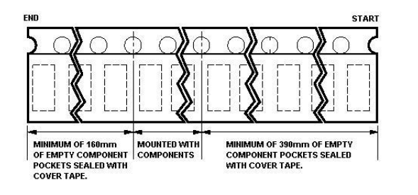
Packaging Tape Dimension
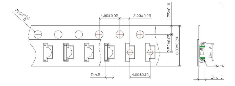
| Dim. A | Dim. B | Dim. C | Qty/Reel |
| 3.40±0.10 | 1.70±0.10 | 1.20±0.10 | 3K |
| Official Product | HT Part No. B3DQ3BRG-05C0001L3U1930 | |||
|---|---|---|---|---|
| Tentative Product | **************** | **************** | ||
| Specifications are subject to changes for improvement without advance notice. Proprietary data, drawings, company confidential all rights reserved. | 04/14/2022 | Version 1.0 | Page 11/15 | |
Page 12
Reel Dimension
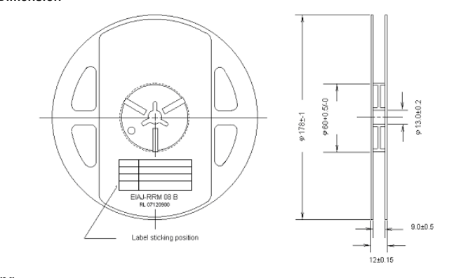
Packing
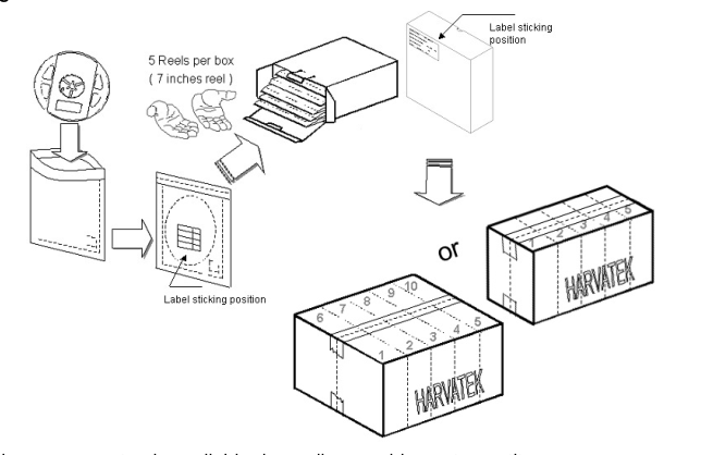
5 or 10 boxes per carton is available depending on shipment quantity.
| Official Product | HT Part No. B3DQ3BRG-05C0001L3U1930 | |||
|---|---|---|---|---|
| Tentative Product | **************** | **************** | ||
| Specifications are subject to changes for improvement without advance notice. Proprietary data, drawings, company confidential all rights reserved. | 04/14/2022 | Version 1.0 | Page 12/15 | |
Page 13
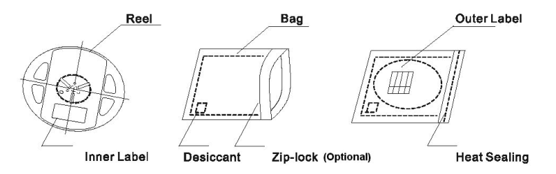
Dry Pack All SMD optical devices are MOISTURE SENSITIVE. Avoid exposure to moisture at all times during transportation or storage. Every reel is packaged in a moisture protected anti-static bag. Each bag is properly sealed prior to shipment.
A humidity indicator will be included in the moisture protected anti-static bag prior to shipment.
The packaging sequence is as follows:
Baking Baking before soldering is recommended when the package has been unsealed for 168 hours. The conditions are as followings: 1. 60±3℃×(12~24hrs)and<5%RH, taped reel type. 2. 100±3℃×(45min~1hr), bulk type. 3. 130±3℃×(15min~30min), bulk type. Precautions 1. Avoid exposure to moisture at all times during transportation or storage. 2. Anti-Static precaution must be taken when handling GaN, InGaN, and AlGaInP products. 3. It is suggested to connect the unit with a current limiting resistor of the proper size. Avoid applying a reverse voltage beyond the specified limit. 4. Avoid operation beyond the limits as specified by the absolute maximum ratings. 5. Avoid direct contact with the surface through which the LED emits light.
- If possible, assemble the unit in a clean room or dust-free environment.
| Official Product | HT Part No. B3DQ3BRG-05C0001L3U1930 | |||
|---|---|---|---|---|
| Tentative Product | **************** | **************** | ||
| Specifications are subject to changes for improvement without advance notice. Proprietary data, drawings, company confidential all rights reserved. | 04/14/2022 | Version 1.0 | Page 13/15 | |
Page 14
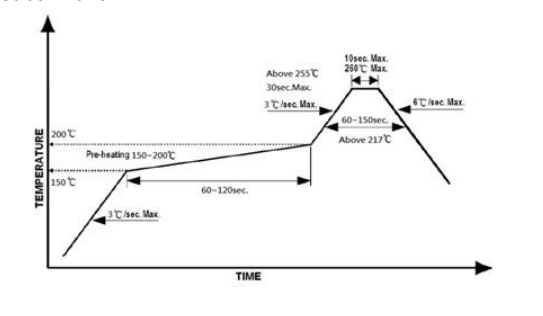
Reflow Soldering Recommend soldering paste specifications: 1. Operating temp.: Above 217℃ ,60 ~150sec. 2. Peak temp.:260 ℃Max.,10sec Max. 3. Reflow soldering should not be done more than two times. 4. Never attempt next process until the component is cooled down to room temperature after reflow. 5. The recommended reflow soldering profile (measured on the surface of the LED terminal) is as following: Lead-free Solder Profile
Reworking Rework should be completed within 5 seconds under 260 ℃. The iron tip must not come in contact with the copper foil. Twin-head type is preferred.
Cleaning Following are cleaning procedures after soldering: An alcohol-based solvent such as isopropyl alcohol (IPA) is recommended. Temperature x Time should be 50℃ x 30sec. or <30℃ x 3min Ultrasonic cleaning: < 15W/ bath; bath volume ≤ 1liter Curing: 100 ℃ max, <3min
| Official Product | HT Part No. B3DQ3BRG-05C0001L3U1930 | |||
|---|---|---|---|---|
| Tentative Product | **************** | **************** | ||
| Specifications are subject to changes for improvement without advance notice. Proprietary data, drawings, company confidential all rights reserved. | 04/14/2022 | Version 1.0 | Page 14/15 | |
Page 15
Cautions of Pick and Place Avoid stress on the resin at elevated temperature. Avoid rubbing or scraping the resin by any object. Electric-static may cause damage to the component. Please ensure that the equipment is properly grounded. Use of an ionizer fan is recommended.
Revise History
| Official Product | HT Part No. B3DQ3BRG-05C0001L3U1930 | |||
|---|---|---|---|---|
| Tentative Product | **************** | **************** | ||
| Specifications are subject to changes for improvement without advance notice. Proprietary data, drawings, company confidential all rights reserved. | 04/14/2022 | Version 1.0 | Page 15/15 | |