
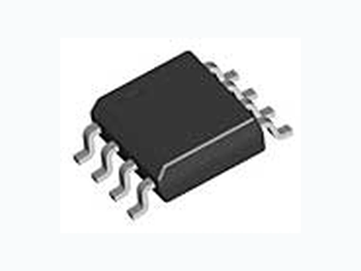
B3800M ETC1
Document overview
- Manufacturer or author: Provided By www.digicamel.com(FREE DATASHEET DOWNLOAD SITE)
- PDF pages: 10
Technical content
Features
- Wide operation from…………... 1.8 to 15V
- Low Current Consumption……… 5.5mA
- high Speed Operation ……………. 1MHz
- Incorporates soft start circuit
- Incorporates a stand-by function
- Incorporate a times-latch short circuit detection circuit (SCP)
- Totem-pole type output with adjustable on/off current (for NPN transistor)
- The error amplifier gain is set inside the IC, so peripheral components are minimized.
- Direct Replacement for MB3800
Applications
- Digital Camera
- MP3
- Low Battery Operating Applications Bay Linear Inspire the Linear Power 8-Pin Surface Mount To p V ie w -IN FB SCP 2 GND OUT OSC Vcc BR/ CTL 8-Pin Surface Mount To p V ie w -IN FB SCP 2 GND OUT OSC Vcc BR/ CTL
Bay Linear, Inc 2418 Armstrong Street, Livermore, CA 94550 Tel: (925) 606-5950, Fax: (925) 940-9556 www.baylinear.com B3800 PIN Description Pin No. Symbol I/O Description 1 -IN I Error amplifier inverting
2 SCP - Soft start and SCP setting capacitor connection pin
3 V CC - Power supply pin
4 BR/CTL I Output current setting and control pin
5 V OUT O Totem-pole type output pin
6 GND - Ground pin
7 OSC - Capacitor and resistor connection pin setting the oscillation frequency
8 FB O Error amplifier output pin
Parameter Symbol Value Unit Supply Voltage V CC 16 V Output source current I O + -50 mA Output sink current I O - 50 mA 570 mW 430 mW Allowable dissipation SOP-8, Ta≤+25°C SOP-8, Ta≤+25°C SSOP-8, Ta≤+25°C 580 mW Operating temperature T op -30 to +85 °C Storage temperature Tstg -55 to +125 °C WARNING: Semiconductor devices can be permanently damaged by application of stress (voltage, current, temperature, etc.) in excess of absolute maximum ratings. Do not exceed these ratings. Recommended Operating Condition Values Parameter Symbol Min Typ. Max. Unit Power Supply Voltage V CC 1.8 - 15 V Error amplifier input voltage V I -.0.2 - 1.0 V BR/CTL pin input voltage V BR -0.2 - V CC V Output source current I O + -40 - - mA Output sink current I O - - - 40 mA SCP pin capacitance C PE - 0.1 - µF Phase compensation capacitance C P - 0.1 - µF Output current setting resistance RB 150 390 5000 Ω Timing resistance RT 1.0 3.0 10.0 kΩ Timing Capacitance C T 100 270 10000 pF Oscillation frequency f OSC 10 500 1000 kHz Operation temperature TOP -30 +30 +85 °C WARNING: Recommended operating conditions are normal operating ranges for the semiconductor device. All the device’s electrical characteristics are warranted when operated within these ranges. Always use semiconductor devices within the recommended operating conditions. Operation outside these ranges may adversely affect reliability and could result in device failure. No warranty is made with respect to uses, operating conditions, or combinations not represented on the data sheet. Users considering application outside the listed conditions are advised to contact Bay Linear.
Bay Linear, Inc 2418 Armstrong Street, Livermore, CA 94550 Tel: (925) 606-5950, Fax: (925) 940-9556 www.baylinear.com B3800
Electrical Characteristics
Value Parameter Symbol Conditions Min. Typ. Max. Unit Reset Voltage V R - - 0.9 V Circuit to Prevent Malfunction at low input voltage (U.V.L.O.) Threshold voltage V TH 1.1 1.3 1.5 V Changing current ICS -1.5 -1.0 -0.7 µA Soft Start Voltage at soft start completion VTS VSCP=0V 0.7 0.8 0.9 V Charging current I cpc VSCP=0V -1.5 -1.0 -0.7 µA Short Circuit detection (OSC) Threshold voltage V PC - 0.7 0.8 0.9 V Oscillation freq. f ocs RT=3.0kΩ, CT=270pF 400 500 600 kH z Frequency input stability f dv VCC=2V to 15V - 2 10 % Sawtooth wave oscillator (OSC) Frequency variation with temperature fdt Ta=-30°C to +85°C - 5 - % Input threshold voltage VT VFB=450mV 480 500 520 mV VTinput stability V Tdv VCC= 2V to 15V - 5 20 mV VT variation with temperature VTDT Ta= -30°C to +85°C - 1 - % Input bias current I B VIN=0V -1.0 -0.2 1.0 µA Voltage gain AV - 70 100 145 V/ V Frequency bandwidth BW A V=0dB - 6 - M Hz Maximum output voltage range V OM VOM - - 0.78 0.87 0.05 0.2 V Output source current I OM + - -40 -24 µA Error amplifier Output sink current I OM _ VFB=0.45V 24 40 - µA Idle period adjustable section Maximum duty cycle tDUTY RT=3.0kΩ, CT=270pF VFB=0.8V 65 75 85 % VOH1 RB=390Ω, IO= -15mA 1.0 1.2 - V VOH2 RB=750Ω, IO= -10mA, VCC=1.8V 0.8 1.0 - V VOL1 RB=390Ω, IO=15mA - 0.1 0.2 V Output voltage VOL2 RB=750Ω, IO=10mA, VCC=1.8V - 0.1 0.2 V Output source current I O + RB=390Ω, VCC=0.9V - -30 -20 mA Output sink current I O - RB=390Ω, VCC=0.3V 30 60 - mA Output section Pull down resistance R O - 20 30 40 kΩ Pin Voltage V BR RB=390Ω, 0.2 0.3 0.4 V Input off condition I OFF -20 - 0 µA Input on condition I ON - - -45 µA Output current setting section/ Control section Pin current range I BR -1.8 - -0.1 mA Stand-by current I CCB BR/CTL pin open or Vcc - - 1 mA Entire device Average supply current ICC RB=390Ω, - 5.5 9.3 mA
Bay Linear, Inc 2418 Armstrong Street, Livermore, CA 94550 Tel: (925) 606-5950, Fax: (925) 940-9556 www.baylinear.com B3800 TIMMING DIAGRAM BLOCK DIAGRAM
Bay Linear, Inc 2418 Armstrong Street, Livermore, CA 94550 Tel: (925) 606-5950, Fax: (925) 940-9556 www.baylinear.com B3800 Typical Characteristics
Bay Linear, Inc 2418 Armstrong Street, Livermore, CA 94550 Tel: (925) 606-5950, Fax: (925) 940-9556 www.baylinear.com B3800 Typical Characteristics (continued)
Bay Linear, Inc 2418 Armstrong Street, Livermore, CA 94550 Tel: (925) 606-5950, Fax: (925) 940-9556 www.baylinear.com B3800 Typical Characteristics (continued) Bay Linear B3800
Bay Linear, Inc 2418 Armstrong Street, Livermore, CA 94550 Tel: (925) 606-5950, Fax: (925) 940-9556 www.baylinear.com B3800 Application Descriptions Power Supply Control Function Stand- by mode (supply current 1 mA or less) can be set by connecting the BR/ CTL pin (pin 4) to VCC or by making the pin open circuit. Switching Regulator Function Reference voltage circuit The reference voltage circuit generates a temperature- compensated reference voltage (@1.25V) from voltage supplied from the power supply pin (pin 3). In addition to providing the reference voltage for the switching regulator, the circuit also sets the idle period. Sawtooth wave oscillator The sawtooth oscillator generates a sawtooth wave (up to 1 MHz) that is stable with re spect to the supply voltage and temperature. The capacitor and resistor that set the oscillation frequency are connected to the OSC pin (pin 7). Error amplifier (Error Amp.) The error amplifier detects the output voltage of the switching regulator and outputs the PWM control signal. The voltage gain is fixed, and connecting a phase compensation capacitor to the FB pin (pin 8) provides stable phase compensation for the system. PWM comparator (PWM Comp.) The voltage comparator has one inverting and three non- inverting inputs. The comparator is a voltage/ pulse width converter that controls the ON time of the output pulse depending on the input voltage. The output level is high (H) when the sawtooth wave is lower than the error amplifier output voltage, soft start setting voltage, and idle period setting voltage. Output circuit The output circuit has a totem pole type configuration and can drive an external NPN transistor directly. The value of the ON/ OFF current can be set by a resistor connected to the BR/ CTL pin (pin 4). Other Functions Soft start and short circuit detection Soft start operation is set by connecting capacitor CPE to the SCP pin (pin 2). Soft start prevents a current spike on start- up. On completion of soft start operation, the SCP pin (pin 2) stays low and enters the short circuit detection wait state. When an output short circuit occurs, the error amplifier output is fixed at VOM+ and capacitor CPE starts charging. After charging to approximately 0.8 V, the output pin (pin 5) is set low and the SCP pin (pin 2) stays low. Once the protection circuit operates, the circuit can be restored by resetting the pow er supply. (See “n HOW TO SET THE TIME CONSTANT FOR SOFT START AND SHORT CIRCUIT DETECTION”.) Circuit to prevent malfunction at low input voltage Transients when powering on or instantaneous glitches in the supply voltage can lead to malfunction of the control IC and cause system damage or failure. The circuit to prevent malfunction at low input voltage detects a low input voltage by comparing the supply voltage to the internal reference voltage. On detection, the circuit fixes the output pin to low. The system recovers when th e supply voltage rises back above the threshold voltage of the malfunction prevention circuit.
Bay Linear, Inc 2418 Armstrong Street, Livermore, CA 94550 Tel: (925) 606-5950, Fax: (925) 940-9556 www.baylinear.com B3800 HOW TO SET THE TIME CONSTANT FOR SOFT START AND SHORT CIRCUIT DETECTION Soft Start At power on, the capacitor CPE connected to the SCP pin starts charging. The PWM comparator compares the soft start setting voltage as a proportion of the voltage at the SCP pin with the sawtooth waveform. Th e comparison controls the ON duty of the OUT pin, causing the soft start operation. On completion of soft start operati on, the voltage at the SCP pin stays low, the soft start setting voltage stays high, and the circuit enters the output short ci rcuit detection wait state. Soft start time (The time until the output ON duty reaches approximately 50%) tS [s] @ 0.35 ´ CPE [mF] Short Circuit Protection If the switching regulator output suddenly drops due to load effect, the error amplifier output (FB pin) is fixed at VOM + and capacitor CPE starts charging. When the voltage at the SCP pin reac hes approximately 0.8V, the output pin is set low and the SCP pin stays low. Once the protection circuit operates, the circuit can be restored by resetting the power supply. • Short circuit detection time TPE [s] @ 0.8 ´ CPE [mF] APPLICATION DIAGRAM B3800
Bay Linear, Inc 2418 Armstrong Street, Livermore, CA 94550 Tel: (925) 606-5950, Fax: (925) 940-9556 www.baylinear.com B3800 8 pin SOIC Advance Information- These data sheets contain descriptions of products that are in development. The specifications are based on the engineering ca lculations, computer simulations and/ or initial prototype evaluation. Preliminary Information- These data sheets contain minimum and maximum specifications th at are based on the initial devi ce characterizations. These lim its are subject to change upon the completion of the full characterization over the specified temperature and supply voltage ranges. The application circuit examples are only to explain the repres entative applications of the devices and are not intended to gua rantee any circuit design or permit any industrial property right to other rights to execute. Bay Linear takes no responsibility for any problems related to any industrial property right resulting from the use of the contents shown in the da ta book. Typical parameters can and do vary in different applications. Customer’s technical experts must validate all operating parameters including “ Typical” for each customer application. LIFE SUPPORT AND NUCLEAR POLICY Bay Linear products are not authorized fo r and should not be used within life suppor t systems which are intended for surgical implants into the body to support or sustain life, in aircraft, space equipment, submarine, or nuclear facility applications wi thout the specific written consent of Bay Linear President. Pin 1 1.27 (0.50) BSC 3.8 (0.150) 4.0 (0.158) 4.6 (0.181) 5.2 (0.205) 5.8 (0.228) 6.2 (0.244) 4.8 (0.188) 5.0 (0.197) 0.49 (0.019) 0.56 (0.022) 0.35 (0.014) 0.45 (0.018) 0.10 (0.004) 0.22 (0.009) 1.35 (0.053) 1.75 (0.069) 0.61 (0.024) 0.78 (0.031) 3°-6° 0.64 (0.025) 0.77 (0.030) 45° 7 °(4 PLCS) BSC