
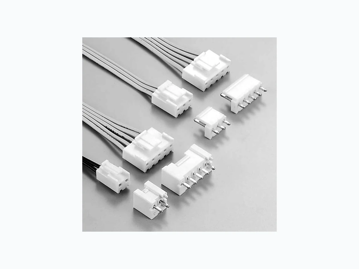
B5P-VH ETC2
Document overview
- Manufacturer or author: Provided By www.digicamel.com(FREE DATASHEET DOWNLOAD SITE)
- PDF pages: 5
Technical content
This small, field-proven connector for printed circuit boards is reliable and has a large current carrying capacity. It can be used with a wide variety of signal, power supply, and output circuits that appear in consumer electronic products.
- Proven box contact This connector was developed with the same box-shaped contact design used successfully in the NH connectors. The reliable VH connector can be used in a wide variety of applications, from low-voltage, low-current signal circuits to power supply circuits having a relatively large capacity.
- Compact connector with a large capacity Even though this connector has a large current carrying capacity (10A), it is compact, with a mounting height of 16.5mm (.650").
- Secure contact and mounting The housing has a lock mechanism which prevents the connector from coming loose due to vibration. The mechanism also prevents misinsertion (misalignment or reverse insertion).
- Current rating: 10A AC, DC (AWG#16)
- Voltage rating: 250V AC, DC
- Temperature range: -25˚C to +85˚C (including temperature rise in applying electrical current)
- Contact resistance: Initial value/10m Ω max. After environmental testing/20m Ω max.
- Insulation resistance: 1,000M Ω min.
- Withstanding voltage: 1,500V AC/minute
- Applicable wire: AWG #22 to #16
- Applicable PC board thickness: 1.6mm(.063") Note: Do not branch in parallel current which exceeds the rated current. If branched in parallel, current imbalance or other problems may develop. If it is absolutely necessary to branch such a large current in parallel, be sure to use contacts made of phosphor bronze. Design the circuits without causing imbalance and provide an extra margin for each circuit. * Contact JST if Lead-Free product is required. * Temperature Range: The aforementioned temperature range of this connector is described in JST Standard Product Specification. Maximum temperature registered in UL is 105˚C. * Refer to "General Instruction and Notice when using Terminals and Connectors" at the end of this catalog. * Contact JST for details. 0Recognized E60389 1Certified LR20812 2R75122 VH CONNECTOR Disconnectable Crimp style connectors3.96mm (.156") pitch Crimp
10.6(.417) 3.8(.150) B A 5.7 (.224) 13.3(.524) B A 6.2(.244) 10.6(.417) 14.8(.583) 5.7(.224) 10.5(.413) B A Circuit No.1 Circuit No.1 Circuit No.1 Model No. Applicable wire mm 2 AWG # Insulation O.D. mm(in.) Material and Finish Q'ty / reel SVH-21T-P1.1 SVH-41T-P1.1 0.33 to 0.83 0.5 to 1.25 22 to 18 20 to 16 1.7 to 3.0 (.067 to .118) 1.7 to 3.0 (.067 to .118) 4,500 3,500 Phosphor bronze, tin-plated N type M type Cir- cuits Model No. N type M type Dimensions mm(in.) AB Q'ty / bag Material VHR-2N VHR-3N VHR-4N VHR-5N VHR-6N VHR-7N VHR- 8N VHR- 9N VHR-10N VHR-11N VHR-2M VHR-3M VHR-4M VHR-5M VHR-6M VHR-7M VHR-9M Retainer mountable type VHRR-2N VHRR-3N VHRR-5N VHRR-7N VHRR-8N VHRR-9N 3.96( .156) 7.92( .312) 11.88( .468) 15.84( .624) 19.80( .780) 23.76( .935) 27.72(1.091) 31.68(1.247) 35.64(1.403) 39.60(1.559) 7.86( .309) 11.82( .465) 15.78( .621) 19.74( .777) 23.70( .933) 27.66(1.089) 31.62(1.245) 35.58(1.401) 39.54(1.557) 43.50(1.713) 1,000 1,000 1,000 1,000 500 500 500 500 500 500 Nylon 6, UL94V-0, natural (white) Retainer mountable type VH CONNECTOR Note: 1. Contact JST if you require contacts made of brass. 2. When using retainer mountable type housing, applicable wire's Note: 1. Models identified as VHR-( ) M incorporate measures to prevent electric shock and are thus safer in regard to high voltages. 2. The applicable housing for 2-circuits shrouded header is "VHR-2N" only. "VHRR-2N" is not applicable. 3. Models VHR-11N and VHRR-( )N are not TU¨V approved. <For reference> As the color identification, the following alphabet shall be put in the underlined part. For availability, delivery and minimum order quantity, contact JST. ex. VHR-2N-oo - (blank)…natural (white) BK…black R…red BL…blue M…green D…orange Y…yellow PK…pink H…gray
A B 1.14(.045) 14.6(.575) 7.7 (.303) 2.0(.079) 8.5(.335) [9.4(.370)] A B 14.9(.587) 7.7 (.303) 3.2 (.126) 8.5(.335) [9.4(.370)] 3.96 (.156) 2.0(.079) Circuit No.1 Circuit No.1 1.14 (.045) 3.2 (.126) Cir- cuits Model No. Dimensions mm(in.) Q ’ty / box ABTop entry type Side entry type Top entry type Side entry type Material and Finish B 2P-VH B 3P-VH B 4P-VH B 5P-VH B 6P-VH B 7P-VH B 8P-VH B 9P-VH B10P-VH B 2PS-VH B 3PS-VH B 4PS-VH B 5PS-VH B 6PS-VH B 7PS-VH B 8PS-VH B 9PS-VH B10PS-VH 3.96( .156) 7.92( .312) 11.88( .468) 15.84( .624) 19.80( .780) 23.76( .935) 27.72(1.091) 31.68(1.247) 35.64(1.403) 7.86( .309) 11.82( .465) 15.78( .621) 19.74( .777) 23.70( .933) 27.66(1.089) 31.62(1.245) 35.58(1.401) 39.54(1.557) 1,000 1,000 500 500 250 250 200 200 200 1,000 500 500 250 250 250 200 200 200 Post: Brass, copper-undercoated, tin/lead-plated Wafer: Nylon 66, UL94V-0, natural (white) Top entry type Side entry type Note: Headers with a reduced number of posts are also available. Contact JST for details. A 7.1(.280) 2 circuits : 2.6(.102) 3 to 9 circuits : 4.2(.165) Circuits Model No. Q'ty / bag VHS-2V VHS-3V VHS-5V VHS-7V VHS-8V VHS-9V A 3.70(1.146) 7.52(1.296) 15.44(1.608) 23.36(1.920) 27.32(1.076) 31.28(1.231) 1,000 1,000 1,000 1,000 1,000 1,000 Material Glass-filled nylon 66, UL94V-0, natural (ivory) Note: Not TU¨V approved. VH CONNECTOR <For reference> As the color identification, the following alphabet shall be put in the underlined part. For availability, delivery and minimum order quantity, contact JST. ex. B2P(S)-VH-oo- (blank)…natural (white) BK…black R…red TR…tomato red BL…blue M…green O…orange Y…yellow PK…pink H…gray
A B [9.4(.370)] 8.5(.335) [1.95 (.077)] [1.95 (.077)] 6.8 (.268) 1.7 (.067) [14.6(.575)] (.126) 7.7 (.303) 3.2 1.14(.045) B 4.8(.189) A 7.7 (.303) 3.6 (.142) 1.14 (.045) Circuit No.1 Circuit No.1 [9.4(.370)] 4.5 (.177) 13.4(.528) Cir- cuits Model No. Dimensions mm(in.) Q'ty / box ABTop entry type of PBT Top entry type Side entry type Material and Finish Side entry type with PCB stabilizer B 2P-VH-B B 3P-VH-B B 4P-VH-B B 5P-VH-B B 6P-VH-B B 7P-VH-B B 8P-VH-B B 9P-VH-B B10P-VH-B B11P-VH-B S2P-VH S3P-VH S4P-VH S5P-VH S7P-VH 3.96( .156) 7.92( .312) 11.88( .468) 15.84( .624) 19.80( .780) 23.76( .935) 27.72(1.091) 31.68(1.247) 35.64(1.403) 39.60(1.559) 7.86( .309) 11.82( .465) 15.78( .621) 19.74( .777) 23.70( .933) 27.66(1.089) 31.62(1.245) 35.58(1.401) 39.54(1.557) 43.50(1.713) 1,000 500 500 250 250 250 200 200 200 1,000 500 500 250 250 Post: Brass, copper-undercoated, tin/lead-plated Wafer: Top entry type of PBT: Glass-filled PBT, UL94V-0, natural (ivory) Side entry type with PCB stabilizer: Nylon 66, UL94V-0, natural (white) Circuits Model No. Dimensions mm(in.) AB Material and Finish Q'ty / box 3.96( .156) 7.92( .312) 11.88( .468) 15.84( .624) 19.80( .780) 23.76( .935) 27.72(1.091) 31.68(1.247) 35.64(1.403) 250 200 150 200 200 100 100 100 125 9.80( .386) 13.76( .542) 17.72( .698) 21.68( .854) 25.64(1.009) 29.60(1.165) 33.56(1.321) 37.52(1.477) 41.48(1.633) B 2P-VH-FB-B B 3P-VH-FB-B B 4P-VH-FB-B B 5P-VH-FB-B B 6P-VH-FB-B B 7P-VH-FB-B B 8P-VH-FB-B B 9P-VH-FB-B B10P-VH-FB-B Post: Brass, copper-undercoated, tin/lead-plated Wafer: Glass-filled PBT, UL94V-0, natural (white) Top entry type of PBT 11.0(.433) 1.5(.059) B 9.7(.382) 3.7 (.146) A Circuit No.1 1.14(.045) B 1.5(.059) A 3.96 (.156) 11.0(.433) 9.7(.382) 3.7 (.146) Circuit No.1 1.14(.045) (2 , 3 circuits) (4 to 10 circuits) Side entry type with PCB stabilizer Note : B11P-VH-B is not TU¨V approved. <For reference> As the color identification, the following alphabet shall be put in the underlined part. For availability, delivery and minimum order quantity, contact JST. <Top entry type of PBT> ex. B2P-VH-B-oo - (blank)…natural (ivory) C…black R…red E…blue M…green Y…yellow <Side entry type with PCB stabilizer> ex. S2P-VH-oo - (blank)…natural (white) BK…black R…red BL…blue Y…yellow M…green Note : The applicable housing for 2-circuits shrouded header is "VHR-2N" only. "VHRR-2N" is not applicable. <For reference> As the color identification, the following alphabet shall be put in the underlined part. For availability, delivery and minimum order quantity, contact JST. ex. B2P-VH-FB-B-oo - (blank)…natural (white) R…red C…black E…blue M…green Y…yellow O…orange H…gray PK…pink
10.5(.413) 16.5(.650) 1.65+0.1 (.065+.004)dia. 20.5(.807) (.283) 1.65+0.1 (.065+.004)dia. *7.2 min. 8.0 (.315) *7.2 min.(.283) 10.5 (.413) 21.0(.827) 19.0(.748) 1.65+0.1 (.065+.004)dia. 1.65+0.1 (.065+.004 0 )dia. 10.5 (.413) *11.0(.433) max. when used with the VR connector receptacle. 10.5(.413) 16.5(.650) 1.5(.059) 3.4±0.05 (.134.002) 1.4+0.1 (.055+.004 0 )dia. Circuit No.1 3.96 ± 0.05 (.156 ± .002) 3.96 ± 0.05 (.156 ± .002) 3.96 ± 0.05 (.156 ± .002) 3.96 ± 0.05 (.156 ± .002) Note: 1. Tolerances are non-cumulative: ±0.05mm(±.002) for all centers. 2. Hole dimensions differ according to the kind of PC board and piercing method. The dimensions above should serve as a guideline. Contact JST for details. Locking header Top entry type Locking header Side entry type Locking header Side entry type with PCB stabilizer Shrouded header VH CONNECTOR Contact Crimp applicator MKS-L Compact crimp applicator MKS-LS Strip-crimp applicator MKS-SC with safety cover without safety cover with safety cover without safety cover with safety cover SVH-21T-P1.1 APLMK SVH21-11 APLNC SVH21-11 –– APLSC SVH21-11 SVT-41T-P1.1 APLMK SVT41-11 APLNC SVT41-11 –– –