
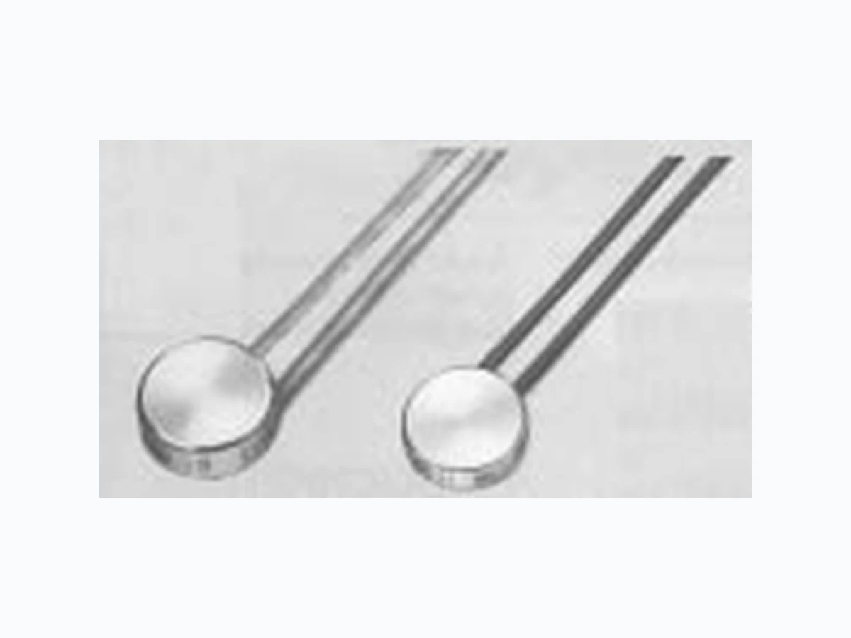
B12 ETC2
Document overview
- Manufacturer or author: Provided By www.digicamel.com(FREE DATASHEET DOWNLOAD SITE)
- PDF pages: 4
Technical content
DESCRIPTION
This thermostat operates as a thermal cutout.A thermally sensitive bimetal snap-element with double contacts (single contacts for type F 11) either opens or closes an electrical circuit by switching at a pre-set res- ponse temperature. Reset follows automatically after a considerable drop in temperature. Heat transfer occurs from all sides through convection, radiation or con- duction in gaseous or solid media. The circular base plate conducts heat onto the bimetal snap-element, thus also allowing its use as a surface temperature cutout.
APPLICATIONS
Thermal protection and- under certain conditions - temperature control of electrical machinery and equipment. Examples Single phase motors Heating elements Chokes Generators Signal transmitters Coils Convertors Fire detectors Power supplies Transformers Magnets Inverters Pumps Relays DIMENSIONS F 11 B 11/B 12 M icrotherm International C ooperation Thermal Cutout Temperature Protection for Coils/Windings
FEATURES
– broad product range for all types of application and load – small size – maximum switch load – good heat transfer – high temperature sensitivity – minimal contact resistance – many approvals F Type B Type 03-04-01 1000-Y132
8415 Mountain Sights Avenue • Montreal (Quebec), H4P 2B8, Canada
Tel: (514) 739-3274 • 1-800-561-7207 • Fax: (514) 739-290 E-mail : sales@cantherm.com • Website: www.cantherm.com
The thermostats are not current sensitive at rated currents. At loads above the rated values, upto maximum loading there is self-heating of the cur- rent-carrying contacts. If current sensitive cutouts are required, please refer to the data sheet „Thermal cutouts – current sensitive thermal protection for coils/windings (Nr. 395). INSULATION RESISTANCE Housing (with insulation) to earth 2750Veff. AC P302 On request, in special housing, upto 4000Veff. AC P304 Across open contacts, dependent on response temperature 500Veff. AC P304 Voltage of coil depending on application, please ask. CONNECTIONS Flexible leads or solid wire in different lengths and cross-sections are available – please ask. RESPONSE TEMPERATURES, TOLERANCE Temperature stepped in 5 °C intervals, and toleran- ce in K from 50 °C to 160 °C. Special switch-off and reset temperatures available on request. Rate of temperature rise from 0.1 K/min. to max. 1.0 K/min. Insulation of the housing will slow down the cutout’s response. Standard reset temperature between 5 K and 50 K, depending on response temperature. QUALITY ASSURANCE Production item testing Voltage test, switch function Nominal switching temperature Random sample quality testing Life expectancy to VDE 0631/EN 60730 Function test to AQL 1.0 Nominal response temperature AQL 1.0 Measurement tolerance ±2 °C AQL 4.0 Other values AQL 4.0 Type F 11 F 11U B 11 B 12 Voltage rating 50 – 60 Hz* 250 V 250 V 250 V 250 V Current rating at cos j = 1,0* 2,0 A 2,0 A 6,3 A 6,3 A Current rating at cos j = 0,6* 1,2 A 1,2 A 4,0 A 4,0 A max. load 48h** at cos j = 1.0 3,0 A 4,0 A 8,0 A 10,0 A Contact Normally closed N-C arrangementNormally open N-O Switch operations at rated current* E I (10 000) E I (10 000) 35E2 (3500) E I (10 000) E I (10 000) Contact resistance*** < 40 m ½ < 40 m½ < 40 m½ < 40 m½ Response temperature range +70 °C to +70 °C to +50 °C to +50 °C to
343 K to 433 K 343 K to 433 K 323 K to 433 K 323 K to 433 K
Tolerance (minimum) ±5 K ±10 K ±15 K ±5 K ±10 K ±15 K ±5 K ±10 K ±15 K ±5 K ±10 K ±15 K Max. permanent temperature of switch mechanism* T 175 T 175 T175 T 175 Housing material silver-plated steel silver-plated steel nickel-plated steel nickel-plated steel hard epoxy hard epoxy Duroplast Duroplast Protection sealed against ingress of dust, lacquer, oil, resin etc. Strength of shape without permanent deformation 800 N/mm 2 800 N/mm 2 900 N/mm 2 900 N/mm 2 Vacuum tightness Æ standard standard standard standard Ref. P102 Ref. P102 Ref. P102 Ref. P102 bar cm3/s bar cm 3/s bar cm 3/s bar cm 3/s Standard 1250 V 50–60 Hz Insulation resistance/ P301 2000 V 50–60 Hz dielectric strength P302 2750 V 50–60 Hz Execution according to U P303 3750 V 50–60 Hz P304 4000 V 50–60 Hz Overheat protector ÜHS 10,0 (1,2) A 16,0 (8,0) A Short circuit proof 10,0 A 10,0 A 36,0 A 36,0 A 110 V AC 6.0 A 6.0 A 12.0 A 12.0 A 60 V DC 1.0 A 1.0 A 3.0 A 3.0 A 42 V DC 1.2 A 1.2 A 4.2 A 4.2 A 6/12/24 V DC 1.8 A 1.8 A 5.5 A 5.5 A Min. load 50 m A 50 m A 50 m A 50 m A TECHNICAL DATA Note: *Approved ratings- other specific values on request. . * Contact resistance in standard version. ***Cycling rate 72/h Æ On request.
Type Lead length Code Class Cross section Coating/ Conductor Colourstandard (VDE) Insulation L510 B 0.25 mm 2 Textil/Lack tinned copper black F 11 100 –20 mm L517 F 0.25 mm 2 Polyolefine tinned copper blue L515 C 0.24 mm 2 PTFE silvered copper white L520 B 0.5 mm 2 Textil/Lack tinned copper yellow B 11/ 100–20 mm L531 F 0.5 mm 2 Polyolefine tinned copper blue B 12 L528 H 0.5 mm 2 FEP tinned copper white L540 C 0.62 mm 2 PTFE silvered copper white Lead stripping: standard 6 ±1 mm a = ends stripped b = half insulated c = stripped and lead end tinned INSULATION Standard versions of the thermostats are un-insula- ted. If insulation is desired, the standard insulation (class) should be selected for the appropriate res- ponse temperature or max. operating temperature. Example: The temperature resistance of the connecting leads allows for the nominal response temperature of the cutout. The leads used are consistent with insulation class and dielectric strength stated. CONNECTIONS (Standard) U1 02 (F 1 1 ) U112 (F11 ) U1 85 (F 1 1 ) U105 (B 11/B 12 ) U 1 1 2 (B 1 1/B 1 2 ) U 1 86(B 11/B 12 ) Type Version Description Insulation Class (VDE) Standard F 11 U 102 SHB transparent shrink B material F 11 U 104 SSB radiation cross-linked B heat-shrink sleeve black for normally closed F 11 U 106 SSH radiation cross-linked F heat-shrink sleeve transparent F 11 U 116 Standard H shrink sleeve PTFE F 11 U 112 UWF coating F hard epoxy F 11 U 185 Standard B Insulation cap ST F 11 U 180 Insulation cap PET H Standard B 11/B 12 U 103 SHB transparent shrink B material B 11/B 12 U 105 SSB radiation cross-linked B heat-shrink sleeve black for normally closed U 109 red for normally open B 11/B 12 U 107 SSH radiation cross-linked F heat-shrink sleeve transparent B 11/B 12 U 139 shrink sleeve PTFE H B 11/B 12 U 112 UWF coating F hard epoxy Standard B 11/B 12 U 186 Insulation cap ST B B 11/B 12 U 181 Insulation cap PET H
Special versions are available, please ask. MOUNTINGS Single screw fixing bracket (CuBe) for use on flat surfaces with full insulation or cap. INSTALLATION TIPS When installing thermal cutouts, it is important to ensure good heat transfer. The heat sensitive surfa- ce (base) should be placed on/near to the heat sour- ce. Heat conducting paste or paint will improve heat transfer. It should be noted that standard version thermal cut- outs have a current-carrying housing, and that with electrically insulated cutouts the impaired heat transfer can alter the effective switching temperatu- re. This should be borne in mind when selecting the nominal response temperature. With single-phase motors, the cutout should switch the mains supply. It will then switch the motor off if there is any undesirable heating. The motor short circuit current will then be safely interrupted, if this is larger than the current rating of the cutout. For three-phase motors, the motor current will not be interrupted direct from the mains supply. The cutout installed in the windings should switch in series with the magnetic coil of the contactor. The electrical supply to the cutouts should lead either singly or together from the motor terminals so that connection with the control circuit is possible. PRODUCT MARKING Example: B12V Type, version
12510 Nominal response temperature
(3 digits), Tolerance ± in K (2 digits) 074E Month (2 digits), Y ear (1 digit), Country code MARKING Normally closed = blue epoxy, Code No. 2 Normally open = red epoxy, Code No. 1 Special markings on request. APPROVALS Life expectancy, voltage rating, current rating to VDE 0631 or EN 60730, see page 2. Additional approvals apply for many countries. Information on request. ORDERING EXAMPLE Quantity Type Temperature Version
800 B 12 125 °C ±10 K U 103
We reserve the right to change specifications without prior notice. Tel: (514) 739-3274 • 1-800-561-7207 • Fax: (514) 739-290 E-mail : sales@cantherm.com • Website: www.cantherm.com