

 Download PDF
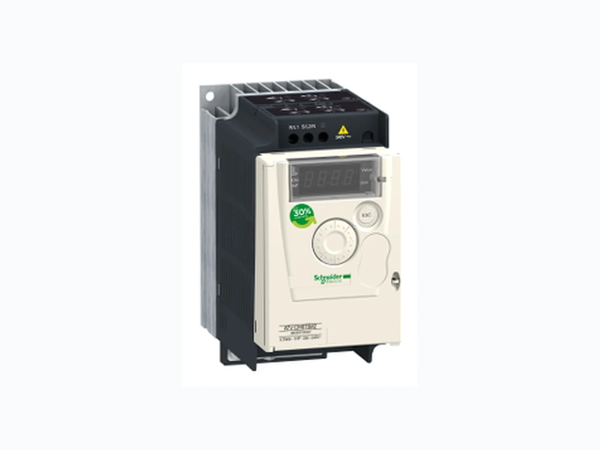
ATV12H075M2 SCHNEIDER
Document overview
- PDF pages: 10
Technical content
Page 1
variable speed drive ATV12 - 0.75kW - 1hp -
Characteristics
200..240V - 1ph - with heat sink
Main
Range of product
Altivar 12
Product or component type
Variable speed drive
Product destination
Asynchronous motors
Product specific application
Simple machine
Assembly style
With heat sink
Component name
ATV12
Quantity per set
Set of 1
EMC filter
Integrated
Built-in fan
Without
Network number of phases
1 phase
[Us] rated supply voltage
200...240 V - 15...10 %
Motor power kW
0.75 kW
Motor power hp
1 hp
Communication port protocol
Modbus
Line current
10.2 A at 200 V 8.5 A at 240 V
Speed range
1…20 150…170 % of nominal motor torque depending on drive rating and type of motor
Transient overtorque Asynchronous motor control profile
Quadratic voltage/frequency ratio Voltage/frequency ratio (V/f) Sensorless flux vector control IP20 without blanking plate on upper part
IP degree of protection Noise level
0 dB
Complementary
Supply frequency
50/60 Hz +/- 5 %
Connector type
1 RJ45 (on front face) for Modbus
May 14, 2021
Page 2
Physical interface
2-wire RS 485 for Modbus
Transmission frame
RTU for Modbus
Transmission rate
4800 bit/s 9600 bit/s 19200 bit/s 38400 bit/s
Number of addresses
1…247 for Modbus
Communication service
Read holding registers (03) 29 words Write single register (06) 29 words Write multiple registers (16) 27 words Read/write multiple registers (23) 4/4 words Read device identification (43)
Prospective line Isc
1 kA
Continuous output current
4.2 A at 4 kHz
Maximum transient current
6.3 A for 60 s
Speed drive output frequency
0.5…400 Hz
Nominal switching frequency
4 kHz
Switching frequency
2...16 kHz adjustable 4...16 kHz with derating factor Up to 70 % of nominal motor torque without braking resistor
Braking torque Motor slip compensation
Preset in factory Adjustable
Output voltage
200...240 V 3 phases Terminal, clamping capacity: 3.5 mm², AWG 12 (L1, L2, L3, U, V, W, PA, PC)
Electrical connection Tightening torque
0.8 N.m
Insulation
Electrical between power and control Internal supply for reference potentiometer: 5 V DC (4.75…5.25 V), <10 mA, protection type:
Supply
overload and short-circuit protection Internal supply for logic inputs: 24 V DC (20.4…28.8 V), <100 mA, protection type: overload and short-circuit protection
Analogue input number
1 Configurable current AI1 0...20 mA 250 Ohm
Analogue input type
Configurable voltage AI1 0...10 V 30 kOhm Configurable voltage AI1 0...5 V 30 kOhm
Discrete input number
4 Programmable LI1...LI4 24 V 18...30 V
Discrete input type
Negative logic (sink), > 16 V (state 0), < 10 V (state 1), input impedance 3.5 kOhm
Discrete input logic
Positive logic (source), 0...< 5 V (state 0), > 11 V (state 1) 20 ms, tolerance +/- 1 ms for logic input
Sampling duration
10 ms for analogue input +/- 0.3 % of maximum value for analogue input
Linearity error Analogue output number
1 AO1 software-configurable voltage: 0...10 V, impedance: 470 Ohm, resolution 8 bits
Analogue output type
AO1 software-configurable current: 0...20 mA, impedance: 800 Ohm, resolution 8 bits
Discrete output number
2
Discrete output type
Logic output LO+, LO- Protected relay output R1A, R1B, R1C 1 C/O
Minimum switching current
5 mA at 24 V DC for logic relay 2 A 250 V AC inductive cos phi = 0.4 L/R = 7 ms logic relay
Maximum switching current
2 A 30 V DC inductive cos phi = 0.4 L/R = 7 ms logic relay 3 A 250 V AC resistive cos phi = 1 L/R = 0 ms logic relay 4 A 30 V DC resistive cos phi = 1 L/R = 0 ms logic relay
Acceleration and deceleration ramps
Linear from 0 to 999.9 s U S
Braking to standstill
By DC injection, <30 s
Protection type
Line supply overvoltage Line supply undervoltage Overcurrent between output phases and earth Overheating protection Short-circuit between motor phases
Page 3
Against input phase loss in three-phase Thermal motor protection via the drive by continuous calculation of I²t Analog input: converter A/D, 10 bits
Frequency resolution
Display unit: 0.1 Hz 20 ms +/- 1 ms for reference change
Time constant Marking
CE
Operating position
Vertical +/- 10 degree
Height
143 mm
Width
72 mm
Depth
131.2 mm
Net weight
0.8 kg
Functionality
Basic
Specific application
Commercial equipment
Variable speed drive application
Commercial equipment Mixer Commercial equipment Other application
selection
Textile Ironing
Motor starter type
Variable speed drive
Environment
Electrical fast transient/burst immunity test level 4 conforming to EN/IEC 61000-4-4
Electromagnetic compatibility
Electrostatic discharge immunity test level 3 conforming to EN/IEC 61000-4-2 Immunity to conducted disturbances level 3 conforming to EN/IEC 61000-4-6 Radiated radio-frequency electromagnetic field immunity test level 3 conforming to EN/IEC 61000-4-3 Surge immunity test level 3 conforming to EN/IEC 61000-4-5 Voltage dips and interruptions immunity test conforming to EN/IEC 61000-4-11 Radiated emissions environment 1 category C2 conforming to EN/IEC 61800-3 2...16 kHz shielded
Electromagnetic emission
motor cable Conducted emissions with integrated EMC filter environment 1 category C1 conforming to EN/IEC 61800-3 2, 4, 8, 12 and 16 kHz shielded motor cable <5 m Conducted emissions with integrated EMC filter environment 1 category C2 conforming to EN/IEC 61800-3 2...12 kHz shielded motor cable <5 m Conducted emissions with integrated EMC filter environment 1 category C2 conforming to EN/IEC 61800-3 2, 4 and 16 kHz shielded motor cable <10 m Conducted emissions with additional EMC filter environment 1 category C1 conforming to EN/IEC 61800-3 4...12 kHz shielded motor cable <20 m Conducted emissions with additional EMC filter environment 1 category C2 conforming to EN/IEC
61800-3 4...12 kHz shielded motor cable <50 m Conducted emissions with additional EMC filter environment 2 category C3 conforming to EN/IEC 61800-3 4...12 kHz shielded motor cable <50 m
Product certifications
NOM UL GOST C-Tick CSA 1 gn (f = 13…200 Hz) conforming to EN/IEC 60068-2-6
Vibration resistance
1.5 mm peak to peak (f = 3…13 Hz) - drive unmounted on symmetrical DIN rail - conforming to EN/ IEC 60068-2-6 15 gn conforming to EN/IEC 60068-2-27 for 11 ms
Shock resistance
5…95 % without condensation conforming to IEC 60068-2-3
Relative humidity
5…95 % without dripping water conforming to IEC 60068-2-3
Ambient air temperature for storage
-25…70 °C -10…40 °C protective cover from the top of the drive removed
Ambient air temperature for operation
40…60 °C with current derating 2.2 % per °C > 1000...2000 m with current derating 1 % per 100 m
Operating altitude
<= 1000 m without derating
Packing Units
Unit Type of Package 1
PCE
Number of Units in Package 1 Package 1 Weight
1.11 kg
Package 1 Height
11.7 cm
Package 1 width
19 cm
Page 4
Package 1 Length
19.5 cm
Unit Type of Package 2
CAR
Number of Units in Package 2
1
Package 2 Weight
1.128 kg
Package 2 Height
11.7 cm
Package 2 width
19 cm
Package 2 Length
19.5 cm
Unit Type of Package 3
P06
Number of Units in Package 3
45
Package 3 Weight
63.09 kg
Package 3 Height
80 cm
Package 3 width
80 cm
Package 3 Length
60 cm
Offer Sustainability
Sustainable offer status
Green Premium product
REACh Regulation
REACh Declaration Pro-active compliance (Product out of EU RoHS legal scope)
EU RoHS Directive
EU RoHS Declaration
Mercury free
Yes
RoHS exemption information
Yes
China RoHS Regulation
China RoHS declaration
Environmental Disclosure
Product Environmental Profile
Circularity Profile
End of Life Information The product must be disposed on European Union markets following specific waste collection and
WEEE
never end up in rubbish bins WARNING: This product can expose you to chemicals including: Lead and lead compounds, which
California proposition 65
is known to the State of California to cause cancer and birth defects or other reproductive harm. For more information go to www.P65Warnings.ca.gov
Contractual warranty
Warranty
18 months
Page 5
Dimensions Drawings
Dimensions
Drive without EMC Conformity Kit
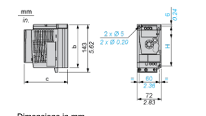
Dimensions in mm
| b | c | H |
| 130 | 131.2 | 120 |
Dimensions in in.
| b | c | H |
| 5.12 | 5.16 | 4.72 |
Drive with EMC Conformity Kit
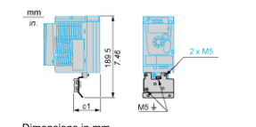
Dimensions in mm
c1
63
Dimensions in in.
c1
2.48
Page 6
Mounting and Clearance
Mounting Recommendations
Clearance for Vertical Mounting
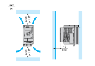
Mounting Type A
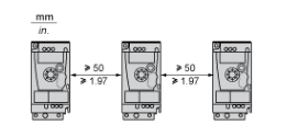
Mounting Type B
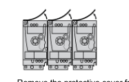
Remove the protective cover from the top of the drive.
Mounting Type C
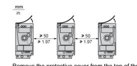
Remove the protective cover from the top of the drive.
Page 7
Connections and Schema
Single-Phase Power Supply Wiring Diagram
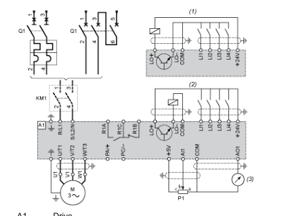
A1 Drive KM1 Contactor (only if a control circuit is needed) 2.2 kΩ reference potentiometer. This can be replaced by a 10 kΩ potentiometer (maximum). P1 Q1 Circuit breaker (1) Negative logic (Sink) (2) Positive logic (Source) (factory set configuration) (3) 0...10 V or 0...20 mA
Page 8
Connections and Schema
Recommended Schemes
2-Wire Control for Logic I/O with Internal Power Supply
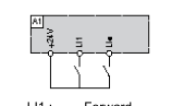
LI1 : Forward LI• : Reverse A1 : Drive
3-Wire Control for Logic I/O with Internal Power Supply
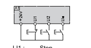
LI1 : Stop LI2 : Forward LI• : Reverse A1 : Drive
Analog Input Configured for Voltage with Internal Power Supply
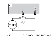
(1) 2.2 kΩ…10 kΩ reference potentiometer A1 : Drive
Analog Input Configured for Current with Internal Power Supply
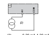
(2) 0-20 mA 4-20 mA supply A1 : Drive
Page 9
Connected as Positive Logic (Source) with External 24 vdc Supply
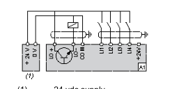
(1) 24 vdc supply A1 : Drive
Connected as Negative Logic (Sink) with External 24 vdc supply
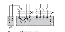
(1) 24 vdc supply A1 : Drive
Page 10
Performance Curves
Torque Curves
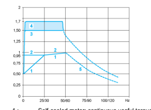
1 : Self-cooled motor: continuous useful torque (1) 2 : Force-cooled motor: continuous useful torque 3 : Transient overtorque for 60 s 4 : Transient overtorque for 2 s 5 : Torque in overspeed at constant power (2) For power ratings ≤ 250 W, derating is 20% instead of 50% at very low frequencies. (1) The nominal motor frequency and the maximum output frequency can be adjusted from 0.5 to 400 Hz. The mechanical overspeed capability of the selec (2)