
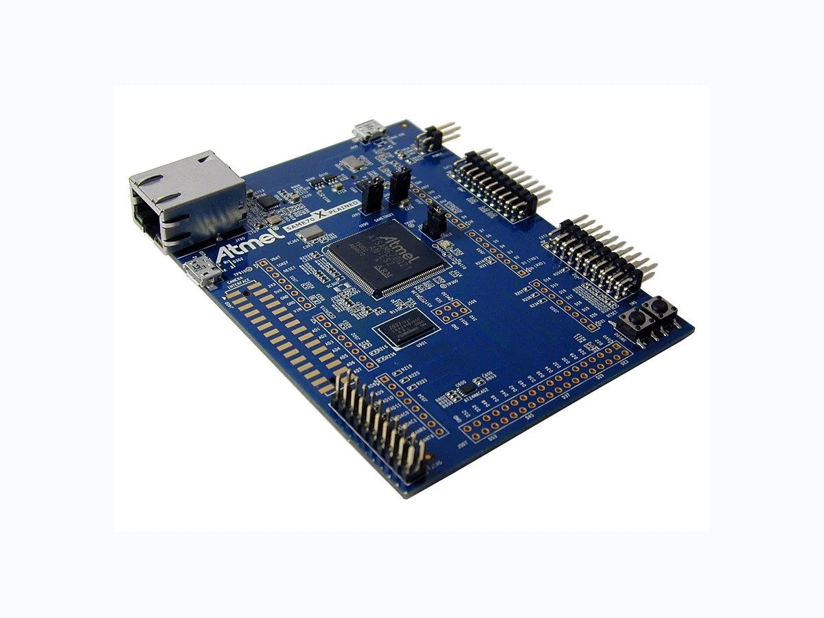
ATSAME70-XPLD ATMEL
Document overview
- Manufacturer or author: Provided By digicamel.com
- PDF pages: 58
Technical content
SMART ARM-based Microcontrollers SAME70-XPLD USER GUIDE Preface The Atmel SAM E70 Xplained evaluation kit is a hardware platform to evaluate the Atmel ATSAME70Q21 microcontroller. Supported by the Atmel Studio integrated development platform, the kit provides easy access to the features of the ATSAME70Q21 and explains how to integrate the device in a custom design. The Xplained Pro MCU series evaluation kits include an on-board Embedded Debugger, and no external tools are necessary to program or debug the ATSAME70Q21. The Xplained Pro extension series evaluation kits offers additional peripherals to extend the features of the board and ease the development of custom designs. Atmel-44050A-SAME70-XPLD_User Guide-12/2015
Atmel SAME70-XPLD [USER GUIDE] Atmel-44050A-SAME70-XPLD_User Guide-12/2015
- Introduction This user guide introduces the Atmel SAME70-XPLD evaluation kit and describes the development and debugging capabilities for applications running on a SAM E70 ARM-based embedded microcontroller. 1.1. Kit Contents
- Boards – One SAME70-XPLD board
- Cables – One Micro-AB type USB cable 1.2. Related Items
- Atmel SAM E70 Series Datasheet 1.3. Kit Overview 1.3.1. Evaluation Kit Architecture Figure 1-1 Evaluation Kit Architecture SDRAM 16Mb SDRAM ETHERNET Ethernet 10/100 InterfaceSDCARD 4-bit SDCARD Reader Interface USB DEBUG USB Micro A/B Connector ATMEL EDBG Atmel Embedded Debugguer JTAG 20-Pin JTAG Connector ARDUINO CONNECTORS 8-Expansion Headers Arduino R3 compatible PIO Signals (Not Populated) XPRO CONNECTORS 3-Expansions Headers Compatible with Atmel XPRO Extensions TARGET USB USB Micro A/B Connector CAMERA MODULE Camera Interface Connector for CAMx-EB Camera Module series (Not Populated) TRACE 20-pin debug connector For Trace (Not Populated) EEPROM I²C - 2k-bit serial EEprom And Unique 128-bit serial number AT24MAC402 Atmel SAME70-XPLD [USER GUIDE] Atmel-44050A-SAME70-XPLD_User Guide-12/2015
1.3.2. Evaluation Kit Specifications Table 1-1 Evaluation Kit Specifications Characteristic Specifications Temperature Operating 0°C to +70°C Storage -40°C to +85°C Relative Humidity 0 to 90% (non-condensing) RoHS status Compliant 1.3.3. Board Features Table 1-2 Board Specifications Characteristics Specifications PCB characteristics 83.5 × 105 × 16mm (4 layers) Processor ATSAME70Q21 (144-lead LQFP package) ARM Cortex-M7 Processor. Processor clock sources 12 MHz crystal oscillator 32.768 kHz crystal oscillator (not populated) EEPROM One AT24MAC402 EEPROM SDRAM One IS42S16100E 16 Mb SDRAM SD/MMC One 4-bit SD card connector USB One Micro-AB USB device One Micro-AB USB for EDBG debug interface Camera interface Camera Extension Header for connection with ISI Modules (not populated) Ethernet One Ethernet PHY (RMII 10/100) Debug port One JTAG interface connector One ETM Trace interface connector (not populated) Expansion connectors Three Atmel XPRO Extension Headers Arduino R3 compatible set of headers (not populated) GPIO,TWI, SPI, USART, UART and Audio interfaces are accessible via these headers Board supply voltage 5V from USB target, from USB Debug or from Arduino shield On-board power regulation is performed by a 3.3V LDO User interface Reset and free user pushbutton One green user LED 1.3.4. Board Overview The Atmel SAME70-XPLD is a hardware platform to evaluate the Atmel ATSAME70Q21. Atmel SAME70-XPLD [USER GUIDE] Atmel-44050A-SAME70-XPLD_User Guide-12/2015
It offers a set of features that enables the ATSAME70Q21 user to get started with the SAM V71, SAM V70, SAM E70 and SAM S70 peripherals right away and to get an understanding of how to integrate the device in their own design. The SAME70-XPLD board is equipped with the interface connectors described in Table 1-3. Table 1-3 SAME70-XPLD Board Interface Connectors Header Interfaces to J302 USB A device. Supports USB device using a Micro-AB connector J400 Camera Interface Connector (not populated) J401-J402 Atmel XPRO expansion connectors J403 Connector for Trace (not populated) (Footprint available on bottom side) J406 JTAG, 20-pin connector J500–J507 Expansion connectors with Arduino R3 compatible PIO signals (not populated) J600 SD/MMC connector (available on bottom side) J700 Ethernet ETH1 J900 Debug USB interface. Supports USB device using a Micro-AB connector. Interface used for target debug Figure 1-2 SAME70-XPLD Board Overview Atmel SAME70-XPLD [USER GUIDE] Atmel-44050A-SAME70-XPLD_User Guide-12/2015
- Getting Started 2.1. Xplained Pro Quick Start Three steps to start exploring the Atmel Xplained Pro platform: 1. Download Atmel Studio. 2. Launch Atmel Studio. 3. Connect a USB cable (Standard-A to Micro-B or Micro-AB) between the PC and the DEBUG USB port of the board. When the Atmel SAME70-XPLD is connected to your computer for the first time, the operating system will perform a driver software installation. The driver file supports both 32- and 64-bit versions of Microsoft Windows XP, Windows Vista , Windows 7, and Windows 8. Once the board is powered, Atmel Studio will auto detect which kind of MCU and extension board(s) are connected. Atmel Studio will present links to relevant information like datasheets and kit documentation. The kit landing page in Atmel Studio also has the option to launch Atmel Software Framework (ASF) example applications for the kit. The SAM E70 device is programmed and debugged by the on-board Embedded Debugger and therefore no external programmer or debugger tool is needed. 2.2. Design documentation and relevant links The following list contains links to the most relevant documents and software for SAME70-XPLD:
- Xplained Pro products - Atmel Xplained Pro is a series of small-sized and easy-to-use evaluation kits for Atmel microcontrollers and other Atmel products. It consists of a series of low-cost MCU boards for evaluation and demonstration of features and capabilities of different MCU families.
- Atmel Studio - Free Atmel IDE for development of C/C++ and assembler code for Atmel microcontrollers.
- Atmel sample store - Atmel sample store where you can order samples of devices.
- EDBG User Guide - User guide containing more information about the on-board Embedded Debugger.
- IAR Embedded Workbench for ARM - This is a commercial C/C++ compiler that is available for ARM . There is a 30 day evaluation version as well as a code size limited kick-start version available from their website. The code size limit is 16KB for devices with M0, M0+, and M1 cores and 32KB for devices with other cores.
- Atmel Data Visualizer - Atmel Data Visualizer is a program used for processing and visualizing data. Data Visualizer can receive data from various sources such as the Embedded Debugger Data Gateway Interface found on Xplained Pro boards and COM ports.
- Design Documentation - Package containing schematics, BOM, assembly drawings, 3D plots, layer plots etc.
- Hardware Users Guide in PDF format - PDF version of this User Guide. Atmel SAME70-XPLD [USER GUIDE] Atmel-44050A-SAME70-XPLD_User Guide-12/2015
- Xplained Pro Xplained Pro is an evaluation platform that provides the full Atmel microcontroller experience. The platform consists of a series of Microcontroller (MCU) boards and extension boards, which are integrated with Atmel Studio, have Atmel Software Framework (ASF) drivers and demo code, support data streaming, and more. Xplained Pro MCU boards support a wide range of Xplained Pro extension boards, which are connected through a set of standardized headers and connectors. Each extension board has an identification (ID) chip to uniquely identify which boards are connected to an Xplained Pro MCU board. This information is used to present relevant user guides, application notes, datasheets, and example code through Atmel Studio. 3.1. Embedded Debugger The SAME70-XPLD contains the Atmel Embedded Debugger (EDBG) for on-board debugging. The EDBG is a composite USB device of three interfaces: a debugger, Virtual COM Port, and a Data Gateway Interface (DGI). Together with Atmel Studio, the EDBG can program and debug the ATSAME70Q21. On the SAME70- XPLD, the SWD interface is connected between the EDBG and the ATSAME70Q21. The Virtual COM Port is connected to a UART on the ATSAME70Q21 and provides an easy way to communicate with the target application through terminal software. It offers variable baud rate, parity, and stop bit settings. Note that the settings on the ATSAME70Q21 must match the settings applied in the terminal software. Note: If not set automatically, data terminal ready (DTR) must be set in the terminal software. The DGI consists of several physical interfaces for communication with the host computer. Communication over the interfaces are bidirectional. It can be used to send events and values from the ATSAME70Q21 or as a generic printf-style data channel. Traffic over the interfaces can be timestamped on the EDBG for more accurate tracing of events. Note that timestamping imposes an overhead that reduces maximal throughput. Atmel Data Visualizer is used to send and receive data through DGI. For further documentation on the EDBG, see the EDBG User Guide. 3.2. Hardware Identification System All Xplained Pro compatible extension boards have an Atmel ATSHA204 CryptoAuthentication chip mounted. This chip contains information that identifies the extension with its name and some extra data. When an Xplained Pro extension is connected to an Xplained Pro MCU board the information is read and sent to Atmel Studio. The Atmel Kits extension, installed with Atmel Studio, will give relevant information, code examples, and links to relevant documents. The table below shows the data fields stored in the ID chip with example content. Table 3-1 Xplained Pro ID Chip Content Data field Data type Example content Manufacturer ASCII string Atmel'\\0' Product Name ASCII string Segment LCD1 Xplained Pro'\\0' Product Revision ASCII string 02'\\0' Product Serial Number ASCII string 1774020200000010’\\0’ Atmel SAME70-XPLD [USER GUIDE] Atmel-44050A-SAME70-XPLD_User Guide-12/2015
Data field Data type Example content Minimum Voltage [mV] uint16_t 3000 Maximum Voltage [mV] uint16_t 3600 Maximum Current [mA] uint16_t 30 3.3. Power Sources The SAME70-XPLD kit can be powered by several power sources listed in the table below. Warning: The 3.3V power domain is locally generated and must never be supplied from external sources or this would damage the on-board regulators. Table 3-2 SAME70-XPLD Power Sources Power input Voltage requirements Connector marking Embedded debugger USB 4.4V to 5.25V (USB spec.) DEBUG USB Target USB 4.4V to 5.25V (USB spec.) TARGET USB Arduino connector 5.0V typically J501 (pin 5) In case of USB power sources, the board automatically detects and switches to the available one. If the two are present (which is no problem whatsoever) the following priority applies: 1. Target USB (J302 connector) 2. Embedded Debugger USB (J900 connector) Info: USB sources supposedly provide a maximum current of 500mA. Calculate the power budget of your system, there is a possiblity this could be not enough if your SAME70-XPLD also connects to power demanding extension boards. The optional 5Vcc power source from the Arduino connector J501 is connected in parallel to the USB power switching system, hence the following warning: Warning: do not power the board form the Arduino shield (J501) when either of the two USB sources are connected. Doing so could damage the board and potentially also damage the USB port of your PC. 3.4. Xplained Pro Standard Extension Header All Xplained Pro kits have one or more dual row, 20-pin, 100mil extension header. Xplained Pro MCU boards have male headers, while Xplained Pro extensions have their female counterparts. Note that all pins are not always connected. All connected pins follow the defined pin-out description in the table below. Atmel SAME70-XPLD [USER GUIDE] Atmel-44050A-SAME70-XPLD_User Guide-12/2015
The extension headers can be used to connect a variety of Xplained Pro extensions to Xplained Pro MCU boards or to access the pins of the target MCU on Xplained Pro MCU boards directly. Table 3-3 Xplained Pro Standard Extension Header Pin number Name Description
1 ID Communication line to the ID chip on an extension board
2 GND Ground
3 ADC(+) Analog to digital converter, alternatively positive part of differential
4 ADC(-) Analog to digital converter, alternatively negative part of differential
5 GPIO1 General purpose I/O
6 GPIO2 General purpose I/O
7 PWM(+) Pulse width modulation, alternatively positive part of differential
8 PWM(-) Pulse width modulation, alternatively negative part of differential
9 IRQ/GPIO Interrupt request line and/or general purpose I/O
10 SPI_SS_B/
Slave select for SPI and/or general purpose I/O 11 I2C_SDA Data line for I2C interface. Always implemented, bus type. 12 I2C_SCL Clock line for I2C interface. Always implemented, bus type.
13 UART_RX Receiver line of target device UART
14 UART_TX Transmitter line of target device UART
15 SPI_SS_A Slave select for SPI. Should preferably be unique. 16 SPI_MOSI Master out slave in line of serial peripheral interface. Always implemented, bus type. 17 SPI_MISO Master in slave out line of serial peripheral interface. Always implemented, bus type. 18 SPI_SCK Clock for serial peripheral interface. Always implemented, bus type.
19 GND Ground
20 VCC Power for extension board
3.5. Xplained Pro Power Header The power header can only be used as supply for external peripherals or extension boards. Care must be taken not to exceed the total current limitation of the on-board regulator when using the 3.3V pin. Atmel SAME70-XPLD [USER GUIDE] Atmel-44050A-SAME70-XPLD_User Guide-12/2015
Table 3-4 Xplained Pro Power Header Pin number Pin name Description 1 n/a not connected
3 VCC_5V0 Output: unregulated 5V (output, derived from one of the input
sources) 4 VCC_3V3 Output: regulated 3.3V (output, used as main power supply for the kit) Atmel SAME70-XPLD [USER GUIDE] Atmel-44050A-SAME70-XPLD_User Guide-12/2015
- Hardware User Guide 4.1. Microcontroller The SAME70-XPLD board is built around the ATSAME70Q21 in a 144-lead LQFP package. It is a low- power ARM Cortex-M7 application microcontroller achieving high-performance computing device and embedding a wide range of communication peripherals. It features a combination of user interface functionalities and high data rate IOs, camera interface, 10/100 Ethernet ports, high-speed USB and SD Card. The ARM Cortex-M7 processor supports SDRAM memory through an EBI interface. An internal 150 MHz multi-layer AHB bus architecture associated with 24 XDMA channels, 384 Kbytes of SRAM and 2048 Kbytes of Flash sustains the high bandwidth required by the microcontroller and the high-speed peripherals. Figure 4-1 SAM E70 Block Diagram 12-layer Bus Matrix fMAX 150 MHz XDMA PCK0..2 XIN32 XOUT32 ERASE VDDCORE VDDIOVDDOUT Voltage Regulator TST WKUP0..13 VDDIO XIN XOUT VDDPLL RTCOUT0 RTCOUT1 S M M M M SS S S S M M M M M S System Controller S M In-Circuit Emulator MPU Cortex-M7 Processor fMAX300 MHz NVIC FPU TPIU ETM
16 Kbytes ICache + ECC 16 Kbytes DCache + ECC
TCK/SWCLKTDI TDO/TRACESWOJTAGSEL Serial Wire Debug/JTAG Boundary Scan TRACECLKTRACED0..3 TMS/SWDIO NRST PIOA/B/C/D/E 24-channel XDMA ROM Boot Program Multi-port SRAM Flash
2048 Kbytes
1024 Kbytes
512 Kbytes
Static Memory Controller (SMC) SDRAM Controller (SDRAMC) NAND Flash Logic QSPI XIP DMA ISI GMAC MII/RMII 5 x UART 3 x TWIHS 3 x USART 2 x PWM 2 x 12-bit AFE ACC 12-bit DACPIO SSC HSMCI 2 x SPI 4 x TC XDMA DMA Peripheral Bridge URXD0..4UTXD0..4 VREFN CANRX0..1CANTX0..1 ICM/SHA PIODCCLKPIODCEN1..2 PIODC0..7 TFTKTDRD RK RF MCDA0..3MCCDAMCCK SPIx_NPCS0..3 SPIx_MISOSPIx_MOSISPIx_SPCK PWMCx_PWMEXTRG0..1 AFEx_ADTRGAFEx_AD0..11 2 x MCAN DMA DMA Temp Sensor XDMAXDMAXDMAXDMAXDMAXDMAXDMAXDMAXDMA XDMA FIFO XDMA TRNGAES DMA VREFP Backup RAM
1 Kbyte
0–256 Kbytes 128–384 Kbytes 0–256 Kbytes PMC 4/8/12 MHz RC Oscillator RSTC SM POR SUPC RTT RTC WDT UPLL PLLA 3-20 MHz Crystal Oscillator 32 kHz Crystal Oscillator 32 kHz RC Oscillator Immediate Clear 256-bit SRAM (GPBR) Backup RSWDT 4.2. Power Distribution The SAME70-XPLD has two power sources as described in the figure Power Supply Block Diagram. The kit can be powered from the EDBG USB or from the target USB. The kit automatically selects a source to draw power. Priority is given to TARGET USB power input. Atmel SAME70-XPLD [USER GUIDE] Atmel-44050A-SAME70-XPLD_User Guide-12/2015
4.3.1. Extension Headers The Xplained Pro headers EXT1 and EXT2 on SAME70-XPLD give access to the I/O of the microcontroller in order to expand the system, e.g. by connecting extensions boards. The headers have a pitch of 2.54mm. Table 4-1 EXT1 Header EXT1 Pin SAM E70 Pin Function Shared Functionality 1 [ID ] -- ID_EXT1 Signal connected to Embedded Debugger 2 [GND] -- -- Ground Connection with Extension Board 3 [ADC(+)] PC31 AFE1_AD6 J502 Header & J504 Header (Arduino Shield) 4 [ADC(-)] PA19 AFE0_AD8 J502 Header (Arduino Shield) 5 [GPIO1] PB3 GPIO/RTS0 Camera Connector, EXT2 Header, J504 Header & J507 Header (Arduino Shield) 6 [GPIO2] PB2 GPIO/CTS0 EXT2 Header, J504 Header & J507 Header (Arduino Shield) 7 [PWM(+)] PA0 PWMC0_H0 -- 8 [PWM(-)] PC30 TIOB5 J502 Header (Arduino Shield) 9 [IRQ/GPIO] PD28 WKUP5 Camera Connector, Embedded Debugger, J503 Header & J505 Header (Arduino Shield) 10 [SPI_SS_B/GPIO] PC17 GPIO -- 11 [I2C_SDA] PA3 TWD0 Camera Connector, EXT2 Header, J500 Header (Arduino Shield), AT24MAC402, Embedded Debugger 12 [I2C_SCL] PA4 TWCK0 Camera Connector, EXT2 Header, J500 Header (Arduino Shield), AT24MAC402, Embedded Debugger 13 [UART_RX] PB0 RXD0 EXT2 Header, J505 Header & J507 Header (Arduino Shield) 14 [UART_TX] PB1 TXD0 EXT2 Header, J505 Header & J507 Header (Arduino Shield) 15 [SPI_SS_A] PD25 SPI0_NPCS1 Camera Connector, J500 Header (Arduino Shield) 16 [SPI_MOSI] PD21 SPI0_MOSI EXT2 Header, Camera Connector, J500 Header & J506 Header (Arduino Shield), Embedded Debugger 17 [SPI_MISO] PD20 SPI0_MISO EXT2 Header, J500 Header & J506 Header (Arduino Shield), Embedded Debugger 18 [SPI_SCK} PD22 SPI0_SPCK EXT2 Header, Camera Connector, J500 Header & J506 Header (Arduino Shield), Embedded Debugger Atmel SAME70-XPLD [USER GUIDE] Atmel-44050A-SAME70-XPLD_User Guide-12/2015
Function Shared Functionality 19 [GND] -- -- Ground Connection with Extension Board 20 [VCC] -- -- Power For Extension Board (3.3V only) Table 4-2 EXT2 Header EXT2 Pin SAM E70 Pin Function Shared Functionality 1 [ID ] -- ID_EXT2 Signal connected to Embedded Debugger 2 [GND] -- -- Ground Connection with Extension Board 3 [ADC(+)] PD30 AFE0_AD0 Camera Connector, J502 Header & J503 Header (Arduino Shield) 4 [ADC(-)] PC13 AFE1_AD1 J502 Header (Arduino Shield) 5 [GPIO1] PA6 GPIO Camera Connector, J503 Header (Arduino Shield) 6 [GPIO2] PD11 GPIO Camera Connector, J500 Header & J503 Header (Arduino Shield) 7 [PWM(+)] PC19 PWMC0_H2 Camera Connector, J503 Header (Arduino Shield) 8 [PWM(-)] PD26 PWMC0_L2 J502 Header (Arduino Shield) 9 [IRQ/GPIO] PA2 WKUP2 J503 Header (Arduino Shield), Embedded Debugger 10 [SPI_SS_B/ GPIO] PA24 GPIO Camera Connector, J507 Header (Arduino Shield) 11 [I2C_SDA] PA3 TWD0 Camera Connector, EXT1 Header, J500 Header (Arduino Shield), AT24MAC402, Embedded Debugger 12 [I2C_SCL] PA4 TWCK0 Camera Connector, EXT1 Header, J500 Header (Arduino Shield), AT24MAC402, Embedded Debugger 13 [UART_RX] PA21 RXD1 J507 Header (Arduino Shield), Embedded Debugger 14 [UART_TX] PB4 TXD1 J507 Header (Arduino Shield), Embedded Debugger Atmel SAME70-XPLD [USER GUIDE] Atmel-44050A-SAME70-XPLD_User Guide-12/2015
Function Shared Functionality 15 [SPI_SS_A] PB3 USART_SPI_NSS_MASTER_0 EXT1 Header, Camera Connector, J504 Header & J507 Header (Arduino Shield) PD31 USART_SPI_NSS_MASTER_0 Camera Connector PB2 USART_SPI_NSS_SLAVE EXT1 Header, J504 Header & J507 Header (Arduino Shield) PD27 SPI0_NPCS3 Camera Connector, J503 Header & J505 Header (Arduino Shield) 16 [SPI_MOSI] PD21 SPI0_MOSI EXT1 Header, Camera Connector, J500 Header & J506 Header (Arduino Shield), Embedded Debugger PB1 USART_SPI_MOSI EXT1 Header, J505 Header & J507 Header (Arduino Shield) 17 [SPI_MISO] PD20 SPI0_MISO EXT1 Header, J500 Header & J506 Header (Arduino Shield), Embedded Debugger PB0 USART_SPI_MOSI EXT1 Header, J505 Header & J507 Header (Arduino Shield) 18 [SPI_SCK} PD22 SPI0_SPCK EXT1 Header, Camera Connector, J500 Header & J506 Header (Arduino Shield), Embedded Debugger PB13 USART_SPI_SPCK J504 Header & J507 Header (Arduino Shield) 19 [GND] -- -- Ground Connection with Extension Board 20 [VCC] -- -- Power For Extension Board (3.3V only) 4.3.2. Arduino Connectors Five 8-pin, one 10-pin, one 2×3-pin and one 2×18-pin headers footprints (J500 to J507) are implemented on the board to enable the addition of "Arduino shields" extension cards. These accessory boards are various and widely available on the market, often custom developed. Due to the PIO multiplexing of the ATSAME70Q21, various peripheral signals may be connected to each pin. These connectors are mechanically (location and footprint) compatible with the Arduino R3 shields. Important: As the SAM E70 signals have a voltage level of 3.3V, 5V level shields cannot properly function with SAME70-XPLD. In addition to its standard IO functionality, the SAM E70 microcontroller can provide alternate functions to external IO lines available on the J500 to J507 headers. These alternate functions are: Atmel SAME70-XPLD [USER GUIDE] Atmel-44050A-SAME70-XPLD_User Guide-12/2015
- UARTs: UART1, UART2, UART3, UART4
- USARTs: USART0, USART1, USART2
- SPI: SPI0
- I²C: TWI0, TWI2
- Timer capture and compare: TIOA[0, 2,11], TIOB[5, 7, 8,11], TCLK[1, 2, 5, 8,11]
- Clock out: PCK0, PCK1, PCK2
- PWMs: PWMC0_PWMEXTRG[0,1], PWMC0_PWMH[0:3], PWMC_PWML[0, 2, 3], PWMC1_PWMEXTRG[0,1], PWMC1_PWMFI[0:2], PWMC1_PWMH[0, 2], PWMC1_PWML[0:3]
- DIGITAL AUDIO: TD, TK, TF, RD, RK, RF, GTSUCOMP
- CAN: CANRX0, CANTX0, CANRX1, CANTX1
- Analog: ADVREF, AFE0_AD[0, 6, 8], AFE1_AD[1, 3, 5, 6], DAC[0,1]
- GPIO: MISC
- RESET Refer to the SAM E70 Series datasheet for further details on the PIO multiplexing and alternate function selection. Caution: Like the Arduino Due, SAME70-XPLD runs at 3.3V and the maximum voltage that the I/O pins can tolerate is 3.3V, connecting higher voltages e.g. 5V to those I/O pin could damage the board. Important: not all pins of the shield connectors are necessarily connected to an I/O of the ATSAME70Q21. Each shield should be checked for compatibility against the SAME70-XPLD schematics before it is purchased and connected. 4.3.2.1. J500 Header J500 is a 10-pin header with 2.54mm pitch. It is not populated by default and can be used to connect to Arduino Shields. It includes PWM, Timer Counter and I2C interface signals and analog reference. Atmel SAME70-XPLD [USER GUIDE] Atmel-44050A-SAME70-XPLD_User Guide-12/2015
J406 - SAME 70 Debug (SWD) J600 - SDCAR D Socket (B ottom Side) J900 DE B UG USB Coresight 20 - SWD + ETM (B ottom Side) V DDCOR E V CC_MCU_3V 3 J200 - E R ASE J700 - E thernet R J45 J302 T arget USB CAME R A INTE R F A CE J501 - Power OPTION J502 - Analog L ow OPTION J504 - Analog High OPTION J506 - SPI OPTION OPTION J500 - Digital High OPTION J503 - Digital L ow OPTION J505 - Communication OPTION J507 - Digital E xtra OPTION J402 - E xtension Header 2 J401 - E xtension Header 1 J101 - Power Header Table 4-3 J500 Header IOs Pin PCB Marking PIO Primary Function Alternate Function
10 SCL PA4 TWCK0 TCLK0 UTXD1 WKUP3
9 SDA PA3 TWD0 PCK2 -- --
8 AREF ADVREF -- -- -- --
7 GND -- System
-- -- --
6 D13 PD22 SPI0_SPCK TIOB11 PWMC0_PWMH2 --
5 D12 PD20 SPI0_MISO GSTUCOMP PWMC0_PWMH0 --
4 D11 PD21 SPI0_MOSI TIOA11 PWMC0_PWMH1 --
PD11 GTSUCOMP PWMC0_PWMH0 -- --
3 D10 PD25 SPI0_NPCS1 URXD2 PWMC0PWML1 --
2 D9 PC9 TIOB7 -- -- --
1 D8 PA17 PWMC0_PW
AFE0_AD6 PCK1 -- Info: By default, pin 4 is connected to PD21 PIO through a 0R serial resistor. Alternately, it can be connected to PD11. To do so R210 must be removed and R212 must be mounted. Atmel SAME70-XPLD [USER GUIDE] Atmel-44050A-SAME70-XPLD_User Guide-12/2015
4.3.2.2. J501 Header J501 is a 8-pin header with 2.54mm pitch. It is not populated by default and can be used to connect to Arduino Shields. It allows power distribution (3.3V and 5V) to any Arduino Shield connected on the SAME70-XPLD board. Figure 4-5 J501 Header J406 - SAME 70 Debug (SWD) J600 - SDCAR D Socket (B ottom Side) J900 DE B UG USB Coresight 20 - SWD + ETM (B ottom Side) V DDCOR E V CC_MCU_3V 3 J200 - E R ASE J700 - E thernet R J45 J302 T arget USB CAME R A INTE R F A CE J501 - Power OPTION J502 - Analog L ow OPTION J504 - Analog High OPTION J506 - SPI OPTION OPTION J500 - Digital High OPTION J503 - Digital L ow OPTION J505 - Communication OPTION J507 - Digital E xtra OPTION J402 - E xtension Header 2 J401 - E xtension Header 1 J101 - Power Header Table 4-4 J501 Header IOs Pin PCB Marking Function 1 VBAT Not used on SAME70-XPLD board. Connected to testpoint TP910 2 IOREF ADVREF. Reference voltage for the analog inputs of the SAM E70 microcontroller. Actually connected to 3.3V.
3 RESET System reset
4 3V3 Main 3.3V supply - generated by the on-board regulator. 5 5V0 Main 5.0V supply (ouput or input). In case that pin is used as power supply source, do check the recommendations given in Power Sources on page 8 section.
6 GND System ground
7 GND System ground
8 VIN Not connected by default. Optional 5Vcc supply for any Arduino Shield. Info: Pin 8 is connected to the SAME70-XPLD board through an 0R serial resistor. It is necessary to mount 0R resistor R623 to enable the functionality. Atmel SAME70-XPLD [USER GUIDE] Atmel-44050A-SAME70-XPLD_User Guide-12/2015
4.3.2.3. J502 Header J502 is a 8-pin header with 2.54mm pitch. It is not populated by default and can be used to connect to Arduino Shields. It includes ADC inputs and a part of the Digital Audio Interface (TD). Figure 4-6 J502 Header J406 - SAME 70 Debug (SWD) J600 - SDCAR D Socket (B ottom Side) J900 DE B UG USB Coresight 20 - SWD + ETM (B ottom Side) V DDCOR E V CC_MCU_3V 3 J200 - E R ASE J700 - E thernet R J45 J302 T arget USB CAME R A INTE R F A CE J501 - Power OPTION J502 - Analog L ow OPTION J504 - Analog High OPTION J506 - SPI OPTION OPTION J500 - Digital High OPTION J503 - Digital L ow OPTION J505 - Communication OPTION J507 - Digital E xtra OPTION J402 - E xtension Header 2 J401 - E xtension Header 1 J101 - Power Header Table 4-5 J502 Header IOs Pin PCB Marking PIO Primary Function Alternate Function
1 AD0 PD26 TD UTXD2 UTXD1 PWMC0_PWML2
2 AD1 PC31 AFE1_AD6 TCLK5 -- --
3 AD2 PD30 AFE0_AD0 UTXD3 -- --
4 AD3 PA19 AFE0_AD8 PWMC0_PWML0 WKUP9 --
5 AD4 PC13 AFE1_AD1 PWMC0_PWMH3 -- --
6 AD5 PC30 AFE1_AD5 TIOB5 SPI1_NPCS3 --
7 AD6 PA17 AFE0_AD6 PWMC0_PWMH3 PCK1 --
8 AD7 PC12 AFE1_AD3 TIOB8 CANRX1 --
Info: Pins 6, 7, 8 are connected to SAM E70 PIOs through 0R serial resistors. It is necessary to mount them to enable the PIO functionality, respectively R214, R216, R236. Atmel SAME70-XPLD [USER GUIDE] Atmel-44050A-SAME70-XPLD_User Guide-12/2015
4.3.2.4. J503 Header J503 is a 8-pin header with 2.54mm pitch. It is not populated by default and can be used to connect to Arduino Shields. It includes PWM, Timer Counter, SPI Chip Select and UART3. Figure 4-7 J503 Header J406 - SAME 70 Debug (SWD) J600 - SDCAR D Socket (B ottom Side) J900 DE B UG USB Coresight 20 - SWD + ETM (B ottom Side) V DDCOR E V CC_MCU_3V 3 J200 - E R ASE J700 - E thernet R J45 J302 T arget USB CAME R A INTE R F A CE J501 - Power OPTION J502 - Analog L ow OPTION J504 - Analog High OPTION J506 - SPI OPTION OPTION J500 - Digital High OPTION J503 - Digital L ow OPTION J505 - Communication OPTION J507 - Digital E xtra OPTION J402 - E xtension Header 2 J401 - E xtension Header 1 J101 - Power Header Table 4-6 J503 Header IOs Pin PCB Marking PIO Primary Function Alternate Function
8 D7 PA2 PWMC0_PWMH1 WKUP2 --
7 D6 PC19 PWMC0_PWMH2 -- --
6 D5 PD11 PWMC0_PWMH0 -- --
5 D4 PD27 SPI0_NPCS3 PWMC0_PWML3 TWD2
4 D3 PA6 PCK0 UTXD1 --
PD10 PWMC0_PWML0 TD --
3 D2 PA5 PWMC1_PWML3 URXD1 WKUP4
(TXD) PD30 UTXD3 AFE0_AD0 -- 4 D0 (RXD) PD28 URXD3 TWCK2 CANRX1 Atmel SAME70-XPLD [USER GUIDE] Atmel-44050A-SAME70-XPLD_User Guide-12/2015
Info: By default, pin 4 is connected to SAM E70 PA6 PIO through a 0R serial resistor. Alternately, it can be connected to PD10. To do so, R217 must be removed and R218 must be mounted. 4.3.2.5. J504 Header J504 is a 8-pin header with 2.54mm pitch. It is not populated by default and can be used to connect to Arduino Shields. It includes ADC inputs, DAC outputs, CAN interface and Digital Audio Receive interface (RF, RD, RK). Figure 4-8 J504 Header J406 - SAME 70 Debug (SWD) J600 - SDCAR D Socket (B ottom Side) J900 DE B UG USB Coresight 20 - SWD + ETM (B ottom Side) V DDCOR E V CC_MCU_3V 3 J200 - E R ASE J700 - E thernet R J45 J302 T arget USB CAME R A INTE R F A CE J501 - Power OPTION J502 - Analog L ow OPTION J504 - Analog High OPTION J506 - SPI OPTION OPTION J500 - Digital High OPTION J503 - Digital L ow OPTION J505 - Communication OPTION J507 - Digital E xtra OPTION J402 - E xtension Header 2 J401 - E xtension Header 1 J101 - Power Header Table 4-7 J504 Header IO Pin PCB Marking PIO Primary Function Alternate Function
1 AD8 PD24 RF TCLK11 PWMC0_PWML0 -- --
2 AD9 PA10 RD PWMC0_PWMEXTRG
-- -- --
3 AD10 PA22 RK PWMC0_PWMEXTRG
-- -- --
4 AD11 PC31 AFE1_AD6 TCLK5 -- -- --
5 DAC0 PB13 DAC0 PWMC0_PWML2 PCK0 -- --
6 DAC1 PD0 DAC1 PWMC1_PWML0 SPI1_NPCS1 -- --
7 CANRX PB3 CANRX0 RTS0 PCK2 AFE0_AD2 WKUP12
8 CANTX PB2 CANTX0 AFE0_AD5 SPI0_NPCS0 CTS0 --
Atmel SAME70-XPLD [USER GUIDE] Atmel-44050A-SAME70-XPLD_User Guide-12/2015
4.3.2.6. J505 Header J505 is a 8-pin header with 2.54mm pitch. It is not populated by default and can be used to connect to Arduino Shields. It includes UART0, UART2, UART4 and TWI interfaces. Figure 4-9 J505 Header J406 - SAME 70 Debug (SWD) J600 - SDCAR D Socket (B ottom Side) J900 DE B UG USB Coresight 20 - SWD + ETM (B ottom Side) V DDCOR E V CC_MCU_3V 3 J200 - E R ASE J700 - E thernet R J45 J302 T arget USB CAME R A INTE R F A CE J501 - Power OPTION J502 - Analog L ow OPTION J504 - Analog High OPTION J506 - SPI OPTION OPTION J500 - Digital High OPTION J503 - Digital L ow OPTION J505 - Communication OPTION J507 - Digital E xtra OPTION J402 - E xtension Header 2 J401 - E xtension Header 1 J101 - Power Header Table 4-8 J505 Header IOs Pin PCB Marking PIO Primary Function Alternate Function
8 D14 PB1 TXD0 TK GTSUCOMP PWMC0_PWMH1 AFE1_AD0
7 D15 PB0 RXD0 TF PWMC0_PWMH0 AFE0_AD10 --
4 D18 PD19 UTXD4 CTS2 -- -- --
3 D19 PD18 URXD4 RTS2 -- -- --
2 D20 PD27 TWD2 SPI0_NPCS3 PWMC0_PWML3 -- --
1 D21 PD28 TWCK2 CANRX1 URXD3 WKUP5 --
4.3.2.7. J506 Header J506 is a 2x3-pin header with 2.54mm pitch. It is not populated by default and can be used to connect to Arduino Shields. It includes the SPI interface. Atmel SAME70-XPLD [USER GUIDE] Atmel-44050A-SAME70-XPLD_User Guide-12/2015
J406 - SAME 70 Debug (SWD) J600 - SDCAR D Socket (B ottom Side) J900 DE B UG USB Coresight 20 - SWD + ETM (B ottom Side) V DDCOR E V CC_MCU_3V 3 J200 - E R ASE J700 - E thernet R J45 J302 T arget USB CAME R A INTE R F A CE J501 - Power OPTION J502 - Analog L ow OPTION J504 - Analog High OPTION J506 - SPI OPTION OPTION J500 - Digital High OPTION J503 - Digital L ow OPTION J505 - Communication OPTION J507 - Digital E xtra OPTION J402 - E xtension Header 2 J401 - E xtension Header 1 J101 - Power Header Table 4-9 J506 Header IOs Pin PCB Marking PIO Primary Function
1 MISO PD20 SPI0_MISO
3 SPCK PD22 SPI0_SPCK
4 MOSI PD21 SPI0_MOSI
5 RST NRST System reset
6 GND -- System ground
4.3.2.8. J507 Header J507 is a 2x18-pin header with 2.54mm pitch. It is not populated by default and can be used to connect to Arduino Shields. It includes PWM, Timer Counters, Audio Transmit interface, CAN interface, USART1 and USART2 interfaces and four UART interfaces. Atmel SAME70-XPLD [USER GUIDE] Atmel-44050A-SAME70-XPLD_User Guide-12/2015
J406 - SAME 70 Debug (SWD) J600 - SDCAR D Socket (B ottom Side) J900 DE B UG USB Coresight 20 - SWD + ETM (B ottom Side) V DDCOR E V CC_MCU_3V 3 J200 - E R ASE J700 - E thernet R J45 J302 T arget USB CAME R A INTE R F A CE J501 - Power OPTION J502 - Analog L ow OPTION J504 - Analog High OPTION J506 - SPI OPTION OPTION J500 - Digital High OPTION J503 - Digital L ow OPTION J505 - Communication OPTION J507 - Digital E xtra OPTION J402 - E xtension Header 2 J401 - E xtension Header 1 J101 - Power Header Table 4-10 J507 Header IOs Pin PCB Marking PIO Primary Function Alternate Function 1 5V0 -- Power supply -- -- -- 2 5V0 -- Power supply -- -- --
3 D22 PA18 PCK2 PWMC1_PWMEXTR
-- --
4 D23 PB1 TK PWMC0_PWMH1 AFE1_AD0 GTSUCOMP
5 D24 PB0 TF PWMC0_PWMH0 AFE0_AD10 RXD0
6 D25 PD17 SCK2 -- -- --
7 D26 PD19 CTS2 UTXD4 -- --
8 D27 PD18 RTS2 URXD4 -- --
9 D28 PA5 PWMC1_PWML3 URXD1 WKUP4 --
10 D29 Not Connected
11 D30 PA29 TCLK2 -- -- --
12 D31 PA1 WKUP1 PWMC0_PWML0 TIOB0 --
13 D32 Not Connected
14 D33 PA26 PWMC1_PWMFI1 TIOA2 -- --
15 D34 Not Connected
Atmel SAME70-XPLD [USER GUIDE] Atmel-44050A-SAME70-XPLD_User Guide-12/2015
PIO Primary Function Alternate Function
16 D35 PA12 PWMC1_PWMH0 PWMC0_PWMH1 -- --
17 D36 PA13 PWMC1_PWML1 PWMC0_PWMH2 -- --
18 D37 Not Connected
19 D38 PB13 SCK0 PWMC0_PWML2 DAC0 PCK0
20 D39 PB2 CTS0 SPI0_NPCS0 CANTX0 AFE0_AD5
21 D40 PB3 RTS0 PCK2 CANRX0 AFE0_AD2
22 D41 PA31 PWMC1_PWMH2 PCK2 SPI0_NPCS1 --
23 D42 Not Connected
24 D43 PA23 PWMC0_PWMH0 PWMC1_PWML2 SCK1 --
25 D44 PA25 CTS1 PWMC0_PWMH2 -- --
26 D45 PA24 RTS1 PWMC0_PWMH1 -- --
27 D46 PA21 RXD1 PWMC1_PWMFI0 AFE0_AD1 PCK1
28 D47 PB4 TXD1 PWMC0_PWMH2 TWD1 --
29 D48 PA30 PWMC1_PWMEXTR
PWMC0_PWML2 WKUP11 --
30 D49 PA28 PWMC1_PWMFI2 TCLK1 -- --
31 D50 PA18 PWMC1_PWMEXTR
32 D51 Not Connected
33 D52 PC12 CANRX1 AFE1_AD3 TIOB8 --
34 D53 PC14 CANTX1 TCLK8 -- --
35 GND -- System ground -- -- --
36 GND -- System ground -- -- --
4.3.3. Camera Connector A 2×15-pin, 100mil pin-header camera connector is implemented to give access to the SAM E70 parallel Image Sensor Interface (ISI). Atmel SAME70-XPLD [USER GUIDE] Atmel-44050A-SAME70-XPLD_User Guide-12/2015
Figure 4-12 Camera Connector J406 - SAME 70 Debug (SWD) J600 - SDCAR D Socket (B ottom Side) J900 DE B UG USB Coresight 20 - SWD + ETM (B ottom Side) V DDCOR E V CC_MCU_3V 3 J200 - E R ASE J700 - E thernet R J45 J302 T arget USB CAME R A INTE R F A CE J501 - Power OPTION J502 - Analog L ow OPTION J504 - Analog High OPTION J506 - SPI OPTION OPTION J500 - Digital High OPTION J503 - Digital L ow OPTION J505 - Communication OPTION J507 - Digital E xtra OPTION J402 - E xtension Header 2 J401 - E xtension Header 1 J101 - Power Header Table 4-11 J400 - Camera Connector Pin Number SAM E70 Pin Function Shared Functionality 2 - 4 -- GND --
5 PA13 ISI_RST J507 Header (Arduino Shield)
6 PC19 ISI_PWD EXT2 Header, J503 Header (Arduino Shield)
7 PA4 TWCK0 EXT1 Header, EXT2 Header, AT24MAC402, J500 Header
(Arduino Shield), Embedded Debugger
8 PA3 TWD0 EXT1 Header, EXT2 Header, J503 Header, J500 Header
(Arduino Shield), Embedded Debugger 9 -- GND --
10 PA6 PCK0 EXT2 Header, J503 Header (Arduino Shield)
12 PD25 ISI_VSYNC EXT1 Header, J500 Header (Arduino Shield)
14 PD24 ISI_HSYNC J504 Header (Arduino Shield)
16 PA24 ISI_PCK EXT2 Header, J507 Header (Arduino Shield)
Atmel SAME70-XPLD [USER GUIDE] Atmel-44050A-SAME70-XPLD_User Guide-12/2015
Pin Number SAM E70 Pin Function Shared Functionality
18 PD22 ISI_D0 EXT1 Header, EXT2 Header, J500 Header & J506 Header
(Arduino Shield), Embedded Debugger
19 PD21 ISI_D1 EXT1 Header, EXT2 Header, J500 Header & J506 Header
(Arduino Shield), Embedded Debugger
20 PB3 ISI_D2 EXT1 Header, EXT2 Header, J504 Header & J507 Header
(Arduino Shield)
21 PA9 ISI_D3 Embedded Debugger
22 PA5 ISI_D4 J503 Header & J507 Header (Arduino Shield)
23 PD11 ISI_D5 EXT2 Header, J500 Header & J503 Header (Arduino Shield)
24 PD12 ISI_D6 Embedded Debugger
25 PA27 ISI_D7 SD Card
26 PD27 ISI_D8 EXT2 Header, J503 Header & J505 Header (Arduino Shield)
27 PD28 ISI_D9 EXT1 Header, J503 Header & J505 Header (Arduino Shield),
28 PD30 ISI_D10 EXT2 Header, J502 Header & J503 Header (Arduino Shield)
29 PD31 ISI_D11 EXT2 Header
4.3.4. USB The SAME70-XPLD board features a Micro-USB connector that implements the SAM E70 USB high speed interface. This connector is labeled as TARGET USB on the board. Figure 4-13 USB Interface Schematic ATMEL SAME70 VCC_USB C219 10pF 5V D- D+ ID G MICRO USB AB 5 J302 R233 5.62K D302 PRTR5V0U2X DNP HSDP 137 HSDM 136 VBG 140 Table 4-12 USB Interface Signal Descriptions J302 Pin Mnemonic Pin on SAM E70 SAM E70 Signal Name Signal Description
1 VBUS -- -- 5V power
2 DM 136 HSDM Data minus
3 DP 137 HSDP Data plus
Atmel SAME70-XPLD [USER GUIDE] Atmel-44050A-SAME70-XPLD_User Guide-12/2015
J302 Pin Mnemonic Pin on SAM E70 SAM E70 Signal Name Signal Description
4 ID -- -- On-the-go identification
5 Ground GND GND System Ground
4.3.5. Current Measurement Header (VCC_MCU_P3V3 ) A 100mil pin-header marked "J203" is located at the upper edge of the SAME70-XPLD. All the power going to the ATSAME70Q21 is routed through this header. To measure the power consumption of the device, remove the jumper and replace it with an ammeter. Figure 4-14 VCC_MCU_P3V3 Connector Placement J203 J203 Caution: Removing the jumper from the pin-header while the board is connected to otherwise powered extension boards or systems may cause the ATSAME70Q21 to be powered through its I/O pins. This could cause permanent damage to the device. 4.3.6. VDDCORE Current Measurement A 100mil pin-header marked "J201" is located at the upper edge of the SAME70-XPLD board. It is not mounted by default and is replaced by a shunt trace between the two pads of the connector. All power to VDDCORE of the ATSAME70Q21 is routed through this header. To measure the power consumption of VDDCORE, cut the shunt trace between the two points, mount a header or solder wires and connect an ammeter. Figure 4-15 VDDCORE Connector Placement J201 J201 Atmel SAME70-XPLD [USER GUIDE] Atmel-44050A-SAME70-XPLD_User Guide-12/2015
Table 4-13 CoreSight 20-Pin Trace Connector Pin Number SAM E70 Pin Function Shared With 1-[VTREF] - VCC_3V3 -- 2-[SWDIO] PB6 SWDIO Embedded Debugger 3-5-9-15-17-19[GND] - System Ground -- 4-[SWCLK] PB7 SWCLK Embedded Debugger 6-[TRACESWO] PB5 TRACESWO Embedded Debugger 7-[KEY] - - -- 8-11-13[NC] - - -- 10-[nSRST] NRST NRST Arduino Connectors and Embedded Debugger 12-[TRACECLK] PD8 TRACECLK Ethernet 14-[TRACED0] PD4 TRACED0 Ethernet 16-[TRACED1] PD5 TRACED1 Ethernet 18-[TRACED2] PD6 TRACED2 Ethernet 20-[TRACED3] PD7 TRACED3 Ethernet 4.4. Peripherals 4.4.1. Clock Circuitry The SAME70-XPLD board features three clock sources:
- Two crystals for the ATSAME70Q21 processor
- One crystal oscillator for the Ethernet MII/RMII chip The crystals of the ATSAME70Q21 have cut-straps next to them that can be used to measure the oscillator safety factor. This is done by cutting the strap and adding a resistor across the strap. Information about oscillator allowance and safety factor can be found in the application note AVR4100; information about clock calibration and compensation can be found in the application note AT03155. Table 4-14 Main Components Associated with the Clock Systems Quantity Description Component Assignment
1 Crystal for internal clock, 12 MHz XC301
1 Crystal for RTC clock, 32.768 kHz (Not Populated) XC300
1 Oscillator for Ethernet clock RMII, 25 MHz XC700
Table 4-15 External Crystals Connected on SAM E70 SAM E70 pin Function 32.768 kHz External Crystal Connection (Not Populated by default) PA7 XIN32: Slow Clock Oscillator Input Atmel SAME70-XPLD [USER GUIDE] Atmel-44050A-SAME70-XPLD_User Guide-12/2015
PA8 XOUT32: Slow Clock Oscillator Output
12 MHz External Crystal Connection
PB9 XIN: Main Oscillator Input PB8 XOUT: Main Oscillator Output Figure 4-19 SAM E70 Crystals Schematic SAME70 XIN XOUT C302 12pF C303 12pF XC301 12MHz PB8 141 PB9 142 J301 1 2 PA8 PA7 XOUT32 XIN32 PA8 J300 C301 18pF DNP 36 XC300 32.768 kHz DNP C300 18pF DNP PA7 4.4.2. Mechanical Buttons Two pushbutton switches are available. When a button is pressed, it drives the corresponding I/O line to GND.
- One board reset button (SW100). When pressed and released, this pushbutton causes a power-on reset of the whole board.
- One wakeup pushbutton that brings the processor out of Low-power mode (SW300) Figure 4-20 Mechanical Button Schematic VCC_3V3 EDBG_TARGET_RESET TARGET_RESET_SENSE TARGET_RESE T R110 39R C104 10nF R122 TP100 SW100 R107 330R R106 100K SAME70 USER BUTTON WKUP6 PA11 R300 39R PA11 TP300 SW300 Important: There is no pull-up resistor connected to SW300 button. Remember to enable the internal pull-up in the SAM E70 to use the button. 4.4.3. LEDs There is one green LED mounted on the SAME70-XPLD. It can be activated by driving the connected I/O line to a low level. Figure 4-21 LED Indicators Schematic USER LED LED0 PC8 VCC_3V3 R303 330R D301 Gree n Atmel SAME70-XPLD [USER GUIDE] Atmel-44050A-SAME70-XPLD_User Guide-12/2015
SAM E70 Pin Function Shared With PC8 Green LED -- 4.4.4. SDRAM The SAME70-XPLD features one IS42S16100F-5BL, 512K×16×2, 10ns, SDRAM chip. The SDRAM is connected to chip select NCS1. SDRAM access can be configured in the SDRAM Controller in the SAM E70. Table 4-17 SDRAM Connections on page 32 lists all I/O lines connected to the SDRAM. Figure 4-22 SDRAM Schematic D10 D11 D12 D13 D14 D15 A10 A11 SDA10 BA0 SDCK SDCKE SDCS RAS CAS SDWE A0/NBS0 NWR1/NBS1 VCC_3V3 VCC_3V3 VCC_3V3 PC0 PC1 PC2 PC3 PC4 PC5 PC6 PC7 PE0 PE1 PE2 PE3 PE4 PE5 PA15 PA16 PC20 PC21 PC22 PC23 PC24 PC25 PC26 PC27 PC28 PC29 PD13 PA20 PD23 PD14 PC15 PD16 PD17 PD29 PC18 PD15 R137 22R R115 22R R617 100K C908 2.2uF R128 22R R119 22R R132 22R R124 22R C922 100nF R136 22R R140 22R R114 22R R127 22R R118 22R C918 100nF R125 22R R131 22R R123 22R R111 22R C921 100nF R135 22R R139 22R R113 22R R126 22R R117 22R C917 100nF R130 22R R121 22R C920 100nF R134 22R R138 22R R112 22R R116 22R C919 100nF C916 100nF U901 IS42S16100F-5BL A10 A11 DQ0 DQ1 DQ2 DQ3 DQ4 DQ5 DQ6 DQ7 DQ8 DQ9 DQ10 DQ11 DQ12 DQ13 DQ14 DQ15 A2CLK CKE CS RAS CAS WE LDQM UDQM VDD2 VDD3 VDD1 VSS1 VSS2 VSSQ4 F6VSSQ3 E2VSSQ2 C6VSSQ1 VDDQ4 F2VDDQ3 E6VDDQ2 C2VDDQ1 NC1 NC2 NC3 NC4 NC5 NC7 NC8 NC9 NC10 NC11 NC6 R129 22R R120 22R R133 22R Table 4-17 SDRAM Connections SAM E70 Pin Function SDRAM Function Shared With PC0 D0 Data line 0 – PC1 D1 Data line 1 – PC2 D2 Data line 2 – PC3 D3 Data line 3 – PC4 D4 Data line 4 – PC5 D5 Data line 5 – PC6 D6 Data line 6 – PC7 D7 Data line 7 – PE0 D8 Data line 8 – PE1 D9 Data line 9 – PE2 D10 Data line 10 – PE3 D11 Data line 11 – PE4 D12 Data line 12 – PE5 D13 Data line 13 – Atmel SAME70-XPLD [USER GUIDE] Atmel-44050A-SAME70-XPLD_User Guide-12/2015
SAM E70 Pin Function SDRAM Function Shared With PA15 D14 Data line 14 – PA16 D15 Data line 15 – PC20 A2 Address line 0 – PC21 A3 Address line 1 – PC22 A4 Address line 2 – PC23 A5 Address line 3 – PC24 A6 Address line 4 – PC25 A7 Address line 5 – PC26 A8 Address line 6 – PC27 A9 Address line 7 – PC28 A10 Address line 8 – PC29 A11 Address line 9 – PD13 SDA10 Address line 10 – PA20 BA0 Bank select line 0 – PD23 SDCK Clock – PD14 SDCKE Clock Enable – PC15 SDCS Chip Select – PD16 RAS RAS Shield J505 Header (Arduino Shield) PD17 CAS CAS J507 Header (Arduino Shield) PD29 SDWE Write Enable – PC18 A0/NBS0 LDQM – PD15 NWR1/NBS1 UDQM J505 Header (Arduino Shield) 4.4.5. SD Card The SAME70-XPLD has one standard SD card slot, connected to the High-speed Multimedia Card Interface (HSMCI) of the SAM E70. Table 4-18 SD/MMC Socket J600 Signal Descriptions on page 34 lists all I/O lines connected to the SD card connector. Figure 4-23 SD/MMC Socket J600 Schematic SD_WP SD_D0 SD_D1 SD_D2 SD_D3 SD_CLK SD_DETECT SD_CMD VCC_3V3 VCC_3V3 PA30 PA31 PA26 PA27 PA28 PA25 PC16 R607 100K J901 J600 SD Card SOCKET DAT0 DAT1 DAT2 DAT3 VDD VSS1 VSS2 SHELL CLK CMD C/D W/P SHELL SHELL SHELL R606 10K R610 100K R612 10K R609 100K R611 10K TP600 C613 100nF R608 100K C612 10uF Atmel SAME70-XPLD [USER GUIDE] Atmel-44050A-SAME70-XPLD_User Guide-12/2015
Table 4-18 SD/MMC Socket J600 Signal Descriptions Pin Mnemonic SAM E70 Pin Signal Description Shared WIth
1 DAT3 PA27 Data bit (MCDA3) Camera Connector
2 CMD PA28 Command line (MCCDA) J507 Header (Arduino Shield)
3 VSS -- Common ground --
4 VCC -- Supply voltage 3.3V --
5 CLK PA25 Clock / command line (MCCK) J507 Header (Arduino Shield)
6 VSS -- Common ground --
7 DAT0 PA30 Data bit (MCDA0) J507 Header (Arduino Shield)
8 DAT1 PA31 Data bit (MCDA1) J507 Header (Arduino Shield)
9 DAT2 PA26 Data bit (MCDA2) J507 Header (Arduino Shield)
10 C/D PC16 Card Detect --
11 WP -- Protect --
12 SHELL -- Connected to Ground --
13 SHELL -- Connected to Ground --
14 SHELL -- Connected to Ground --
15 SHELL -- Connected to Ground --
4.4.6. Ethernet The ATSAME70Q21 has a built-in 10/100 Mbps Ethernet IEEE 802.3 compatible MAC with RMII interface. The SAME70-XPLD connects the MAC to a Micrel KSZ8081RNACA RMII physical-layer transceiver (PHY), which is connected to one RJ45 Ethernet connector. A unique EUI-48™ address is available on every SAME70-XPLD through the on-board AT24MAC402, the EUI-48 address can be used as a MAC address for the KSZ8081RNACA. The address is also programmed into the on-board EDBG. Table 4-19 KSZ8081RNACA Connections on page 35 lists all pins connected from the SAM E70 to the Ethernet PHY. Info: Several of the Ethernet signals are shared with the trace connector and thus there is no Ethernet support if trace is used in an application. Atmel SAME70-XPLD [USER GUIDE] Atmel-44050A-SAME70-XPLD_User Guide-12/2015
Figure 4-24 RMII Ethernet Schematic PHY_RESET PHY_INTERRUPT PHY_MDC PHY_MDIO PHY_CRS_DV PHY_TXEN PHY_TXD0 PHY_TXD1 PHY_RXER PHY_RXD0 PHY_RXD1PHY_REFCLK PHY_MDIO PHY_RXD1 PHY_RXD0 PHY_CRS_DV PHY_MDC RMII_XTALO RMII_XTALI VDDPLL_1.2V VDDA_ENET VCC_3V3 VCC_3V3 VCC_3V3 VCC_3V3 VCC_3V3 PD0 PD1 PD2 PD3 PD5 PD6 PD4 PD7 PC10 PA14 PD8 PD9 PD8 PD5 PD6 PD9 PD4 KSZ8081RNACA U700 VDD_1V2 VDDA_3V3 RXM 3RXP TXM 5TXP XO XI REXT MDIO MDC RXD1 12RXD0 VDDIO CRS_RV/PHYAD1/PHYAD0 REF_CLK RXER INTRP TXEN TXD0 TXD1 GND1 LED0/ANEN_SPEED 23RST GND2 R56 1.5K C704 24PF R238 39R C708 2.2uF R702 10K C709 24PF C700 100nF L700 C711 100nF R67 10K DNP C702 100nF C220 10uF R704 6.49K R69 10K DNP R70 10K C92 100PF DNP C713 10uF C710 100nF R906 R71 10K DN P XC700 25MHZ 1 4 R55 1.5K DNP C701 4.7uF PHY_TXP PHY_TXM PHY_RXP PHY_RXM LED0_SPEED Figure 4-25 Ethernet RJ45 Schematic LED1_LINK VCC_3V3 VCC_3V3 R70 3 470 C706 100nF R701 470 L701 TD+_R1 TD-_R2 TCT_R3 RD+_R7 1000pF Y
75 OHMS
1 : 1 NC_4 C6_RX- C3_RX+ C2_TX- C1_TX+ NC_5 1 : 1
75 OHMS 75 OHMS
G RD-_R8 RCT_R6 J700 RJ45 C705 100nF PHY_TXP PHY_TXM PHY_RXP PHY_RXM LED0_SPEED VCC_3V3 R604 10K Table 4-19 KSZ8081RNACA Connections SAM E70 Pin Exthernet Function Shared With PD0 PHY_REFCLK J504 Header (Arduino Shield) PD1 PHY_TXEN – PD2 PHY_TXD0 – PD3 PHY_TXD1 – PD4 PHY_CRS_DV Trace Connector PD5 PHY_RXD0 Trace Connector PD6 PHY_RXD1 Trace Connector Atmel SAME70-XPLD [USER GUIDE] Atmel-44050A-SAME70-XPLD_User Guide-12/2015
SAM E70 Pin Exthernet Function Shared With PD7 PHY_RXER Trace Connector PD8 PHY_MDC Trace Connector PD9 PHY_MDIO – PC10 PHY_RESET – PA14 PHY_INTERRUPT – The KSZ8081RNACA also has a set of parameters that are latched in during reset based on I/O pin levels. These configuration options have a default mode on the kit done by external pull-up and pull-down resistors. For detailed information about the configuration, refer to the KSZ8081RNACA datasheet. Table 4-20 KSZ8081RNACA Configuration Configuration Name Default Value on Kit Default Configuration PHYAD 0x0h The PHYs address is 0x0h. It can be set to 0x3h if R70 and R71 are permutted. AUTONEG Pull-Up Auto negotiation enabled and set 100Mbps speed 4.4.7. AT24MAC402 The SAME70-XPLD features one Atmel AT24MAC402 serial EEPROM with an EIA-48 MAC address connected to the SAM E70 through I2C. This AT24MAC402 is configured on the I2C interface with the address 0x37h. It contains a MAC address for use with the Ethernet interface. Table 4-21 AT24MAC402 Connections on page 36 lists all I/O lines connected to the AT24MAC402 device. Figure 4-26 AT24MAC402 Schematic MAC24_A0 MAC24_A1 MAC24_A2 TWD0 TWCK0 VCC_3V3 VCC_3V3 PA3 PA4 PC11 R603 10K U600 AT24MAC402-MAHM-T GND SDA SCL WP VCC R600 10K R601 10K R602 10K C600 100n F Table 4-21 AT24MAC402 Connections SAM E70 Pin Function AT24MAC402 Function Shared With PA3 TWD0 SDA (Serial Data Line) Camera Connector, EXT1 Header, EXT2 Header, J500 Header (Arduino Shield), Embedded Debugger PA4 TWCK0 SCL (Serial Click Line) Camera Connector, EXT1 Header, EXT2 Header, J500 Header (Arduino Shield), Embedded Debugger PC11 GPIO WP (Write Protect) -- Atmel SAME70-XPLD [USER GUIDE] Atmel-44050A-SAME70-XPLD_User Guide-12/2015
4.4.8. Debug JTAG/ICE A 2×10-pin JTAG header is implemented on the SAME70-XPLD board to enable software development and debugging of the board by using various JTAG emulators. The interface signals have a voltage level of 3.3V. Figure 4-27 JTAG/ICE Interface Schematic ARM JTAG SWDIO SWCLK TRACESWO VCC_3V3 PB6 PB7 PB5 TARGET_RESET R401 R402 R403 J406 6 5 910 1112 1314 1516 1718 1920 R400 Table 4-22 JTAG/ICE Connector J406 Signal Descriptions Pin Signal Type Signal Description
1 VTref /
VCC_3V3 Input This is the target reference voltage. It is used to check if the target has power, to create the logic- level reference for the input comparators and to control the output logic levels to the target. It is normally fed from Vdd of the target board and must not have a series resistor.
2 Vsupply /
VCC_3V3 Not Used This pin is not connected in J-Link. It is reserved for compatibility with other equipment. Connect to Vdd or leave open in target system. 3 Not used NC This pin is not used by J-Link. If the device may also be accessed via JTAG, this pin may be connected to nTRST, otherwise leave open. 5 Not used NC This pin is not used by J-Link. If the device may also be accessed via JTAG, this pin may be connected to TDI, otherwise leave open. 7 SWDIO I/O Single bi-directional data pin. 9 SWCLK Output Clock signal to target CPU. It is recommended that this pin is pulled to a defined state of the target board. Typically connected to TCK of target CPU. 11 Not used NC This pin is not used by J-Link. This pin is not used by J-Link when operating in SWD mode. If the device may also be accessed via JTAG, this pin may be connected to RTCK, otherwise leave open. 13 SWO Output Serial Wire Output trace port. (Optional, not required for SWD communication.) 15 RESET I/O Target CPU reset signal. Typically connected to the RESET pin of the target CPU, which is typically called "nRST", "nRESET" or "RESET". 17 Not used NC This pin is not connected in J-Link. Atmel SAME70-XPLD [USER GUIDE] Atmel-44050A-SAME70-XPLD_User Guide-12/2015
Pin Signal Type Signal Description
19 Not Used
(5V-Supply) Output This pin is used to supply power to some eval boards. Not all JLinks supply power on this pin, only the KS (Kickstart) versions. Typically left open on target hardware. 4-6-8-10-12-14-16-18-20 GND -- System Ground 4.5. Zero Ohm Resistors The SAME70-XPLD has several zero ohm resistors that can be used to disconnect I/O pins of the ATSAME70Q21 from connectors and on-board ICs and to disconnect power signals. All Arduino pin numbers are listed in Arduino Connectors. The table Zero Ohm Resistors lists all zero ohm resistors on the kit. The figures Zero Ohm Resistors - Top Side and Zero Ohm Resistors - Bottom Side show where they are located. Info: Note that some zero ohm resistors listed in the table Zero Ohm Resistors are not mounted by default on the kit. Table 4-23 Zero Ohm Resistors Designator Mounted From To Comments R122 Yes TARGET_RESET TARGET_RESET_SENSE – R201 Yes PB0 J401 - Pin 13 RXD0 on EXT1 Connector R202 Yes PB1 J401 - Pin 14 TXD0 on EXT1 Connector R203 Yes PD28 J401 - Pin 9 R204 Yes PD27 J402 - Pin 15 SPI Interface: Chip Select R205 Yes J402 - Pin 17 PD20 SPI Interface: MISO Line R207 Yes PB1 J505 - Pin 8 Arduino DUE Pin 17 R208 Yes PB0 J505 - Pin 7 Arduino DUE Pin 18 R209 Yes PD26 EXT2 – R210 Yes PD21 J500 - Pin 4 SPI Interface: MOSI Line - Arduino DUE Pin 20 R211 Yes PB1 J507 - Pin 4 – R212 No PD11 J500 - Pin 4 Used for GTSUCOMP - Arduino DUE Pin 20 R213 Yes PB0 J507 - Pin 5 R214 No PC30 J502 - Pin 6 Arduino DUE Pin 83 R215 Yes PD26 J502 - Pin 1 Arduino DUE Pin 78 R216 No PA17 J502 - Pin 7 Arduino DUE Pin 84 Atmel SAME70-XPLD [USER GUIDE] Atmel-44050A-SAME70-XPLD_User Guide-12/2015
Designator Mounted From To Comments R217 Yes PA6 J503 - Pin 4 Arduino DUE Pin 139 R218 No PD10 J503 - Pin 4 Arduino DUE Pin 139 R219 Yes PD24 J504 - Pin 1 Arduino DUE Pin 88 R220 Yes PA10 J504 - Pin 2 Arduino DUE Pin 89 R221 Yes PA22 J504 - Pin 3 Arduino DUE Pin 90 R222 No PA13 J400 - Pin 5 Camera Module Reset Command R223 No PD22 J400 - Pin 18 ISI Interface: Data Line 0 R224 No PB3 J402 - Pin 15 Chip Select for USART in SPI Mode with Master Mode R225 No PD31 J402 - Pin 15 Chip Select for USART in SPI Mode with Master Mode R226 No PB2 J402 - Pin 15 Chip Select for USART in SPI Mode with Slave Mode R227 No J402 - Pin 17 PB0 MISO for USART in SPI Mode R228 No PB1 J402 - Pin 16 MOSI for USART in SPI Mode R229 No PB13 J402 - Pin 18 SPI Clock for USART in SPI Mode R230 Yes PD22 J402 - Pin 18 SPI Interface: Clock Line R234 Yes PD16 J505 - Pin 6 Arduino DUE Pin 6 R235 Yes PD21 J402 - Pin 16 SPI Interface: MOSI Line R236 No PC12 J502 - Pin 8 Arduino DUE Pin 85 R400 Yes PB6 J406 - Pin 7 SWDIO for JTAG Interface R401 Yes PB7 J406 - Pin 9 SWCLK for JTAG Interface R402 Yes J406 - Pin 15 TARGET_RESET Reset From JTAG Interface R403 Yes PB5 J406 - Pin 13 TRACESWO for JTAG Interface R623 No VCC_5V0 VIN For 5V supply of any shield R624 Yes SAM E70 Pin 3 VDDOUT Node LDO Output for current measurement Atmel SAME70-XPLD [USER GUIDE] Atmel-44050A-SAME70-XPLD_User Guide-12/2015
Figure 4-28 Zero Ohm Resistors Position – Top Side R400 R401 R403 R402 R214 R215 R221 R220 R219 R236 R216 R223 R623 R222 R211 R213 R208 R234 R207 R229 R205 R204 R226 R227 R230 R224 R225 R235 R228 R209 R212 R210 R202 R201 R203 Atmel SAME70-XPLD [USER GUIDE] Atmel-44050A-SAME70-XPLD_User Guide-12/2015
Figure 4-29 Zero Ohm Resistors Position – Bottom Side R624 R122 4.6. Embedded Debugger Implementation SAME70-XPLD contains an Embedded Debugger (EDBG) that can be used to program and debug the ATSAME70Q21 using Serial Wire Debug (SWD). The EDBG also includes:
- a Virtual Com port interface over UART
- an Atmel Data Gateway Interface over SPI
- an I2C channel
- connections to four of the SAM E70 GPIOs Atmel Studio can be used as a front end for the Embedded Debugger. 4.6.1. Serial Wire Debug The Serial Wire Debug (SWD) uses two pins to communicate with the target. For further information on how to use the programming and debugging capabilities of the EDBG, see Embedded Debugger on page Atmel SAME70-XPLD [USER GUIDE] Atmel-44050A-SAME70-XPLD_User Guide-12/2015
Table 4-24 SWD Connections SAM E70 Pin Function Shared Functionality PB5 SWO Trace Data Trace Connector (J403), Embedded Debugger PB6 SWD Data Trace Connector (J403), Embedded Debugger PB7 SWD Clock Trace Connector (J403), Embedded Debugger PB12 Erase Embedded Debugger 4.6.2. Virtual COM Port The Embedded Debugger acts as a Virtual Com Port gateway by using one of the ATSAME70Q21 UARTs. For further information on how to use the Virtual COM port, see Embedded Debugger on page 7. Table 4-25 Virtual COM Port Connections SAM E70 Pin Function Shared Functionality PB4 TXD1 (SAM E70 UART TX Line) EXT2 Header, J507 Header, Embedded Debugger PA21 RXD1 (SAM E70 UART RX Line) EXT2 Header, J507 Header, Embedded Debugger 4.6.3. Atmel Data Gateway Interface The Embedded Debugger features an Atmel Data Gateway Interface (DGI) by using either a SPI or I2C port. The DGI can be used to send a variety of data from the ATSAME70Q21 to the host PC. For further information on how to use the DGI interface, see Embedded Debugger on page 7. Table 4-26 DGI Interface Connections When Using SPI SAM E70 Pin Function Shared Functionality PD12 SPI0_NPCS2 (Slave Select) Camera Connector, Embedded Debugger PD20 SPI0_MISO (Master In, Slave Out) EXT1 Header, EXT2 Header, J500 Header, J506 Header, Embedded Debugger PD21 SPI0_MOSI (Master Out - Slave In) EXT1 Header, EXT2 Header, J500 Header, J506 Header, Camera Connector, Embedded Debugger PD22 SPI0_SPCK EXT1 Header, EXT2 Header, J500 Header, J506 Header, Camera Connector, Embedded Debugger Table 4-27 DGI Interface Connections When Using I²C SAM E70 Pin Function Shared Functionality PA3 TWD0 (I²C Data Line) EXT1 Header, EXT2 Header, J500 Header, AT24MAC402, Camera Connector, Embedded Debugger PA4 TWCK0 (I²C Clock Line) EXT1 Header, EXT2 Header, J500 Header, Camera Connector, Camera Connector, Embedded Debugger Four GPIO lines are connected to the Embedded Debugger. The EDBG can monitor these lines and timestamp pin value changes. This makes it possible to accurately timestamp events in the SAM E70 application code. For further information on how to configure and use the GPIO monitoring features, see Embedded Debugger on page 7. Atmel SAME70-XPLD [USER GUIDE] Atmel-44050A-SAME70-XPLD_User Guide-12/2015
Table 4-28 GPIO Lines Connected to the EDBG SAM E70 Pin Function Shared Functionality PA9 DGI_GPIO0 Camera Connector, Embedded Debugger PA23 DGI_GPIO1 J507 Header, Embedded Debugger PD28 DGI_GPIO2 EXT1 Header, Camera Connector,J503 Header, J505 Header, Embedded Debugger PA2 DGI_GPIO3 EXT2 Header, J503 Header, Embedded Debugger Atmel SAME70-XPLD [USER GUIDE] Atmel-44050A-SAME70-XPLD_User Guide-12/2015
- Board Schematics This section contains the following schematics:
- Block Diagram
- SAM E70 Device, Crystals and USB Device interface
- Atmel XPRO Extended Connectors, Debug and Camera Interface Connectors
- Arduino R3 Extended Connectors
- Memories and Power
- Ethernet 10/100
- EDBG Interface Figure 5-1 Block Diagram D D C C B B A A Target MCU SAME70 EDBG ID_SYS ID_SYS Connectors Peripherals ETHERNET CAN Power Supply OPTIONAL TARGET_RESET D W S D W S EDBG_DGI_SPI EDBG_DGI_I2C EDBG_DGI_GPIO EDBG_CDC_UART EDBG_DGI_SPI EDBG_DGI_I2C EDBG_DGI_GPIO EDBG_CDC_UART TRACE CAMERA EXT1 EXT2 TRACE CAMERA EXT1 EXT2 SWD BTN0 LED0 LED1 BTN0 LED0 LED1 TARGET_USB_P TARGET_USB_N TARGET_USB_P TARGET_USB_N VBUS_DETECT VBUS_DETECT VBUS_HOST_EN VBUS_HOST_EN XIN32 XOUT32 XIN XOUT XIN32 XOUT32 XIN XOUT ETHERNET CAN CAN ETHERNET TARGET_RESET_SENSE IOH IOL COM ADCL ADCH DIG SPI IOH IOL COM ADCL ADCH DIG SPI T E S E R _ T E G R A T T E S E R _ T E G R A T _ G B D E VCC_3V3 VCC_3V3 VCC_5V0 Memory EBI EBI I2C I2C SDRAM SDCARD SDRAM SDCARD REV DATEMODIF. DES. DATE VER. SCALE 1/1 REV. SHEET INIT EDITA A RevA 17ATOP SAME70-XPLD Embest 14-Oct-15 REV DATEMODIF. DES. DATE VER. SCALE 1/1 REV. SHEET INIT EDITA A RevA 17ATOP SAME70-XPLD Embest 14-Oct-15 REV DATEMODIF. DES. DATE VER. SCALE 1/1 REV. SHEET INIT EDITA A RevA 17ATOP SAME70-XPLD Embest 14-Oct-15 Atmel SAME70-XPLD [USER GUIDE] Atmel-44050A-SAME70-XPLD_User Guide-12/2015
Figure 5-2 SAM E70 Device, Crystals and USB Device interface D D C C B B A A ATMEL Cortex-M7 Processor SAME70 QFP144 These straps with SMD pads can be used to place a resistor in the XOUT signal in order to measure the oscillator allowance. By default these straps are closed and nothing is mounted on the pads. These straps with SMD pads can be used to place a resistor in the XOUT signal in order to measure the oscillator allowance. By default these straps are closed and nothing is mounted on the pads. USER LEDs USER BUTTONs LED0 Re-power the kit to erase SAME70 chip SDA SCL For current measurements of the target MCU,remove jumper and connect a measurement instrument With jumper: Erase Without jumper: Normal (default) WKUP6 XOUT32 XIN32 XOUT PC8 PC16 PA0 PA1 PA2 PA3 PA4 PA5 PA6 PA10 PA12 PA13 PA14 PA15 PA16 PA17 PA18 PA19 PA20 PA21 PA22 PA24 PA25 PA26 PA27 PA28 PA29 PA30 PA31 PC0 PA23 PC1 PC2 PC3 PC4 PC5 PC6 PC7 PC8 PC9 PC10 PC11 PC12 PC13 PC14 PC15 PC17 PC18 PC19 PC20 PC21 PC22 PC23 PC24 PC25 PC26 PC27 PC28 PC29 PC30 PC31 PD9 PD10 PD0 PD1 PD2 PD3 PD4 PD5 PD6 PD7 PD8 PD11 PD12 PD13 PD14 PD15 PD16 PD17 PD18 PD19 PD20 PD21 PD23 PD24 PD25 PD26 PD27 PD28 PD29 PD30 PD31 PE0 PE1 PE2 PE3 PE4 PE5 PB0 PB1 PB2 PB3 PB4 PB5 PB6 PB7 PB13 PD22 PA11 PB12 PA3 PA4 PA8 PA9 PA11 PB12 XIN32 PA8 XIN XIN VCC_MCU_P3V3 VDDCORE VDDOUT VCC_MCU_P3V3 VCC_USB VCC_3V3 VCC_3V3 VCC_3V3 VCC_3V3 VCC_3V3 EDBG_TARGET_RESET{7} TARGET_RESET_SENSE{7} TARGET_RESET{2,3,4} TARGET_RESET{2,3,4} ADVREF {4} PC[0..31]{3,4,5,6} PE[0..5] {4,5} PB[0..13] {3,4,7} REV DATEMODIF. DES. DATE VER. SCALE 1/1 REV. SHEET INIT EDITA A RevA 27ASAME70 SAME70-XPLD Embest 14-Oct-15 REV DATEMODIF. DES. DATE VER. SCALE 1/1 REV. SHEET INIT EDITA A RevA 27ASAME70 SAME70-XPLD Embest 14-Oct-15 REV DATEMODIF. DES. DATE VER. SCALE 1/1 REV. SHEET INIT EDITA A RevA 27ASAME70 SAME70-XPLD Embest 14-Oct-15 C302 12pF C207 100nF C303 12pF C219 10pF J300 C301 18pF DNP R231 4.7K C202 100nF 5V D- D+ ID G MICRO USB AB 5 J302 S3S4 XC301 12MHz C209 100nF R233 5.62K R232 4.7K L200 R206 39R R110 39R C210 100nF C104 10nF R303 330R C201 100nF C200 100nF R624 R122 D301 Green C211 100nF R300 39R XC300 32.768 kHz DNP TP100 U200 PD6 121 PD7 119 PD18 69 GND_144 PD19 67 PD8 113 PD22 60 PD30 34 PD25 52PD24 55 VDDCORE_1 29 PD29 108 PD9 110 PD10 101 PD11 98 PD12 92 PD14 84 PD15 106 PA2662 PA2559 PA2456 PA2022 PA1923 PA1824 PA836 PC138 PC654 VDDIO_1 30 HSDP 137 JTAGSEL 104TST 85 GND_295 PD4 126 VDDCORE_2 33 PD5 125 PC748 PC011 NRST 83 VDDIO_2 43 GND_361 VDDPLL 123 PC882 PC558 PC441 PC340 PC239 PA29129 PA28112 PA2770 PA6114 VDDCORE_3 50 PA391 PA2132 PA2237 PA2346 PA975 PA1066 PA1164 PA1342 PA1451 PA1549 PA1645 PA1725 VDDIO_3 80 ADVREFN 8 GND_4115 PD31 2 PD23 57 PD13 88 PA573 PA477 PA1268 VDDIN 5 VDDOUT 3 PD21 63PD20 65 VDDCORE_4 107 PA0102 PD27 47PD26 53 PD28 71 PD16 78 PA199 PD17 74 PA735 VDDIO_4 96 PA293 PA30116 PA31118 PC1090 PC1194 PC1217 PC1319 PC1497 PC1518 PC16100 PC17103 PC18111 PC19117 PC20120 PC21122 PC22124 PC23127 PC24130 PC25133 PC2613 PC2712 PC2876 PC2916 PC3015 PC3114 PC986 PB4 105 PB5 109 PB6 79 PB7 89 PB8 141 PB9 142 PB12 87 PB13 144 PB0 21 PB1 20 PB2 26 PB3 31 PE0 4 PE1 6 PE2 7 PE3 10 PE4 27 PE5 28 PD0 1 PD1 132 PD2 131 PD3 128 VDDCORE_5 81 VDDUTMIC 139 VDDUTMII 134 VDDPLLUSB 143 GND_5138 GND_6135 HSDM 136 ADVREFP 9 VBG 140 VDDIO_5 72 C300 18pF DNP TP300 C215 1uF D302 PRTR5V0U2X DNP C216 10uF C212 100nF SW300 L201 SW100 J200 C204 100nF C213 100nF L202C203 100nF J203 J301 C205 100nF R107 330R TP201 C214 100nF C206 100nF R106 100K TP200 J201 DNP C208 100nF C218 100nF C217 100nF Atmel SAME70-XPLD [USER GUIDE] Atmel-44050A-SAME70-XPLD_User Guide-12/2015
Figure 5-3 Atmel XPRO Extended Connectors, Debug and Camera Interface Connectors D D C C B B A A RST TWCK0 ISI_D1 ISI_D3 ISI_D5 ISI_D7 ISI_D9 ISI_D11 Camera Interface Connector ISI_D0 ISI_D2 ISI_D4 ISI_D6 ISI_D8 ISI_D10 ISI_PCK ISI_HSYNC ISI_VSYNC PCK0 TWD0 ISI_PWD AFE1_AD6 AFE0_AD8 ID_EXT1
0 S T C 0 S T R
PWMC0_H0 TIOB5 SPI0_MISO SPI0_NPCS1 SPI0_MOSI SPI0_SPCK
0 D X T 0 D X R
0 K C W T 0 D W T
ID_EXT2 MISO NPCS RXD1 TWD0 WKUP2 PWMC0_H2 GPIO AFE0_AD0 SPI0_SPCK SPI0_MOSI TXD1 TWCK0 GPIO PWMC0_L2 GPIO AFE1_AD1 EXT1 EXT2 SWDIO SWCLK TRACESWO TRACECLK TRACED0 TRACED1 TRACED2 TRACED3 VTREF ARM JTAG TRACE SWDIO SWCLK TRACESWO 50???? single ended for trace signals USART_SPI_MOSI USART_SPI_SCK USART_SPI_MOSI SPI0_MISO SPI0_NPCS3 USART_SPI_NSS_MASTER_0 USART_SPI_NSS_MASTER_1 USART_SPI_NSS_SLAVE MOSI SPCK VCC_3V3 VCC_3V3 VCC_3V3 VCC_3V3 VCC_3V3 PA13{2,4} ID_1{7} PA4{2,3,4,5,7} PA24 {2,3,4} PD24 {2,4} PD25 {2,3,4} PA6 {2,3,4} PC19 {2,3,4} ID_2{7} PA0{2} PC30 {2,4} PD28{2,3,4,7} PC17 {2} PA4 {2,3,4,5,7} PD30{2,3,4} PC19{2,3,4} PA6{2,3,4} PA2{2,4,7} PD27{2,3,4} PD20{2,3,4,7} PA21{2,4,7} PC13 {2,4} PD11 {2,3,4} PD26 {2,4} PD21 {2,3,4,7} PD22 {2,3,4,7} PA24 {2,3,4} PA4 {2,3,4,5,7} PB4 {2,4,7} PB6 {2,3,7} PB7 {2,3,7} PB5 {2,3,7} PD8 {2,6} TARGET_RESET{2,3,4} PD4 {2,6} PD5 {2,6} PD6 {2,6} PD7 {2,6} PB6 {2,3,7} PB7 {2,3,7} PB5 {2,3,7} TARGET_RESET{2,3,4} PA3 {2,3,4,5,7} PA3{2,3,4,5,7} PA3{2,3,4,5,7} PD22 {2,3,4,7} PB3 {2,3,4} PA5 {2,3,4} PD12 {2,7} PD27 {2,3,4} PD30 {2,3,4} PD21{2,3,4,7} PA9{2,7} PD11{2,3,4} PA27{2,5} PD28{2,3,4,7} PD31{2,3} PB3{2,3,4} PD31{2,3} PB2{2,3,4} PB0{2,3,4,7} PB1 {2,3,4} PB13 {2,4} REV DATEMODIF. DES. DATE VER. SCALE 1/1 REV. SHEET INIT EDITA A RevA 37AExtension Connectors SAME70-XPLD Embest 14-Oct-15 REV DATEMODIF. DES. DATE VER. SCALE 1/1 REV. SHEET INIT EDITA A RevA 37AExtension Connectors SAME70-XPLD Embest 14-Oct-15 REV DATEMODIF. DES. DATE VER. SCALE 1/1 REV. SHEET INIT EDITA A RevA 37AExtension Connectors SAME70-XPLD Embest 14-Oct-15 R226 0R DNP R225 0R DNP J401 1 2 3 4 7 8 9 10 11 12 13 14 15 16 17 18 19 20 R230 0R R403 0R R209 0R R227 0R DNP R201 0R J406 6 5 910 1112 1314 1516 1718 1920 R229 0R DNP R205 0R R224 0R DNP R402 0R R228 0R DNP R204 0R J403 CONN_HDR_10X2_19 DNP 1 2 3 4 9 10 11 12 13 14 15 16 17 18 19 20 J400 CONN_HDR_15X2 1 2 3 4 7 8 9 10 11 12 13 14 15 16 17 18 19 20 29 30 R202 0R R401 0R R223 0R R222 0R R400 0R J402 1 2 3 4 7 8 9 10 11 12 13 14 15 16 17 18 19 20 R203 0R R235 0R Atmel SAME70-XPLD [USER GUIDE] Atmel-44050A-SAME70-XPLD_User Guide-12/2015
Figure 5-4 Arduino R3 Extended Conncetors D D C C B B A A SPI0_SPCK SPI0_MOSI SPI0_MISO ADCL AD0 AD1 AD2 AD3 AD4 AD5 AD6 AD7 ADCH AD8 AD9 AD10 AD11 DAC0 DAC1 CANRX0 CANTX0 AREF PWMC0_PWMH3 LED TIOB7 IOH SPI0_NPCS1 SPI0_MOSI SPI0_MISO SPI0_SPCK TWD0 TWCK0 TWD2 TWCK2 TXD0 RXD0 TXD2 RXD2 UTXD4 URXD4 COM UTXD3 URXD3 PWMC0_H1 PWMC0_H2 PWMC0_H0 PWMC1_L3 GPIO SPI0_NPCS3 IOL CANRX1 CANTX1
1 D X R 1 D X T
1 S T C 1 S T R
2 K C P K T
PWMC0_L2 PWMC1_PWML3 TCLK2 PWMC1_PWML1 SCK0 PWMC1_PWMEXTRG1 PWMC1_PWMEXTRG0 PWMC1_PWMFI2 PWMC1_PWML2 PWMC1_PWMH2 PWMC1_PWMH0 PWMC1_PWMFI1 WKUP1 SCK2 VCC_3V3 VCC_5V0 VCC_5V0 VCC_5V0 TARGET_RESET{2,3} PD22 {2,3,4,7} PD20 {2,3,4,7} PD21 {2,3,4,7} PD26{2,3} PC31{2,3,4} PD30{2,3,4} PA19{2,3,6} PC13{2,3} PC30{2,3} PA17{2,4} PC12{2,4} PD24{2,3} PA10{2} PA22{2} PC31{2,3,4} PB13{2,3,4} PD0{2,6} PB2{2,3,4} PB3{2,3,4} ADVREF{2} PA17 {2,4} PC9 {2} PD25 {2,3} PD20 {2,3,4,7} PD22 {2,3,4,7} PD21 {2,3,4,7} PA4 {2,3,5,7} PA3 {2,3,5,7} PB0 {2,3,4} PB1 {2,3,4} PD27 {2,3,4} PD28 {2,3,4,7} PD15 {2,5} PD16 {2,5} PD18 {2,4,5} PD19 {2,4} PA2 {2,3,7} PC19 {2,3} PD11 {2,3,4} PD27 {2,3,4} PA5 {2,3,4} PA6 {2,3} PD28 {2,3,4,7} PD30 {2,3,4} PC12 {2,4}PC14{2} PB2{2,3,4} PB4{2,3,7} PA24{2,3} PA21 {2,3,4,7} PA25 {2,5} PB3 {2,3,4} PB0 {2,3,4} PD11 {2,3,4} PD10 {2} PA5 {2,3,4} PA29 {2} PA13 {2} PB13 {2,3,4} PA18 {2,4} PA23{2,7} PA31{2,5} PA12{2} PA26{2,5} PA1{2} PD17{2,5} REV DATEMODIF. DES. DATE VER. SCALE 1/1 REV. SHEET INIT EDITA A RevA 47AShield Connectors SAME70-XPLD Embest 14-Oct-15 REV DATEMODIF. DES. DATE VER. SCALE 1/1 REV. SHEET INIT EDITA A RevA 47AShield Connectors SAME70-XPLD Embest 14-Oct-15 REV DATEMODIF. DES. DATE VER. SCALE 1/1 REV. SHEET INIT EDITA A RevA 47AShield Connectors SAME70-XPLD Embest 14-Oct-15 J502 CONN_HDR_8X1 DNP TP910 R220 0R R214 0R DNP J501 CONN_HDR_8X1 DNP R234 0R R236 0R DNP R208 0R J504 CONN_HDR_8X1 DNP R210 0R R215 0R J507 CONN_HDR_18X2 DNP 6 5 910 1112 1314 1516 1718 1920 R212 0R DNP R217 0R R213 0R J503 CONN_HDR_8X1 DNP J506 CONN_HDR_3X2 DNP 6 5 J500 CONN_HDR_10X1 DNP J505 CONN_HDR_8X1 DNP R211 0R R221 0R R207 0R R623 0R DNP R218 0R DNP R216 0R DNP R219 0R Atmel SAME70-XPLD [USER GUIDE] Atmel-44050A-SAME70-XPLD_User Guide-12/2015
Figure 5-5 Memories and Power D D C C B B A A MAC24_A0 MAC24_A1 MAC24_A2 TWD0 TWCK0 SD_WP SD_D0 SD_D1 SD_D2 SD_D3 SD_CLK SD_DETECT SD_CMD D10 D11 D12 D13 D14 D15 A10 A11 SDA10 BA0 SDCK SDCKE SDCS RAS CAS SDWE A0/NBS0 NWR1/NBS1 VCC_3V3 VCC_3V3 VCC_3V3 VCC_3V3 VCC_3V3 VCC_5V0 VCC_USB_EDBG VCC_USB VCC_5V0 VCC_5V0 VCC_3V3 VCC_3V3 VCC_3V3 VCC_3V3 PA3{2,3,4,7} PA4{2,3,4,7} PA30{2,4} PA31{2,4} PA26{2,4} PA27{2,3} PA28{2,4} PA25{2,4} PC16{2} EDBG_ADC0 {7} PC0 {2} PC1 {2} PC2 {2} PC3 {2} PC4 {2} PC5 {2} PC6 {2} PC7 {2} PE0 {2,4} PE1 {2} PE2 {2} PE3 {2,4} PE4 {2,4} PE5 {2,4} PA15 {2,4} PA16 {2,4} PC20{2} PC21{2} PC22{2} PC23{2} PC24{2} PC25{2} PC26{2} PC27{2} PC28{2} PC29{2} PD13{2} PA20{2} PD23{2} PD14{2} PC15{2} PD16{2,4} PD17{2,4} PD29{2} PC18{2} PD15{2,4} PC11{2} REV DATEMODIF. DES. DATE VER. SCALE 1/1 REV. SHEET INIT EDITA A RevA 57AMemory & Power SAME70-XPLD Embest 14-Oct-15 REV DATEMODIF. DES. DATE VER. SCALE 1/1 REV. SHEET INIT EDITA A RevA 57AMemory & Power SAME70-XPLD Embest 14-Oct-15 REV DATEMODIF. DES. DATE VER. SCALE 1/1 REV. SHEET INIT EDITA A RevA 57AMemory & Power SAME70-XPLD Embest 14-Oct-15 R607 100K R137 22R R115 22R R617 100K R601 10K U600 AT24MAC402-MAHM-T A01 A12 A23 GND 4 SDA5 SCL6 WP7 VCC 8 C908 2.2uF R128 22R R119 22R Hearder 2x2 J101 R132 22R R124 22R J901 C922 100nF J600 SD Card SOCKET DAT07 DAT18 DAT29 DAT31 VDD 4 VSS1 3 VSS2 6 SHELL 12 CLK5 CMD2 C/D10 W/P11 SHELL 13 SHELL 14 SHELL 15 R614 100K R606 10K R136 22R R140 22R C603 2.2UF R114 22R R610 100K C714 10uF R600 10K R127 22R R118 22R C602 4.7uF C918 100nF R125 22R R616 47K R131 22R R123 22R R111 22R C921 100nF R613 100K R612 10K R135 22R R139 22R R113 22R R609 100K R126 22R R117 22R R611 10K C917 100nF R615 47K TP600 R130 22R R121 22R C920 100nF R134 22R C613 100nF R608 100K C600 100nF R138 22R R112 22R R116 22R Q109A FDC6312P 1 G1 S15 D1 6 R603 10K C612 10uF C919 100nF Q110A FDC6312P 1 G1 S15 D1 6 R602 10K Q109B FDC6312P S2 2D24 C601 100nF C916 100nF U901 IS42S16100F-5BL A0N6 A1P7 A2P6 A3R6 A4R2 A5P2 A6P1 A7N2 A8N1 A9M2 A10N7 A11M1 DQ0 A6 DQ1 B7 DQ2 C7 DQ3 D7 DQ4 D6 DQ5 E7 DQ6 F7 DQ7 G7 DQ8 G1 DQ9 F1 DQ10 E1 DQ11 D2 DQ12 D1 DQ13 C1 DQ14 B1 DQ15 A2CLKK2 CKEL1 CSL7 RASK6 CASK7 WEJ7 LDQMJ6 UDQMJ2 VDD2R7 VDD3H6 VDD1A7 VSS1A1 VSS2R1 VSSQ4 F6VSSQ3 E2VSSQ2 C6VSSQ1 B2 VDDQ4 F2VDDQ3 E6VDDQ2 C2VDDQ1 B6 NC1G2 NC2G6 NC3H1 NC4H2 NC5H7 NC7 K1 NC8 L2 NC9 L6 NC10 M6 NC11 M7 NC6 J1 R129 22R R120 22R R133 22R U601 BD33IC0WEFJ-E2 Vo 1 Vo_s 2 GND3 NC1 4EN5 NC2 6 NC3 7 VCC8 FIN9 Q110B FDC6312P S2 2D24 Atmel SAME70-XPLD [USER GUIDE] Atmel-44050A-SAME70-XPLD_User Guide-12/2015
Figure 5-6 Ethernet 10/100 D D C C B B A A PHY_RESET PHY_INTERRUPT PHY_MDC PHY_MDIO PHY_CRS_DV PHY_TXEN PHY_TXD0 PHY_TXD1 PHY_RXER PHY_RXD0 PHY_RXD1PHY_REFCLK PHY_MDIO PHY_RXD1 PHY_RXD0 PHY_CRS_DV PHY_MDC RMII_XTALO RMII_XTALI LED1_LINK VDDPLL_1.2V LED0_SPEED VDDA_ENET VCC_3V3 VCC_3V3 VCC_3V3 VCC_3V3 VCC_3V3 VCC_3V3 VCC_3V3 VCC_3V3 PD0 {2,4} PD1 {2} PD2 {2} PD3 {2} PD5 {2,3,6} PD6 {2,3,6} PD4 {2,3,6} PD7 {2,3} PC10 {2} PA14 {2} PD8{2,3,6} PD9{2,6} PD8 {2,3,6} PD5 {2,3,6} PD6 {2,3,6} PD9 {2,6} PD4 {2,3,6} REV DATEMODIF. DES. DATE VER. SCALE 1/1 REV. SHEET INIT EDITA A RevA 67AEthernet SAME70-XPLD Embest 14-Oct-15 REV DATEMODIF. DES. DATE VER. SCALE 1/1 REV. SHEET INIT EDITA A RevA 67AEthernet SAME70-XPLD Embest 14-Oct-15 REV DATEMODIF. DES. DATE VER. SCALE 1/1 REV. SHEET INIT EDITA A RevA 67AEthernet SAME70-XPLD Embest 14-Oct-15 TD+_R1 TD-_R2 TCT_R3 RD+_R7 1000pF Y 1 : 1 NC_4 C6_RX- C3_RX+ C2_TX- C1_TX+ NC_5 1 : 1 G RD-_R8 RCT_R6 J700 RJ45 R70 10K R704 6.49K C702 100nF R702 10K R238 39R L701 L700 R71 10K DNP R604 10K C709 24PF C706 100nF C710 100nF KSZ8081RNACA U700 VDD_1V2 1 VDDA_3V3 2 RXM 3RXP 4 TXM 5TXP 6 XO7 XI8 REXT 9 MDIO10 MDC11 RXD1 12RXD0 13 VDDIO 14 CRS_RV/PHYAD1/PHYAD015 REF_CLK16 RXER 17 INTRP18 TXEN 19 TXD0 20 TXD1 21 GND122 LED0/ANEN_SPEED23RST24 GND225 R701 470 R69 10K DNP C704 24PF R56 1.5K C700 100nF XC700 25MHZ 1 4 C92 100PF DNP R703 470 C705 100nF R906 C220 10uF C711 100nF C701 4.7uF R55 1.5K DNP C713 10uF R67 10K DNP C708 2.2uF Atmel SAME70-XPLD [USER GUIDE] Atmel-44050A-SAME70-XPLD_User Guide-12/2015
EDBG_SPI_DGI_MISO EDBG_SPI_DGI_MOSI EDBG_SPI_DGI_SCK EDBG_SPI_DGI_SS TARGET_CHIP_ERASE TRACESWO SWCLK SWDIO EDBG_CDC_UART_RX EDBG_CDC_UART_TX DGI_GPIO0 DGI_GPIO1 DGI_GPIO2 DGI_GPIO3 EDBG_DGI_I2C_SDA EDBG_DGI_I2C_SCL Connect TP900 to TP901 during startup of the EDBG to force it into bootloader mode POWER_LED_CTRL STATUS_LED_CTRL XIN0 XOUT0 EDBG_JTAG_TCK EDBG_JTAG_TDI EDBG_JTAG_TDO EDBG_RESET_N EDBG_FORCE_BOOT EDBG_FORCE_BOOT EDBG_JTAG_TMS VCC_3V3 VCC_3V3 VCC_3V3 VCC_3V3 VCC_3V3 VCC_3V3 VCC_USB_EDBG ID_1{3} ID_2{3} EDBG_TARGET_RESET{2} TARGET_RESET_SENSE{2} PD22 {2,3,4} PD12 {2,3} PD21 {2,3,4} PD20 {2,3,4} PB12 {2} PB6 {2,3} PB7 {2,3} PB5 {2,3} PB4{2,3,4} PA21{2,3,4} PA9{2,3} PA23{2,4} PD28{2,3,4} PA2{2,3,4} PA4{2,3,4,5} PA3{2,3,4,5} EDBG_ADC0{5} REV DATEMODIF. DES. DATE VER. SCALE 1/1 REV. SHEET INIT EDITA A RevA 77AEmbedded Debugger SAME70-XPLD Embest 14-Oct-15 REV DATEMODIF. DES. DATE VER. SCALE 1/1 REV. SHEET INIT EDITA A RevA 77AEmbedded Debugger SAME70-XPLD Embest 14-Oct-15 REV DATEMODIF. DES. DATE VER. SCALE 1/1 REV. SHEET INIT EDITA A RevA 77AEmbedded Debugger SAME70-XPLD Embest 14-Oct-15 C914 2.2uF XC900 12MHz TP908 C904 100nF C909 2.2uF TP907 R913 330R R905 330R R904 330R R915 330R TP901 TP905 D902 PRTR5V0U2X DNP R921 330R TP903 C913 100nF R900 330R R912 330R U900 AT32UC3A4256J-C1UR PX6 F3 PX7 F4 GNDIO_1F5 PX19/PX59 F1 PX8 E3 PX30 G5 PX25 H4PX24 J2 VDDCOREE10 PX29 J4 PX9 E4 PX10 D2 PX12 D1 PX15/PX32 K4 PA26/PB5F7 PA24/PX17J10 PA20/PX18H9 PA8F8 PC1 K6 VDDIO_1F6 DMHSA9 USB_VBUSA10 GNDIO_2H3 PX4 H1 PX5 G1 PC0/PX14 K5 RESET_N J9 VDDIO_2F2 GNDIO_3C3 PC5 A7PC4 B7PC3 A6PC2 A5 PA29B4 PA28A1 PA27A2 PA6/PA13E8 PA3F9 PA21/PX22K10 PA22/PX20H6 PA23/PX46G6 PA9D8 PA10C10 PA11C9 PA14/PX11K7 PA15/PX45J7 PA16E7 VDDIO_3B6 DPFSB8 GNDIO_4E2 PX31 H5 PX23 K1 PX13 D3 PA5G9 PA4E9 PA12/PA25G7 VDDIN_1D10 PX21 H2 PA0/PA18G8 PX27 K2PX26 J3 PX28 K3 PX16/PX53 D4 PA1/PA17G10 PA7/PA19H10 VDDIO_4J5 PA2/PX47E1 PA30A4 PA31C2 PB4 A3 PB6 D7 PB7 D6 PB8 C6 PB9 C5 PB10 D5 PB11 C1 PB0 B1 PB1 B2 PB2 B3 PB3 C4 TDI K8 TDO J8 TMS H7 PX0 G4 PX1 G2 PX2 G3 PX3 J1 VDDIO_5B5 VDDANAJ6 GNDIO_5C8 GNDIO_6E6 DPHSA8 DMFSB9 USB_VBIASC7 VDDIO_6E5 VDDIN_2D9 GNDANAH8 GNDCOREF10 GNDPLLB10 TCK K9 R918 6.81K L901 C900 22pF C905 2.2uF C901 22pF C912 100nF C911 100nF R917 39R TP909 R911 330R TP906 C906 1nF TP900 TP904 TP902 C915 2.2uF R910 330R C902 10pF R916 39R 5V D- D+ ID G MICRO USB AB 5 J900 S3S4 R902 1K R914 330R C910 100nF R903 Atmel SAME70-XPLD [USER GUIDE] Atmel-44050A-SAME70-XPLD_User Guide-12/2015
- Board Layout This section contains the following layouts:
- Top Component Placement with Silkscreen
- Bottom Component Placement with Silkscreen
- Top Signals Layer
- Layer 2: Ground
- Layer 3: Power Planes
- Bottom Signals Layer Figure 6-1 Top Component Placement with Silkscreen J400 INTERFACE J302 JTAG R400 R401 R403 R402J406 CAMERA TP910 TARGET USB CANTX CANRX DAC1 DAC0 AD11 AD9 AD10 AD8 AD6 AD7 AD4 AD5 AD3 AD2 AD1 GND VIN 5V0 GND 3V3 D302 J507 J504 R214 J502 R215 J501 RESET VBAT IOREF J700 D53 D52 GND R601 R600 R602 R221 R220 R219 R236 R216 R223 R125 R126 R128 R129 R137 R138 C300 J300 R623 XC300 R222 R133 R134 R135 R136 R703 L701 C706 L700 C701 C705 R604 R701 D48 D50 AT24MAC402 U600 U901 R140 R127 C301 R123 R117 R118 R120 C219 R233 C303 XC301 XC700 C704C709 C702 C700 C708 C710 D45 D46 R130 R131 R56 R704 C92 U700 R702 C713 D42 D44 R603 C600 R132 C302 J301 R69 R55 R67 D38 D40 GND MOSI SCK RST R206 R124 R139 R613 1 7 R 0 7 R C711 C220 R238 R906 D37 D34 D36 5V0 J506 MISO R300 TP300 U200 J201 C714 Q109 D30 D32 R121 SAME70Q21 U601 Q110 D29 D26 D28 R232 R119 TP200 J200 TP201 J203 R614 XC900 D23 D24 R211 R213 J505 R208 R234 R207 R217 R218 J503 R303 D301 PB12 3V3 D11 D10 C216 C603 C601 C602 5V0 D22 J500 AREF SDA R916 R917 C909 C910 C913 C915 C901 C911 C900 J900 SW100 D21 D20 R229 D19 R205 R204 R226 R227 R230 D17 D18 R224 R225 R235 R228 D15 D16 D14 R209 (TXD) (RXD) R212 R210 D13 D12 GND SCL C912 J402 R202 R201 R203 J401 R616 R615 C904 L901 C914 DEBUG USBD902 EXT2 EXT1 POWER J101 SW300 3 4 RESET SW0 Atmel SAME70-XPLD [USER GUIDE] Atmel-44050A-SAME70-XPLD_User Guide-12/2015
Figure 6-2 Bottom Component Placement with Silkscreen PB2 PB3 PD0 PB13 PC31 PA10 PA22 PD24 PC12 PA17 PC30 PC13 PA19 PD30 PC31 PD26 VIN GND GND 5V0 3V3 RESET 3V3 NC GND PC14 GND PC12 NC PA28 PA30 PA18 CORESIGHT2U C920 C922 C921C908 C918 C202 TP600 PB4 PA21 SWD+ETM C919 R617 C917 C210 C209 C205 C218 L200 R624 C201 R612 PA23 PA24 PA25 NC C916 C206 R115 R116 C217 C200 L202 R610 R609 R611 PB2 PA31 PB3 PB13 J403 GND PD21 PD22 RESET C213 R111 R112C214 R113 R114 J600 NC PA12 NC PA13 5V0 PD20 R231 C204 L201 C215 C208 C613 C612 PA26 PA1 PA29 NC C207 C212 C203 R106 C104 C211 J901 R606 R607 NC PD18 PD19 PA5 R110 R122 TP100 R107 R608 PD17 PB1 PA18 PB0 R9 18 R904 R905 R921 C902 R902 R903 5V0 5V0 PD28 PD27 PD18 PD19 PD15 PD16 PB0 PB1 PD30 PD28 PD10 PA5 PD11 PD27 PC19 PA17 PA2 PD25 PC9 PD21 PD22 PD20 ADVREF GND PA4 PA3 R912 R914 R913 U900 PD20 PB2/ /PA6 /PD11 TP901 TP904 TP906 TP907 TP900 TP902 TP903 TP905 R910 R911 C905 C906 TP909 PB0 GND PA21PB3/ PD31 PD27/ PA2 PA3 PC19 PA6 PD30 ID GND PD20 PD25 PB0 PA3 PD28 PA0 PB3 ID PC31 TDO VCC TDI TMS 5V0 NC R900 TP908 EDBG R915 RST TCK VCC PD22/PB13 PD21 PB4 /PB1 PA4 PA24 PD26 PD11 PC13 GND VCC PD21 PD22 PA4 PB1 PC17 PB2 PC30 GND PA19 BOOT GND 3V3 GND WWW.ATMEL.COM Atmel SAME70-XPLD [USER GUIDE] Atmel-44050A-SAME70-XPLD_User Guide-12/2015
Figure 6-3 Top Signals Layer Atmel SAME70-XPLD [USER GUIDE] Atmel-44050A-SAME70-XPLD_User Guide-12/2015
Figure 6-4 Layer 2: Ground Atmel SAME70-XPLD [USER GUIDE] Atmel-44050A-SAME70-XPLD_User Guide-12/2015
Figure 6-5 Layer 3: Power Planes Atmel SAME70-XPLD [USER GUIDE] Atmel-44050A-SAME70-XPLD_User Guide-12/2015
Figure 6-6 Bottom Signals Layer Atmel SAME70-XPLD [USER GUIDE] Atmel-44050A-SAME70-XPLD_User Guide-12/2015
- Evaluation Board/kit Important Notice This evaluation board/kit is intended for use for FURTHER ENGINEERING, DEVELOPMENT, DEMONSTRATION, OR EVALUATION PURPOSES ONLY. It is not a finished product and may not (yet) comply with some or any technical or legal requirements that are applicable to finished products, including, without limitation, directives regarding electromagnetic compatibility, recycling (WEEE), FCC, CE or UL (except as may be otherwise noted on the board/kit). Atmel supplied this board/kit "AS IS," without any warranties, with all faults, at the buyer's and further users' sole risk. The user assumes all responsibility and liability for proper and safe handling of the goods. Further, the user indemnifies Atmel from all claims arising from the handling or use of the goods. Due to the open construction of the product, it is the user's responsibility to take any and all appropriate precautions with regard to electrostatic discharge and any other technical or legal concerns. EXCEPT TO THE EXTENT OF THE INDEMNITY SET FORTH ABOVE, NEITHER USER NOR ATMEL SHALL BE LIABLE TO EACH OTHER FOR ANY INDIRECT, SPECIAL, INCIDENTAL, OR CONSEQUENTIAL DAMAGES. No license is granted under any patent right or other intellectual property right of Atmel covering or relating to any machine, process, or combination in which such Atmel products or services might be or are used. Mailing Address: Atmel Corporation
1600 Technology Drive
San Jose, CA 95110 USA Atmel SAME70-XPLD [USER GUIDE] Atmel-44050A-SAME70-XPLD_User Guide-12/2015
Atmel Corporation 1600 Technology Drive, San Jose, CA 95110 USA T: (+1)(408) 441.0311 F: (+1)(408) 436.4200 | www.atmel.com © 2015 Atmel Corporation. / Rev.: Atmel-44050A-SAME70-XPLD_User Guide-12/2015 Atmel , Atmel logo and combinations thereof, Enabling Unlimited Possibilities , and others are registered trademarks or trademarks of Atmel Corporation in U.S. and other countries. ARM , ARM Connected logo, and others are the registered trademarks or trademarks of ARM Ltd. Other terms and product names may be trademarks of others. DISCLAIMER: The information in this document is provided in connection with Atmel products. No license, express or implied, by estoppel or otherwise, to any intellectual property right is granted by this document or in connection with the sale of Atmel products. EXCEPT AS SET FORTH IN THE ATMEL TERMS AND CONDITIONS OF SALES LOCATED ON THE ATMEL WEBSITE, ATMEL ASSUMES NO LIABILITY WHATSOEVER AND DISCLAIMS ANY EXPRESS, IMPLIED OR STATUTORY WARRANTY RELATING TO ITS PRODUCTS INCLUDING, BUT NOT LIMITED TO, THE IMPLIED WARRANTY OF MERCHANTABILITY, FITNESS FOR A PARTICULAR PURPOSE, OR NON-INFRINGEMENT. IN NO EVENT SHALL ATMEL BE LIABLE FOR ANY DIRECT, INDIRECT, CONSEQUENTIAL, PUNITIVE, SPECIAL OR INCIDENTAL DAMAGES (INCLUDING, WITHOUT LIMITATION, DAMAGES FOR LOSS AND PROFITS, BUSINESS INTERRUPTION, OR LOSS OF INFORMATION) ARISING OUT OF THE USE OR INABILITY TO USE THIS DOCUMENT, EVEN IF ATMEL HAS BEEN ADVISED OF THE POSSIBILITY OF SUCH DAMAGES. Atmel makes no representations or warranties with respect to the accuracy or completeness of the contents of this document and reserves the right to make changes to specifications and products descriptions at any time without notice. Atmel does not make any commitment to update the information contained herein. Unless specifically provided otherwise, Atmel products are not suitable for, and shall not be used in, automotive applications. Atmel products are not intended, authorized, or warranted for use as components in applications intended to support or sustain life. SAFETY-CRITICAL, MILITARY, AND AUTOMOTIVE APPLICATIONS DISCLAIMER: Atmel products are not designed for and will not be used in connection with any applications where the failure of such products would reasonably be expected to result in significant personal injury or death (“Safety-Critical Applications”) without an Atmel officer's specific written consent. Safety-Critical Applications include, without limitation, life support devices and systems, equipment or systems for the operation of nuclear facilities and weapons systems. Atmel products are not designed nor intended for use in military or aerospace applications or environments unless specifically designated by Atmel as military-grade. Atmel products are not designed nor intended for use in automotive applications unless specifically designated by Atmel as automotive-grade.