
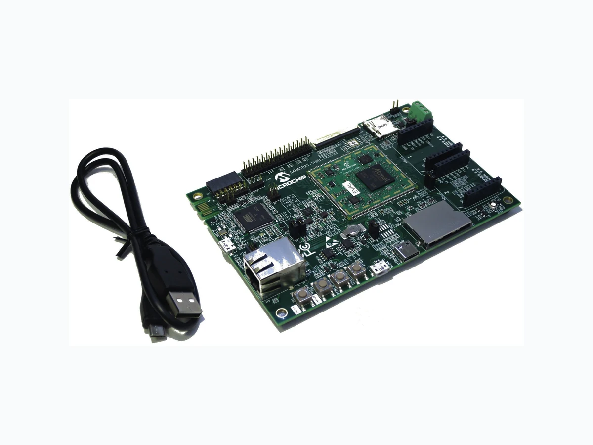
ATSAMA5D27-SOM1 ATMEL
Document overview
- Manufacturer or author: Provided By digicamel.com
- PDF pages: 60
Technical content
describes how to use the kit.
- a baseboard
- a SAMA5D27 SOM soldered on the baseboard
- a SAMA5D27 SIP soldered on the SOM
- a USB cable See the figure below.
Figure 1. SAMA5D27 SOM1 Kit1 Overview
© 2017 Microchip Technology Inc. User Guide DS50002667A-page 2
- Object of Declaration EU Declaration of Conformity for SAMA5D27 SOM1 Kit1 This declaration of conformity is issued by the manufacturer. The development/evaluation tool is designed to be used for research and development in a laboratory environment. This development/evaluation tool is not a Finished Appliance, nor is it intended for incorporation into Finished Appliances that are made commercially available as single functional units to end users under EU EMC Directive 2004/108/EC and as supported by the European Commission's Guide for the EMC Directive 2004/108/EC (8th February 2010). This development/evaluation tool complies with EU RoHS2 Directive 2011/65/EU. This development/evaluation tool, when incorporating wireless and radio-telecom functionality, is in compliance with the essential requirement and other relevant provisions of the R&TTE Directive 1999/5/EC and the FCC rules as stated in the declaration of conformity provided in the module datasheet and the module product page available at www.microchip.com. For information regarding the exclusive, limited warranties applicable to Microchip products, please see Microchip’s standard terms and conditions of sale, which are printed on our sales documentation and available at www.microchip.com. Signed for and on behalf of Microchip Technology Inc. at Chandler, Arizona, USA. SAMA5D27 SOM1 Kit1 © 2017 Microchip Technology Inc. User Guide DS50002667A-page 3
- Introduction
2.1 Document Layout
The document is organized as follows:
- Introduction
- Product Overview – Important information about the kit
- Board Components – Specifications of the kit and high-level description of the major components and interfaces
- Installation and Operation – Instructions on how to get started with the kit
- Errata
- Appendix: Schematics and Layouts – Kit schematics and layout diagrams
2.2 Reference Documents
The following Microchip documents are available and recommended as supplemental reference resources: Type Document Title Available Ref. No./Product Datasheet SAMA5D2 www.microchip.com/SAMA5D2 DS60001476 Datasheet SAMA5D2 System-On-Module (SOM) www.microchip.com/ATSAMA5D27- SOM1 DS60001521 Datasheet SAMA5D2 System-In-Package (SIP) www.microchip.com/SAMA5D2 SIP DS60001484 SAMA5D27 SOM1 Kit1 © 2017 Microchip Technology Inc. User Guide DS50002667A-page 4
- Product Overview
3.1 Kit Contents
The kit includes the following:
- One baseboard with soldered SOM
- One USB cable
3.2 Features
The kit comprises a baseboard with a soldered SAMA5D27 SOM1 module. The module features a SAMA5D27-D1G-CU SIP embedding a 1-Gbit DDR2 SDRAM. The SOM offers a reliable and cost- effective embedded platform for building end products, as well as a small form factor, complemented by many connectivity interfaces. The SOM is a fully-featured industrially-certified single board computer designed for integration into customer applications. The SOM module is a purpose-built small footprint hardware platform equipped with a wide array of high- speed connectivity engineered to support various applications such as IoT endpoints, wearables, appliances or industrial equipment. The SOM integrates a 1-Gbit DDR2 SDRAM, a QSPI memory and a 10/100 Mbps Ethernet controller. 128 GPIO pins are provided by the SOM for general use in the system. All GPIO pins are independent and can be configured as inputs or outputs, with or without pull-up/pull-down resistors. The baseboard features a wide range of peripherals, as well as a user interface and expansion options, including two mikroBUS™ click interface headers to support over 300 MikroElektronika click boards™ and one Pmod™ interface. Table 3-1. Baseboard Features Characteristics Specifications Components Memory One QSPI Flash (unmounted) Tested with Macronix MX25L25673GM2I-08G Crypto One CryptoAuthentication™ device ATECC508 USB Com Port One USB host One USB device One USB HSIC Connector type C Connector type microAB 2-pin header (not populated) Ethernet One Ethernet interface RJ45 connector CAN One CAN interface ATA6561 Video One LCD RGB 24-bit interface One ISC 12-bit interface 50-pin FPC connector 2x15 male connector Storage One standard SD card interface One microSD card interface With 3.3V/1.8V power switch Debug port One J-Link-OB and J-Link-CDC One JTAG interface Microchip SAM3U micro-controller with embedded J-Link firmware SAMA5D27 SOM1 Kit1 © 2017 Microchip Technology Inc. User Guide DS50002667A-page 5
Characteristics Specifications Components Board Monitor One RGB (Red, Green, Blue) LED Four push button switches Power ON, Reset, Wakeup, User Free Expansion One tamper connector One Pmod connector Two mikroBUS interfaces 10-pin male connector 6-pin female connector 2x8-pin female connector Board Supply From USB A and/or USB J-Link-OB 5 VDC Power saving SuperCap – Refer to www.microchip.com for:
- Sample code and technical support
- Linux software and demos
3.3 Specifications
Table 3-2. Kit Specifications Characteristic Specification Board supply voltage USB-powered Temperature Operating: 0°C to +70°C Storage: –40°C to +85°C Relative humidity 0 to 90% (non-condensing) Baseboard dimensions 135 × 90 × 20 mm RoHS status Compliant
3.4 Power Sources
Two options are available to power up the baseboard:
- USB powering through the USB Micro-AB connector (J17 - default configuration)
- Powering through the USB Micro-AB connector on the J-Link-OB Embedded Debugger interface (J10) The two power sources can coexist. A priority mechanism manages the automatic switching between the two. The priority source is J-Link (J10), the secondary source is the USB port (J17). Table 3-3. Electrical Characteristics Electrical Parameter Value Input voltage 5VCC Maximum input voltage 6VCC SAMA5D27 SOM1 Kit1 © 2017 Microchip Technology Inc. User Guide DS50002667A-page 6
Electrical Parameter Value Maximum 3.3VDC current available 1.2A I/O voltage 3.3V only SAMA5D27 SOM1 Kit1 © 2017 Microchip Technology Inc. User Guide DS50002667A-page 7
- Baseboard Components This section covers the specifications of the SAMA5D27 SOM1 Kit1 baseboard and provides a high-level description of the baseboard's major components and interfaces. This document is not intended to provide a detailed documentation about the processor or about any other component used on the baseboard. It is expected that the user will refer to the appropriate documents of these devices to access detailed information.
4.1 Baseboard Overview
The fully-featured SAMA5D27 SOM1 Kit1 baseboard integrates multiple peripherals and interface connectors, as shown in the figure below. Figure 4-1. SAMA5D27 SOM1 Kit1 Baseboard Overview The following picture illustrates the kit block diagram. Figure 4-2. SAMA5D27 SOM1 Kit1 Block Diagram PCB JTAGInterface SPI FlashSystem Supplies POWER REGULATOR GPIO, SHDN UART MPU JTAG Interface JTAG LCD ISC TWI FLEXCOM RJ45 ETH CAN CAN mikroBUS Interface mikroBUS Interface GPIO USB A&B SDHC0 SDHC1 RGB Leds USB Detection DEBUG Interface Push Button Reset, Wkup DisBoot, User Pmod Interface PIOBU Connector ISC Connector 3v3, 1v8 Power Cap VDDBU JTAG SWITCH USB-A Connector USB-B Connector uSD Connector SD Card Connector GPIO USB Power Switch 3.3V, 1.8V FPC Connector POWER MONITOR SAMA5D27-SOM1 DDR2, QSPI, EEPROM, ETHERNET PHY, GPIOsJLINK-OB JLINK-CDC Dual LED Function Select QSPI GPIO Function Select Power Switch CRYPTO ECC508 Tri State JLINK Power 5V/3.3V USB Connector SAMA5D27 SOM1 Kit1 © 2017 Microchip Technology Inc. User Guide DS50002667A-page 8
4.1.1 Default Jumper Settings
The figure below shows the default jumper settings. Jumpers in red are configuration items and current measurement points. The following table describes the functionality of the jumpers. Figure 4-3. Default Jumper Settings Table 4-1. Jumper Settings Jumper Default Function J1 Closed VDD_MAIN_5V current measurement J2 Closed VDD_3V3 SOM current measurement J4 Closed VDDBU current measurement J7 Open Enables J-Link-OB (closed=disable) J8 Open Erases SAM3U firmware code (closed=erase at power-up) Warning: Must remain open. If closed, the SAM3U contents are erased and J-Link functionality is discarded. J9 Open Enables JTAG-CDC (closed=disable) J13 Open Disables SOM boot memories (closed=disable) SAMA5D27 SOM1 Kit1 © 2017 Microchip Technology Inc. User Guide DS50002667A-page 9
J22 Closed Enables 3.3V power mikroBUS1 (closed=enable) J28 Closed Enables 3.3V power mikroBUS2 (closed=enable)
4.1.2 Baseboard Connectors
The following table describes the interface connectors on the SAMA5D27 SOM1 Kit1 baseboard. Table 4-2. Baseboard Interface Connectors Connector Interfaces to J5 CLK_AUDIO test point (not populated) J6 PCB-edge JTAG connector for factory-programming the J-Link-OB J10 USB-A MicroAB, J-Link-OB port J11 MPU SAMA5D27 JTAG 10-pin IDC connector J12 Standard SDMMC0 connector J14 microSD connector J15 Ethernet RJ45 connector J16 CAN 3-pin screw connector J17 USB-A MicroAB connector J18 HSIC 2-point header J19 USB-B type C connector J20-J23 Jumper to select Pmod functions J21 Pmod connector J24-25 mikroBUS1 connectors J26 Expansion TFT LCD connector for display module J27 ISC connector J29-J30 mikroBUS2 connectors J31 Tamper and analog comparator connector J32 SHDN test point (not populated)
4.2 Function Blocks
4.2.1 SAMA5D27 SOM1
The SAMA5D27 SOM1 main features are as follows:
- Ultra-small SIP (SAMA5D27-D1G-CU) embedding an ultra-low-power SAMA5D27 Arm ® Cortex®- A5 processor and a 1 Gbit DDR2 SDRAM memory
- SST26VF064 64 Mb QSPI Flash
- 24AA02E48 2 Kb serial E 2PROM with preprogrammed EUI node identity SAMA5D27 SOM1 Kit1 © 2017 Microchip Technology Inc. User Guide DS50002667A-page 10
- MIC2800 power management device
- KSZ8081RNA Ethernet Phy 10/100 MHz RMII Refer to the SAMA5D27 SOM1 datasheet for more information. Figure 4-4. SAMA5D27 SOM1 Block Diagram MPU + DDR 2 1Gb SAMA5D27-SiP L FB GA289 14 x 14 mm Pitch 0.8 mm 64Mbit Serial QUAD I/O Flash Memory SST26V F064B -104I/MF 2K Serial E E PR OM with E UI-48Node Identity 24AA02E 48T -I/OT ΤΜ 10B ASE -T / 100B ASE -TX PHY With R MII Support K SZ8081R NAIA Power Management Unit MIC2800-G4JY ML V DDSDHC V DDISC V DDB U MAIN 3.3V TWI Interface
103 Mixable I/O
Up to 6 * PT C B uttons Up to 4 * ADC Inputs TWI Interface Up to 4 * UAR T 2 * SPI Interfaces Up to 4 * FL E X COM L CD Interface up to 24-bit SSC Interface Mono PDMIC Interface Up to 2 * CAN I²S Interface SDIO Interface SD-CAR D Interface E xternal QSPI Connection JT A G & DB GU Interfaces DE B UG SY STE M MISC USB Dev. USB Host HSIC B A CK UP7 * PIOB U R X D W AK E UP R E SET SHUTDOWN CL K _A UDIO COMPP / COMPN Disable B oot
4.2.2 Power Supply Topology and Power Distribution
4.2.2.1 Input Power Options
As described previously, the board power source can come through either a USB connector (J10 or J17) connected to a PC or a 5VDC-USB power supply unit. Such USB power source is sufficient to supply the board in most applications. It is important to note that when the USB-powered operation is used, the USB-B Host port has a limited powering capability for the device connected to it down the way. If the USB-B Host port is required to provide full powering capabilities to a target device, then it is recommended to use an external DC-USB power supply unit as main power source for the whole system rather than a PC or a USB hub. The baseboard embeds a local power management stage comprising two sets of load switches, respectively implemented by MOSFET DMP2160 and DC/DC converter MIC23451. The following figure is a schematic of the power options. SAMA5D27 SOM1 Kit1 © 2017 Microchip Technology Inc. User Guide DS50002667A-page 11
Figure 4-5. Input Powering VBUS_JLINK VDD_MAIN_5V VBUS_USBA 100K Q1-2 DMP2160 8 4 TSW-102-07-G-S Q2-2 DMP2160 8 4 100nF 10K 100nF Q1-1 DMP2160 Q2-1 DMP2160 R12 100K DNP 100K 100nF Note: PC/USB-powered operation eliminates additional wires and batteries. It is the preferred mode of operation for any project that requires only a 5V source at up to 500 mA. Jumper J1 is used to perform MAIN_5V current measurements on the baseboard.
4.2.2.2 Power Supply Requirements and Restrictions
Detailed information on the device power supplies is provided in tables “SAMA5D2 Power Supplies” and “Power Supply Connections” in the SAMA5D2 Series datasheet.
4.2.2.3 Power-up and Power-down Considerations
Power-up and power-down considerations are described in section “Power Considerations” of the SAMA5D2 Series datasheet. Caution: The power-up and power-down sequences provided in the SAMA5D2 Series datasheet must be respected for reliable operation of the device. These are respected by the on-board MIC23451.
4.2.2.4 Power Management
The baseboard power management uses a MIC23451 PMIC, which is a triple synchronous buck regulator with HyperLight Load® mode featuring a power good indicator. The triple DC-DC step down power regulator delivers two outputs: 3.3V/2A and 1.8V/2A. While the external power is being applied, the baseboard can be shut down by software and then woken up by action on the PB2 push button, which activates the WKUP signal. The figure below shows the power management scheme. SAMA5D27 SOM1 Kit1 © 2017 Microchip Technology Inc. User Guide DS50002667A-page 12
Figure 4-6. Baseboard Power Management BB_PWR_GOOD VOUT1 VOUT2 VDD_SDHC_1V8 VDDIN_3V3 VOUT3 VDD_3V3 VDD_MAIN_5V VOUT2 VOUT1 VOUT3 VDD_SDHC_3V3 PD8 R130 10uF 158K R16 10K R11 309K 180ohm at 100MHz 1 2 4.7uF 180ohm at 100MHz 1 2 TSW-102-07-G-S R10 10K 1uH R17 0R DNP 301K 71K5 4.7uF R19 0R DNP R4 100R MIC23451 PVIN1 PVIN2 PVIN3 AVIN1 AVIN2 AVIN3 PG1 PG2 PG3 EN1 EN2 EN3 SW1 SW2 SW3 SNS1 SNS2 SNS3 FB1 FB2 FB3 PGND1 PGND2 PGND3 AGND1 AGND2 EP1 EP2 10uF R13 10K 309K 4.7uF 1uH TSW-102-07-G-S R7 10K DNP R14 71K5 C10 4.7uF 10uF R15 10K DNP R18 10K 180ohm at 100MHz 1 2 1uH 180ohm at 100MHz 1 2 One PIO (PD8) is used to check the status of the main regulator. Table 4-3. Power Good Signal PIO Mnemonic Signal Description PD8 BB_PWR_GOOD High level = power is established and at correct level
4.2.2.5 Supply Group Configuration
The main regulator provides the 3.3V for the SOM and all power supplies required by the baseboard:
- 3.3V SOM (VDDIN_3V3)
- 3.3V VDDSDHC (3.3V or 1.8V)
- 3.3V baseboard (VDD_3V3)
- 3.3V VDDBU Figure 4-7. SOM Power Lines VDDIN_3V3 VDDBU VDDSDHC V DDIN_3V3 C21 2.2uF DNP C17 100nF C16 2.2uF DNP ATSAMA5D27-SOM1 U3F VDDBU VDDIN_3V3_1 VDDIN_3V3_2 VDDISC VDDSDHC GND_1 GND_2 GND_3 GND_4 GND_5 GND_6 GND_7 GND_8 GND_9 GND_10 GND_11 GND_12 GND_13 GND_14 GND_15 GND_16 GND_17 GND_18 107 GND_19 130 GND_20 131 GND_21 149 GND_22 166 GND_23 171 GND_24 176 GND_0 C18 100nF C24 100nF C19 2.2uF DNP C22 100nF C23 2.2uF DNP C20 100nF
4.2.2.6 Backup Power Supply
The baseboard features a power source in order to permanently power the backup area of the SAMA5D2 device (refer to the SAMA5D2 Series datasheet). A super capacitor (C14) sustains such permanent power to VDDBU when all system power sources are off. SAMA5D27 SOM1 Kit1 © 2017 Microchip Technology Inc. User Guide DS50002667A-page 13
Figure 4-8. VDDBU Powering Options (Super)-Capacitor energy storage VDDBU VDD_3V3 BAT54C TSW-102-07-G-S + C14 0.2F/3.3V C13 100nF RB160M-60TR R20 100R
4.2.3 Shutdown Circuitry
On the baseboard, this circuitry is implemented but inhibited by default (R131 is not populated). The SHDN signal, output of the shutdown controller, signals the shutdown request to the power supply. This output signal is supplied by VDDBU that is present in Backup mode The shutdown controller manages the main power supply and is connected to the ENABLE input pin of the DC/DC converter providing the main power supplies of the system. Figure 4-9. Shutdown Controller PO W ER O N VDDBU VDD_MAIN_5V SHDN R132 100K R131 0R DNP R128 10K BSS1381 BSS1381 R129 100K R127 10K PB3
4.2.4 Push Button Switches
The baseboard features four push buttons:
- One reset push button (PB1). When pressed and released, the baseboard is reset.
- One wakeup push button (PB2) connected to the SAMA5D27 WKUP pin, used to exit the processor from Backup mode.
- One power-on button (PB3). Figure 4-10. System Push Buttons NRST WAKE UP VDDBU VDDBU NRST W KUP R126 100K DNP R23 100R R24 100R R121 10K PB2 PB1
- One user momentary push button (PB4) connected to PIO PA29, and optionally to PIOBU1. The wakeup is available only if the shutdown controller is used (see figure Shutdown Controller). SAMA5D27 SOM1 Kit1 © 2017 Microchip Technology Inc. User Guide DS50002667A-page 14
Figure 4-11. User Push Button PIOBU1 PA29 PB4 R72 100R DNP R73 100R
4.2.5 Additional Memories
One additional memory, QSPI device U9, can be soldered on the baseboard. This QSPI Flash memory uses the same PIOs as the SOM QSPI. Such configuration makes it possible to choose between two bootable memories. The figure below illustrates the QSPI memory implementation. Figure 4-12. Optional QSPI Serial Data Flash on Baseboard Q SPI1_SCK Q SPI1_IO 0 Q SPI1_IO 1 Q SPI1_IO 2 Q SPI1_IO 3 CS_QSPI1 VDD_3V3 VDD_3V3 PB5 PB7 PB8 PB9 PB10 MX25L25673GM2I-08G DNP SI/SIO0 SO/SIO1 SIO2 SIO3 VCC CS# SCLK GND R53 10K C52 100nF R54 10K Table 4-4. QSPI Signal Descriptions PIO Mnemonic Shared PIO Signal Description PB5 QSPI1_SCK QSPI on SOM Clock PB6 QSPI1_CS QSPI on SOM Chip select PB7 QSPI0_IO0 QSPI on SOM Data0 PB8 QSPI0_IO1 QSPI on SOM Data1 PB9 QSPI0_IO2 QSPI on SOM Data2 PB10 QSPI0_IO3 QSPI on SOM Data3
4.2.5.1 CS Disable Boot
One jumper (J13) controls the selection (CS#) of the bootable memory components (QSPI) using a non- inverting 3-state buffer. Figure 4-13. CS Disable Boot Q SPI1_CS (SOM ) PB6 CS_QSPI1 VDD_3V3 VDD_3V3 DISABLE_BOOT PB6 J13 TSW-102-07-G-S C55 100nF R60 10K R59 10K U10 NL17SZ125 DNP 1 OE 2 IN
3 GND
The rule of operation is:
- PB1 (RESET) pressed and J13 open = booting from QSPI on SOM
- PB1 (RESET) pressed and J13 closed = booting from QSPI on baseboard if fitted. The QSPI on SOM is disabled. Refer to the SAMA5D2 Series datasheet for more information on standard boot strategies and sequencing. SAMA5D27 SOM1 Kit1 © 2017 Microchip Technology Inc. User Guide DS50002667A-page 15
4.2.6 Secure Digital Multimedia Card (SDMMC) Interface
The SD (Secure Digital) Card is a non-volatile memory card format used as a mass storage memory in mobile devices.
4.2.6.1 Secure Digital Multimedia Card (SDMMC) Controller
The baseboard features two Secure Digital Multimedia Card (SDMMC) interfaces that support the MultiMedia Card (e.MMC) Specification V4.41, the SD Memory Card Specification V3.0, and the SDIO V3.0 specification. It is compliant with the SD Host Controller Standard V3.0 Specification.
- The SDMMC0 interface is connected to a standard SD card interface.
- The SDMMC1 interface is connected to a microSD card interface.
4.2.6.2 SDMMC0 Card Connector (J12)
A standard MMC/SD card connector, connected to SDMMC0, is mounted on the top side of the baseboard. The SDMMC0 communication is based on a 12-pin interface (clock, command, write protect, power switch and data (8)). A card detection switch is included. The figure below illustrates the SDMMC0 interface implementation. Figure 4-14. SDMMC0 SDMMC0_CD SDMMC0_DA1 SDMMC0_DA0 SDMMC0_CK SDMMC0_CDA SDMMC0_DA3 SDMMC0_DA2 SDMMC0_DA4 SDMMC0_DA5 SDMMC0_DA6 SDMMC0_DA7 SDMMC0_WP VDDSDHC VDD_3V3 PA0 PA1 PA2 PA3 PA4 PA5 PA6 PA7 PA8 PA9 PA12 PA13 R52 J12 SD/MMCPlus CARD R56 10K C53 10uFR58 10K RR2 68K RR1 68K C54 100nFR57 10K SAMA5D27 SOM1 Kit1 © 2017 Microchip Technology Inc. User Guide DS50002667A-page 16
Figure 4-15. Standard SD Socket J12 Location The table below describes the pin assignment of SDMMC connector J12. Table 4-5. Standard SD Socket J12 Pin Assignment Pin No Mnemonic PIO Signal Description
1 SDMMC0_DAT3_PA5 PA5 Data line
2 SDMMC0_CMD_PA1 PA1 Command/response line
3 GND – GND
4 VDDSDHC (3.3V or 1.8V) – Power line
5 SDMMC0_CK_PA0 PA0 Clock line
6 SDMMC0_CD_PA13 PA13 Card detect
7 SDMMC0_DAT0_PA2 PA2 Data line
8 SDMMC0_DAT1_PA3 PA3 Data line
9 SDMMC0_DAT2_PA4 PA4 Data line
10 SDMMC0_DAT4_PA6 PA6 Data line
11 SDMMC0_DAT5_PA7 PA7 Data line
© 2017 Microchip Technology Inc. User Guide DS50002667A-page 17
Pin No Mnemonic PIO Signal Description
12 SDMMC0_DAT6_PA8 PA8 Data line
13 SDMMC0_DAT7_PA9 PA9 Data line
14 SDMMC0_WP_PA12 PA12 Write protect signal
15 GND – GND
16 GND – GND
Table 4-6. SDMMC1 Power Command PIO Mnemonic Signal Description PA11 SDMMC0_VDDSEL Select 3.3V or 1.8V
4.2.6.3 SDMMC1 Card Connector (J14)
A microSD card connector, connected to SDMMC1, is mounted on the top side of the baseboard. The SDMMC1 communication is based on a 6-pin interface (clock, command and four data). A card detection switch is included. The microSD connector can be used to connect any microSD card for mass storage. Figure 4-16. SDMMC1 microSD SDMMC1_CD SDMMC1_DAT0 SDMMC1_DAT1 SDMMC1_CK SDMMC1_CDA SDMMC1_DAT3 SDMMC1_DAT2 VDD_3V3 PA18 PA19 PA20 PA21 PA22 PA28 PA30 R62 10K C57 100nF SW1 SW2 J14 DM3AT-SF-PEJM5 R61 0R R63 10K C56 10uFRR3 68K SAMA5D27 SOM1 Kit1 © 2017 Microchip Technology Inc. User Guide DS50002667A-page 18
Figure 4-17. microSD Socket J14 Location The table below describes the pin assignment of microSD connector J14. Table 4-7. microSD Socket J14 Pin Assignment Pin No Mnemonic PIO Signal Description
1 SDMMC1_DAT2 PA20 Data bit 2
2 SDMMC1_DAT3 PA21 Data bit 3
3 SDMMC1_CDA PA28 Command
4 VCC – 3.3V supply voltage
5 SDMMC1_CK PA22 Clock
6 GND – Common ground
7 SDMMC1_DAT0 PA18 Data bit 0
8 SDMMC1_DAT1 PA19 Data bit 1
9 SW1 GND Ground
10 SDMMC1_CD PA30 Card detection switch
11 GND – Common ground
12 GND – Common ground
© 2017 Microchip Technology Inc. User Guide DS50002667A-page 19
Pin No Mnemonic PIO Signal Description
13 GND – Common ground
14 GND – Common ground
4.2.6.4 CryptoAuthentication™
ATECC508A is a member of the CryptoAuthentication family of crypto engine authentication devices with highly secure hardware-based key storage. The ATECC508A features a flexible command set enabling use in many applications, including network/IoT node protection, anti-counterfeiting, firmware or media protection, secure data storage and user password checking. The device (U11) is mounted in an 8-lead UDFN package. For more information, refer to the ATECC508A datasheet on www.microchip.com. Figure 4-18. CryptoAuthentication ATECC508 TWD0 TWCK0 VDD_3V3 PD21 PD22 U11 ATECC508A NC1 NC2
2 NC3
Table 4-8. ATECC508 PIO Signal Descriptions PIO Mnemonic Shared Signal Description PD21 TWD0 SOM E2PROM 24AA02E48 TWI data PD22 TWCK0 SOM E2PROM 24AA02E48 TWI clock
4.2.7 Communication Interfaces
This section describes the signals and connectors related to the ETH, USB and CAN communication interfaces.
4.2.7.1 Ethernet 10/100 (GMAC) Port
The on-board SOM integrates a 10/100 Mbps Ethernet controller (KSZ8081RNA) allowing direct connection to any 10/100 Mbps Ethernet-based Local Area Network, for full interaction with local servers and wide area networks such as the Internet. ETH signals from the SOM are connected to a RJ45 MagJack. Additionally, for monitoring and control purposes, a LED functionality is carried on the RJ45 connector to indicate link status. SAMA5D27 SOM1 Kit1 © 2017 Microchip Technology Inc. User Guide DS50002667A-page 20
Figure 4-19. Ethernet PHY LINK ETH_LED0 TX+ RX- RX+ TX- EARTH_ETH EARTH_ETH GND_ETH V DD_3V3 ETH_LED0 TX+ TX- RX+ RX- C64 100nF C63 100nF R69 470R 75 75 1nF TD+ TD- CT NC RD- CT TX+ TX- RX+ RX- RD+ Left Green LED Right yellow LED J15 Figure 4-20. Ethernet RJ45 Connector J15 Location The table below describes the pin assignment of Ethernet connector J15. Table 4-9. Ethernet RJ45 Connector J15 Pin Assignment Pin No Mnemonic Signal Description
1 TX+ Transmit positive differential pair
2 TX- Transmit negative differential pair
3 RX+ Receive positive differential pair
4 Decoupling capacitor –
© 2017 Microchip Technology Inc. User Guide DS50002667A-page 21
Pin No Mnemonic Signal Description
5 Decoupling capacitor –
6 RX- Receive negative differential pair
7 NC –
8 EARTH / GND Common ground
9 ACT LED (A) LED activity (not used)
10 ACT LED (K) LED activity (not used)
11 LINK LED (K) LED link connection
12 LINK LED (A) LED link connection
13 EARTH / GND Common ground
14 EARTH / GND Common ground
15 NC –
16 NC –
4.2.7.2 USB Interfaces
The USB (Universal Serial Bus) is a hot-pluggable general-purpose high-speed I/O standard for computer peripherals. The standard defines connector types, cabling, and communication protocols for interconnecting a wide variety of electronic devices. The USB 2.0 Specification defines data transfer rates as high as 480 Mbps (also known as High Speed USB). A USB host bus connector uses 4 pins: a power supply pin (5V), a differential pair (D+ and D- pins) and a ground pin. The baseboard features three USB communication ports named USB-A to USB-C:
- USB-A device interface – One USB device standard micro-AB connector. – This port offers a VBUS detection function through the R81-R83 resistor ladder. – The USB-A port is used as a secondary power source and as a communication link for the baseboard, and derives power from the PC over the USB cable. In most cases, this port is limited to 500 mA.
- USB-B (host port B high- and full-speed interface) – One USB host type C connector. – The USB-B host port is equipped with a 500 mA high-side power switch.
- USB-C (High-Speed Inter-Chip/HSIC port) – One USB high-speed host port with an HSIC interface. – The port is connected to a single 2-pin header (not populated).
4.2.7.3 USB-A Interface
The figure below shows the USB implementation on the USB-A port terminated on a micro USB type microAB connector. The USB-A port (J17) features a VBUS insert detection function through ladder-type resistors R70 and R71. SAMA5D27 SOM1 Kit1 © 2017 Microchip Technology Inc. User Guide DS50002667A-page 22
Table 4-11. USB-A Connector J17 Pin Assignment Pin No Mnemonic Signal Description
1 VBUS 5V power
2 DM Data minus
3 DP Data plus
4 ID On-the-go identification
5 GND Common ground
4.2.7.4 USB-B Interface
The figure below shows the USB implementation on the USB-B port terminated on USB Type C connector J19. Figure 4-23. USB-B Type C Connector Top/Bot Top/Bot USBB_VBUS_5V EARTH_USB_B EARTH_USB_B VDD_3V3 USBB_DP USBB_DM R79 36K C69 330pF J19 USB C VBUS1 GND8 GND5 GND3 B12 GND2 A12 GND1 VBUS4 VBUS2 VBUS3 GND4 TX1+ TX1- RX1+ B11 RX1- B10 D1+ D1- D2+ D2- CC1 TX2+ TX2- RX2+ A11 RX2- A10 SBU1 SBU2 CC2 GND7 GND6 R78 36K C70 330pF SAMA5D27 SOM1 Kit1 © 2017 Microchip Technology Inc. User Guide DS50002667A-page 24
Figure 4-24. USB-B Type C Connector J19 Location The table below describes the pin assignment of USB-B connector J19. Table 4-12. USB-B Connector J19 Pin Assignment Pin No Mnemonic Signal Description A1 GND Ground return A2 SSTXp1 SuperSpeed differential pair #1, TX, positive (NOT USED) A3 SSTXn1 SuperSpeed differential pair #1, TX, negative (NOT USED) A4 VBUS Bus power A5 CC1 Configuration channel A6 DP1 USB 2.0 differential pair, position 1, positive A7 DN1 USB 2.0 differential pair, position 1, negative A8 SBU1 Sideband use (SBU) A9 VBUS Bus power A10 SSRXn2 SuperSpeed differential pair #2, RX, negative (NOT USED) A11 SSRXp2 SuperSpeed differential pair #2, RX, positive (NOT USED) A12 GND Ground return SAMA5D27 SOM1 Kit1 © 2017 Microchip Technology Inc. User Guide DS50002667A-page 25
Pin No Mnemonic Signal Description B12 GND Ground return B11 SSRXp1 SuperSpeed differential pair #1, RX, positive (NOT USED) B10 SSRXn1 SuperSpeed differential pair #1, RX, negative (NOT USED) B9 VBUS Bus power B8 SBU2 Sideband use (SBU) B7 DN2 USB 2.0 differential pair, position 2, negative B6 DP2 USB 2.0 differential pair, position 2, positive B5 CC2 Configuration Channel B4 VBUS Bus power B3 SSTXn2 SuperSpeed differential pair #2, TX, negative (NOT USED) B2 SSTXp2 SuperSpeed differential pair #2, TX, positive (NOT USED) B1 GND Ground return USB-B Power Switch The USB-B Host port is equipped with a 500 mA high-side power switch for self-powered and bus- powered applications. If the client device is bus-powered, the carrier can supply a 5V, 500mA power to the client device. The USBB_EN_5V_PA27 signal controls the power switch and current limiter, the Microchip MIC2025, which in turn supplies power to a bus-powered client device. Per the USB specification, bus-powered USB 2.0 devices are limited to a maximum of 500 mA. The MIC2025 limits the current and indicates an overcurrent with the USBB_OVCUR_PD19 signal. Figure 4-25. USB-B Power Switch EN: Active High USBB_POWR_EN USBB_OVCUR USBB_VBUS_5V VDD_MAIN_5V VDD_3V3 PD19 PA27 R138 10K U13 MIC2025 EN FLG NC1 OUT_2 OUT_1 GND IN NC2 C67 10uF L12 180ohm at 100MHz 1 2 C68 100nF C66 100nF R77 10K Table 4-13. Power Switch PIO Signal Descriptions PIO Mnemonic Shared Signal Description PA27 USBB_POWR_EN USBB_EN_5V – Power switch enable (active high) PD19 USBB_OVCUR – Indicates overcurrent (open drain)
4.2.7.5 HSIC Interface
High-Speed Inter-Chip (HSIC) is a standard for USB chip-to-chip interconnect with a 2-signal (strobe, data) source synchronous serial interface using 240 MHz DDR signaling to provide only high-speed 480 Mbps data rate. The interface operates at high speed, 480 Mbps, and is fully compatible with existing USB software stacks. It meets all data transfer needs through a single unified USB software stack. SAMA5D27 SOM1 Kit1 © 2017 Microchip Technology Inc. User Guide DS50002667A-page 26
The HSIC interface is connected to two-point header J18. This connector is not mounted. Figure 4-26. HSIC Interface J18 Top/Bot Top/Bot HSIC_DAT A HSIC_STRB J18 TSW-102-07-G-S DNP
4.2.7.6 CAN Interface
This section lists the signals related to the Controller Area Network (CAN) interface. The CAN interface transmits and receives signals from the SOM. CAN PIOs PC26 and PC27 are connected to the CAN transceiver (ATA6561) and the output signals from the transceiver are connected to the screw connector (J16) physically located on top of the baseboard. Figure 4-27. CAN Interface CANTX1 CANRX1 VDD_3V3 VDD_MAIN_5V PC26 PC27 U12 ATA6561-GBQW TXD GND VCC RXD VIO CANL 6CANH STBY PAD R66 62R C59 100nF R68 C61 100nF J16 Screw 3x1 R67 62R C60 4.7uF R65 C62 15pF Figure 4-28. CAN Connector J16 Location SAMA5D27 SOM1 Kit1 © 2017 Microchip Technology Inc. User Guide DS50002667A-page 27
Table 4-14. CAN Connector J16 Pin Assignment Pin Mnemonic Signal Description
1 CANH Differential positive
2 CANL Differential negative
3 GND Ground
4.3 External Interfaces
4.3.1 LCD TFT Interface
The baseboard provides a FPC connector with 24 bits of data and control signals to the LCD interface. Other signals are used to control the LCD and are available on connector J26: TWI, SPI, two GPIOs for interrupt, 1-wire and power supply lines. This connector is used to connect LCD display type TM43xx series or TM7000 series from PDA Inc (www.pdaatl.com). A 50-pin FPC (J26) header is provided on the baseboard to interface the LCD module with 24-bit parallel RGB. The connector provides two PIOs as interrupts, one SPI and a TWI port to interface the MaXTouch touch controller or QTouch button controller embedded on the LCD module. In order to operate correctly out of the processor with various LCD modules, two voltage lines are available: 3.3V and 5VCC (default). Both are selected by 0R resistors R81 and R83. Figure 4-29. LCD Expansion Header Interface SPI0_ SPCK SPI0_ MOSI SPI0_ MISO SPI0_NPCS0 LCDDAT0 LCDDAT6 LCDDAT5 LCDDAT4 LCDDAT3 LCDDAT2 LCDDAT1 LCDDAT11 LCDDAT10 LCDDAT9 LCDDAT8 LCDDAT7 LCDDAT16 LCDDAT15 LCDDAT14 LCDDAT13 LCDDAT12 LCDDAT22 LCDDAT21 LCDDAT20 LCDDAT19 LCDDAT18 LCDDAT17 LCDDEN LCDHSYNC LCDVSYNC LCDPCK LCDDAT23 IRQ1 IRQ2 LCDPWM LCDDISP TWD_LCD TWCK_LCD VDD_3V3VDD_MAIN_5V PB12 PB13 PB14 PB15 PB16 PB17 PB18 PB19 PB20 PB21 PB22 PB23 PB24 PB25 PB26 PB27 PB28 PB29 PB30 PB31 PC0 PC1 PC2 PC5 PC6 PC7 PC8 PA14 PC4 PA15 PA16 PA17 PD1 PC25 LCD_PWM_PC3 NRST PB11 PA17 J26 R81 0R DNP R119 100R R85 0R R83 0R SAMA5D27 SOM1 Kit1 © 2017 Microchip Technology Inc. User Guide DS50002667A-page 28
Figure 4-30. LCD Connector J26 Location The table below describes the pin assignment of LCD connector J26. Table 4-15. LCD Connector J26 Pin Assignment Pin No Signal PIO Signal RGB Interface Function
1 ID PA17 ID Shared with SPI_NPCS0 pin 40
2 GND GND GND GND
3 LCDDAT0 PB11 D0 Data line (BLUE0)
4 LCDDAT1 PB12 D1 Data line (BLUE1)
5 LCDDAT2 PB13 D2 Data line (BLUE2)
6 LCDDAT3 PB14 D3 Data line (BLUE3)
7 – – GND GND
8 LCDDAT4 PB15 D4 Data line (BLUE4)
9 LCDDAT5 PB16 D5 Data line (BLUE5)
10 LCDDAT6 PB17 D6 Data line (BLUE6)
11 LCDDAT7 PB18 D7 Data line (BLUE7)
12 – GND GND GND SAMA5D27 SOM1 Kit1 © 2017 Microchip Technology Inc. User Guide DS50002667A-page 29
Pin No Signal PIO Signal RGB Interface Function
13 LCDDAT8 PB19 D8 Data line (GREEN0)
14 LCDDAT9 PB20 D9 Data line (GREEN1)
15 LCDDAT10 PB21 D10 Data line (GREEN2)
16 LCDDAT11 PB22 D11 Data line (GREEN3)
17 – – GND GND
18 LCDDAT12 PB23 D12 Data line (GREEN4)
19 LCDDAT13 PB24 D13 Data line (GREEN5)
20 LCDDAT14 PB25 D14 Data line (GREEN6)
21 LCDDAT15 PB26 D15 Data line (GREEN7)
22 – GND GND GND
23 LCDDAT16 PB27 D16 Data line (RED0)
24 LCDDAT17 PB28 D17 Data line (RED1)
25 LCDDAT18 PB29 D18 Data line (RED2)
26 LCDDAT19 PB30 D19 Data line (RED3)
27 – – GND GND
28 LCDDAT20 PB31 D20 Data line (RED4)
29 LCDDAT21 PC0 D21 Data line (RED5)
30 LCDDAT22 PC1 D22 Data line (RED6)
31 LCDDAT23 PC2 D23 Data line (RED7)
32 – GND GND GND
33 LCDPCK PC7 PCLK Pixel clock
34 LCDVSYNC PC5 VSYNC/CS Vertical sync
35 LCDHSYNC PC6 HSYNC/WE Horizontal sync
36 LCDDEN PC8 DATA_ENABLE Data enable
37 SPI_SPCK PA14 SPI_SCK SPI clock
38 SPI_MOSI PA15 SPI_MOSI SPI Master OUT Slave IN
39 SPI_MISO PA16 SPI_MISO SPI Master IN Slave OUT
40 SPI_NPCS0 PA17 SPI_CS SPI chip select
41 LCDDISP PC4 ENABLE Display enable signal
42 TWD PD4 TWI_SDA I2C data line (maXTouch)
43 TWCK PD5 TWI_SCL I2C clock line (maXTouch)
44 GPIO PD1 IRQ1 maXTouch interrupt line
© 2017 Microchip Technology Inc. User Guide DS50002667A-page 30
Pin No Signal PIO Signal RGB Interface Function
45 GPIO PC25 IRQ2 Interrupt line for other I2C devices
46 LCDPWM PC3 PWM Backlight control
47 RESET nRST RESET Reset for both display and maXTouch
48 Main_5V/3V3 VCC VCC 3.3V or 5V supply (R81/R83 selected) 49 Main_5V/3V3 VCC VCC 3.3V or 5V supply (R81/R83 selected)
50 GND GND GND GND
4.3.2 Image Sensor (ISC) Interface
This section describes the signals and connectors related to the ISC interface. The Image Sensor Controller (ISC) system manages incoming data from a parallel or serial CSI-2 based CMOS/CCD sensor. The system supports a single active interface, as well as the ITU-R BT 656/1120 422 protocol with an 8-bit or 10-bit data width and raw Bayer format. The internal image processor includes adjustable white balance, color filter array interpolation, color correction, gamma correction, 12-bit to 10- bit compression, programmable color space conversion, as well as horizontal and vertical chrominance subsampling module. Figure 4-31. ISC Interface ISC_D10 ISC_D8 ISC_D6 ISC_D4 ISC_D2 ISC_D0 ISC_PCK ISC_HSYNC ISC_VSYNC ISC_MCK ISC_PWD ISC_D11 ISC_D9 ISC_D7 ISC_D5 ISC_D3 ISC_RST ISC_D1 TWD_ISC PC22 PC21 PC19 TWCK_ISC PC18 PC20 VDD_3V3 PC9 PC10 PC11 PC12 PC13 PC14 PC15 PC16 PC17 PC23 PC24 PD6 PD7 J27 TSW-115-07-G-D 1 2 3 4 5 6 7 8 9 10 11 12 21 22 23 24 25 26 27 28 29 30 SAMA5D27 SOM1 Kit1 © 2017 Microchip Technology Inc. User Guide DS50002667A-page 31
Figure 4-32. ISC Connector J27 Location The table below describes the pin assignment of ISC connector J27. Table 4-16. ISC Connector J27 Pin Assignment SAMA5D27 Signal Pin No Signal SAMA5D27 Function PIO PIO Function 3.3V power – VDD_3V3 1 2 GND – Ground 3.3V power – VDD_3V3 3 4 GND – Ground Reset PD6 ISC_RST 5 6 ISC_PWD PD7 Power down TWI clock PD5 TWCK_ISC 7 8 TWD_ISC PD4 TWI data Ground – GND 9 10 ISC_MCK PC24 Master clock Ground – GND 11 12 ISC_VSYN C PC22 Vertical sync Ground – GND 13 14 ISC_HSYN C PC23 Horizontal sync Ground – GND 15 16 ISC_PCK PC21 Clock SAMA5D27 SOM1 Kit1 © 2017 Microchip Technology Inc. User Guide DS50002667A-page 32
SAMA5D27 Signal Pin No Signal SAMA5D27 Function PIO PIO Function Ground – GND 17 18 ISC_D0 PC9 Data0 Data1 PC10 ISC_D1 19 20 ISC_D2 PC11 Data2 Data3 PC12 ISC_D3 21 22 ISC_D4 PC13 Data4 Data5 PC14 ISC_D5 23 24 ISC_D6 PC15 Data6 Data7 PC16 ISC_D7 25 26 ISC_D8 PC17 Data8 Data9 PC18 ISC_D9 27 28 ISC_D10 PC19 Data10 Data11 PC20 ISC_D11 29 30 GND – Ground Note: ISC and LCD share the same TWI interface.
4.3.3 RGB LED
The baseboard features one RGB LED which can be controlled by the user. The three LED cathodes are controlled via GPIO PWM or timer/counter pins. Figure 4-33. RGB LED Indicators LED_Red LED_Green LED_blue VDD_3V3 PB1 PA31 PA10 R74 2K2 R137 10K BSS138 R136 100R RGB Red Green Blue Anode Q10 BSS138 BSS138 R135 100R R76 1K R133 10K R134 100R R75 2K2 Table 4-17. RGB LED PIOs Signal Shared PIO Function LED_RED – PA10 TIOA1 LED_GREEN PWM MBUS1 PB1 PWML1 LED_BLUE PWM MBUS2 PA31 PWML0
4.4 Debugging Capabilities
The baseboard includes two main debugging interfaces to provide debug-level access to the SAMA5D2:
- One UART through USB J-Link-CDC
- Two JTAG interfaces, one connected from the MPU using connector J11 and one through the J- Link-OB interface USB port J10 SAMA5D27 SOM1 Kit1 © 2017 Microchip Technology Inc. User Guide DS50002667A-page 33
4.4.1 Debug JTAG
This section describes the signals and connectors related to the JTAG interface. A 10-pin JTAG header is provided on the baseboard to facilitate software development and debugging using various JTAG emulators. The interface signals have a voltage level of 3.3V. Figure 4-34. JTAG Interface JTAG_TDO NRST JTAG_TMS JTAG_TDI JTAG_TCK RTCK_IN VDD_3V3 VDD_3V3 R48 100K R47 100K R46 100K R51 100R J11 FTSH-105-01-F-DV-K 1 2 3 4 5 6 7 8 9 10 R50 0R DNP R120 10K Figure 4-35. JTAG Connector J11 Location The table below describes the pin assignment of JTAG connector J11. Table 4-18. JTAG/ICE Connector J11 Pin Assignment Pin No Mnemonic Signal Description 1 VTref. 3.3V power This is the target reference voltage (main 3.3V).
2 TMS TEST MODE SELECT JTAG mode set input into target processor
3 GND Common ground
TCK TEST CLOCK - Output timing signal, for synchronizing test logic and control register access JTAG clock signal into target processor SAMA5D27 SOM1 Kit1 © 2017 Microchip Technology Inc. User Guide DS50002667A-page 34
Pin No Mnemonic Signal Description
6 TDO JTAG TEST DATA OUTPUT - Serial
data input from the target JTAG data output from target processor
7 RTCK - Input return test clock signal from
Some targets with a slow system clock must synchronize the JTAG inputs to internal clocks. In the present case, such synchronization is unneeded and TCK is merely looped back into RTCK. TDI TEST DATA INPUT - Serial data output line, sampled on the rising edge of the TCK signal JTAG data input into target processor
9 GND Common ground
10 nRST RESET Active-low reset signal. Target processor reset signal.
4.4.2 Embedded Debugger (J-Link-OB) Interface
The baseboard includes a built-in SEGGER J-Link-On-Board device. The functionality is implemented with an ATSAM3U4C microcontroller in an LQFP100 package. The ATSAM3U4C provides JTAG functions and a bridge USB/Serial debug port (CDC). One dual LED D4 mounted on the baseboard shows the status of the J-Link-On-Board device. J-Link-OB-ATSAM3U4C was designed in order to provide an efficient, low-cost, on-board alternative to the standard J-Link. The internal J-Link-OB connects to the target only after it receives a first command; otherwise, it remains disabled. The USB J-Link-OB port is used as a secondary power source and as a communication link for the baseboard, and derives power from the PC over the USB cable. This port is limited in most cases to 500 mA. A single PC USB port is sufficient to power the baseboard. SAMA5D27 SOM1 Kit1 © 2017 Microchip Technology Inc. User Guide DS50002667A-page 35
Figure 4-36. J-Link-OB Interface TRESIN Top/Bot Top/Bot JLINK SAM3U NRST_3U TDI_3U TDO_3U TCK_3U TMS_3U ENSPI ENSPI TRSTIN TRSTOUT TRESOUT 3U_PA26 LED1_3U TDI_IN TX_3U TMS_IN TCK_OUT TMS_OUT TDO_IN TDI_OUT TCK_IN TCK_OUT LED2_3U RX_3U Xin Xout Xout Xin VDDout NRST VDDout 3U_PA25 RTCK_IN Xin VDD_3V3_3U VDD_3V3_3U EARTH0 VDD_3V3_3U VDD_3V3_3U VDD_3V3_3U VDD_3V3_3U VBUS_JLINK VDD_3V3_3U VDD_3V3_3U NRST C34 100nF R40 39R 1N414812 C25 10nF R139 0R 12Mhz DNP 2 3 C33 4.7uF R39 100K C71 100nF R41 39R C31 100nF R43 220RVBUS SHD DM DP ID G ND J10 Micro AB R37 6K8 R34 10K C40 100nF C27 10pF C41 100nF ATSAM3U4CA-AU VDDANA1 ADVREF2 GNDANA3 AD12BVREF4 PA22/PGMD12 5 PA30 6 PB3 7 PB4 8 VDDCORE_39 PA13/PGMD5 10 GND261 PA15/PGMD7 12 PA16/PGMD8 13 PA17/PGMD9 14 PB16 15PB15 16 PA18/PGMD10 17 PA19/PGMD11 18 PA20/PGMD12 19 PA21/PGMD13 20 PA23/PGMD15 21 XIN3250 PA24 23 PA25 24 PA26 25 PA0/PGMNCMD 26 PA1/PGMRDY 27 PA2/PGMNOE 28 PA3/PGMNVALID 29 PA4/PGMM0 30 PA5/PGMM1 31 PA6/PGMM2 32 NRST57 VDDCORE_434 GND135 VDDIO_336 VDDCORE_559 DFSDM80 GND389 VDDUTMI79 VDDIN53 FWUP42 ERASE43 TEST44 XIN75 XOUT3249 VDDIO_422 TDI51 VDDOUT52 PA12/PGMD4 41 TDO/TRACESWO54 TMS/SWDIO55 TCK/SWCLK56 PA7/PGMM3 33 PB24 58 PA8/PGMD0 37 VDDIO_260 PA14/PGMD6 11 PB23 62PB22 63 PB14 69 PB10 70PB9 71 GNDPLL72 PB8 100PB7 99PB6 98 PB13 95PB12 94PB11 93 PB2 92PB1 91PB0 90 PA10/PGMD2 39 VDDIO_188 VDDCORE_187 PA31 86 PA29 85PA28 84 VDDCORE_283 GNDUTMI82 DFSDP81 DHSDM77 DHSDP76 NRSTB47 XOUT74 VDDPLL73 PA11/PGMD3 40 PA9/PGMD1 38 PB20 65PB19 66PB18 67PB17 68 PB5 97 PA27 96 PB21 64 VDDBU45 GNDBU46 VBG78 JTAGSEL48 C45 100nF C26 10nF R33 150R C29 8.2pF DNP C36 100nF 180ohm at 100MHz 1 2 R31 100R C43 100nF Green Red Bi Color C39 100nF C35 100nF C38 4.7uF R42 220R C32 100nF C30 100nF R30 100R R36 0R DNP C37 100nF BOT TOP SideSide pads on PCB 1 2 3 4 7 8 9 10 11 12 C42 100nF 12Mhz ASE-12.000MHZ-LC-T NC 1GND2 VCC4 OUT 3 R35 100R C44 100nF R29 0R C28 8.2pF DNP
4.4.2.1 Disabling J-Link-OB (ATSAM3U4C)
Jumper J7 disables the J-Link-OB-ATSAM3U4C JTAG functionality. When the jumper is installed, it grounds pin 25 (PA26) of the ATSAM3U4C that is normally pulled high.
- Jumper J7 not installed: J-Link-OB-ATSAM3U4C is enabled and fully functional.
- Jumper J7 installed: J-Link-OB-ATSAM3U4C is disabled and an external JTAG controller can be used through the 10-pin JTAG port J11. Jumper JP9 disables only the J-Link functionality. The debug serial com port that is emulated through a Communication Device class (CDC) of the same USB connector remains operational (if J9 is open). Figure 4-37. Enabling/Disabling J-Link-OB and J-Link-CDC Disable JLINK JT AGDisable JLINK CDC 3U_PA263U_PA25 VDD_3V3_3UVDD_3V3_3U R32 10K TSW-102-07-G-S TSW-102-07-G-S R38 10K Jumper J7 disables the JTAG functionality only. The debug serial com port that is emulated through a CDC of the same USB connector remains operational. When J7 is on and the J-Link-OB-ATSAM3U4C JTAG disabled, the JTAG function is available through connector J11. A quad analog switch (NLAS3899B) is used to select and isolate the JTAG interface. Table 4-19. J-Link-OB and J-Link-CDC Jumper J7 Settings Jumper J7 J-Link-OB JTAG MPU Open Active Inactive Closed Inactive Active SAMA5D27 SOM1 Kit1 © 2017 Microchip Technology Inc. User Guide DS50002667A-page 36
Table 4-20. J-Link-OB and J-Link-CDC Jumper J9 Settings Jumper J9 J-Link-CDC Open Active Closed Inactive Figure 4-38. JTAG Switch SOM_TDI SOM_TD0 SOM_TMS SOM_TCKJTAG_TDI 3U_PA26 TCK_OUT TCK_IN 3U_PA26 TMS_OUT TMS_IN TDI_OUT TDI_IN TDO_IN JTAG_TCK JTAG_TDO JTAG_TMS VDD_3V3_3U PD28 PD29 PD30 PD27 R45 150R NLAS3899B NCA COMA GND NOD VCC NOA A B IN NCD COMD NOB COMB NCB C D IN NCC NOC COMC C48 100nF R44 150R R49 150R
4.4.3 Hardware UART via J-Link-CDC
In addition to the J-Link-OB functionality, the ATSAM3U4C microcontroller provides a bridge to a debug serial port (UART DBGU) of the processor on a SOM board. The port is made accessible over the same USB connection used by JTAG by implementing Communication Device Class (CDC), which allows terminal communication with the target device. This feature is enabled only if microcontroller pin 24 (PIO PA25) is not grounded. The pin is normally pulled high and controlled by jumper J9.
- Jumper J9 not installed: the J-Link-CDC is enabled and fully functional.
- Jumper J9 installed: the J-Link-CDC device is disabled. The USB Communications Device Class (CDC) enables to convert the USB device into a serial communication device. The target device running USB-Device CDC is recognized by the host as a serial interface (USB2COM, virtual COM port) without the need to install a special host driver (since the CDC is standard). All PC software using a COM port work without modifications with this virtual COM port. Under Windows, the device shows up as a COM port; under Linux, as a /dev/ACMx device. This enables the user to use host software which was not designed to be used with USB, such as a terminal program. Figure 4-39. Debug COM Port Isolation DBGU_TXD DBGU_RXDTX_3U RX_3U 3U_PA25 VDD_3V3_3U VDD_3V3_3U PD3 PD2 C47 100nF NL17SZ126 1 OE 2 IN
© 2017 Microchip Technology Inc. User Guide DS50002667A-page 37
Table 4-21. Debug COM Port PIOs Signal Descriptions PIO Mnemonic Shared Signal Description PD2 DBGU_RXD - Receive data PD3 DBGU_TXD - Transmit data Figure 4-40. J-Link-OB and CDC USB Connector J10 Location The table below describes the pin assignment of USB connector J14. Table 4-22. USB Connector J14 Pin Assignment Pin No Mnemonic Signal Description
4 ID Not used
4.4.3.1 Baseboard Edge Connector
This connector (J6) is used to upgrade or download code to the ATSAM3U4C microcontroller JLINK-OB. The J-Link-OB software is factory-programmed.
4.5 PIO Usage on Expansion Connectors
This section describes the signals and connectors related to the PIO usage on expansion connectors. SAMA5D27 SOM1 Kit1 © 2017 Microchip Technology Inc. User Guide DS50002667A-page 38
The baseboard includes numerous peripherals. Many of these are connected to the GPIO block so that the I/O pins can be configured to carry out many alternative functions. This provides great flexibility to select a function multiplexing scheme for the pins that satisfy the interface need for a particular application. Note that most pins are configured as GPIO inputs, with a 100 Kohm pull-up resistor, after reset.
4.5.1 PIOBU Interface
The baseboard features eight tamper pins for static or dynamic intrusion detection, UART reception, and two analog pins for comparison. For a description of intrusion detection, refer to the SAMA5D2 datasheet, chapter "Security Module". Figure 4-41. PIOBU Connector PIOBU2 PIOBU4 PIOBU6 PIOBU7 PIOBU3 PIOBU5 RXD COMPP COMPN R113 330R R118 0R R111 330R R114 330R R112 330R R117 0R R115 0R R110 330R R116 330R J31 FTS-105-01-L-DV 1 2 3 4 5 6 7 8 9 10 Figure 4-42. PIOBU Connector J31 Location The table below describes the pin assignment of PIOBU connector J31. SAMA5D27 SOM1 Kit1 © 2017 Microchip Technology Inc. User Guide DS50002667A-page 39
Table 4-23. PIOBU Connector J31 Pin Assignment Signal Pin No. Signal PIOBU2 1 2 PIOBU3 PIOBU4 3 4 PIOBU5 PIOBU6 5 6 RXD PIOBU7 7 8 COMPP COMPN 9 10 GND 4.5.2 mikroBUS Interfaces The SAMA5D27 SOM1 Kit1 hosts two pairs of 8-pin female headers acting as mikroBus interfaces. The mikroBUS standard defines the main board sockets and add-on boards (a.k.a. "click boards") used for interfacing microprocessors with integrated modules with proprietary pin configuration and silkscreen markings. The pinout consists of three groups of communication pins (SPI, UART and TWI), four additional pins (PWM, interrupt, analog input and reset) and two power groups (+3.3V and GND on the left, and 5V and GND on the right 1x8 header). Figure 4-43. mikroBUS1 Interface Connectors TX_mBUS1 RX_mBUS1 INT_mBUS1 PWM_mBUS1 RST_mBUS1 AN_mBUS1 TWCK_mBUS1 TWD_mBUS1MOSI_mBUS1 MISO_mBUS1 SPCK_mBUS1 NPCS1 VDD_3V3 VDD_MAIN_5V PB1 PB2 PD25 PB0 PB3 PB4 J22 TSW-102-07-G-S R80 DNP J25 J24 SAMA5D27 SOM1 Kit1 © 2017 Microchip Technology Inc. User Guide DS50002667A-page 40
Figure 4-44. mikroBUS1 Connectors J24 and J25 Location The table below describes the pin assignment of mikroBUS1 connectors J24 and J25. Table 4-24. mikroBUS1 Connectors J24 and J25 Pin Assignment SAMA5D27 J24 Signal Pin No. J25 Signal SAMA5D27 Function PIO PIO Function Analog input PD25 AN 1 1 PWM PB1 PWM Reset PB2 RST 2 2 RST PB0 Interrupt SPI clock PD0 SPCK 3 3 RX PB3 UART receive SPI MISO PC30 MISO 4 4 TX PB4 UART transmit SPI MOSI PC29 MOSI 5 5 TWCK PA23 TWI clock SPI chip select PC28 NPCS 6 6 TWD PA24 TWI data 3.3VCC – 3.3V 7 7 +5V NC 5V supply GROUND – GND 8 8 GND _ GROUND SAMA5D27 SOM1 Kit1 © 2017 Microchip Technology Inc. User Guide DS50002667A-page 41
4.5.3 Pmod Interface
Pmod devices are Digilent’s line of small I/O interface boards that offer an ideal way to extend the capabilities of programmable logic and embedded control boards. They allow sensitive signal conditioning circuits and high-power drive circuits to be placed where they are most effective - near sensors and actuators. The Pmod interface on the baseboard is a 6-pin connector. The 6-pin version provides four digital I/O signal pins, one power pin and one ground pin. Note: The Pmod interface is shared with the ISC interface. Thus, the ISC and Pmod interfaces cannot be used at the same time. Figure 4-47. Pmod Interface Connector PMOD_3 PMOD_2 PMOD_1 PMOD_4 VDD_3V3 J21 SSQ-106-02-G-S-R A Figure 4-48. Pmod Connector J21 Location
4.5.3.1 Pmod Configuration
A set of jumpers, J20 and J23, is used to configure this type of interface. The table below describes the jumper configuration to select one of the Pmod functions (SPI, TWI or USART). SAMA5D27 SOM1 Kit1 © 2017 Microchip Technology Inc. User Guide DS50002667A-page 43
- Installation and Operation
5.1 System and Configuration Requirements
The SAMA5D27 SOM1 Kit1 requires the following:
- Personal Computer
- USB cable (included in the kit box)
5.2 Baseboard Setup
Follow these steps to verify proper operation of the kit: 1. Unpack the baseboard, taking care to avoid electrostatic discharge. 2. Check the default jumper settings. 3. Connect the USB Micro-AB cable to connector J10 (JLINK-OB). 4. Connect the other end of the cable to a free port of your PC. 5. Open a terminal (console 115200, N, 8, 1) on your Personal Computer. 6. Reset the baseboard. A startup message appears on the console. SAMA5D27 SOM1 Kit1 © 2017 Microchip Technology Inc. User Guide DS50002667A-page 45
- Errata
6.1 Incorrect NRST and WKUP Push Button Markings
The PCB silkscreen markings for push buttons PB1 (NRST) and PB2 (WKUP) were inverted. PB1/NRST is actually located to the left of PB2/WKUP, as shown in the figure below. However, the produced baseboards have been patched with stickers, which currently convey correct information to the user. This information is given in case the stickers get removed and/or to clarify the actual baseboards' appearance versus the design files printouts. Figure 6-1. NRST Push Button Location N R S T SAMA5D27 SOM1 Kit1 © 2017 Microchip Technology Inc. User Guide DS50002667A-page 46
- Appendix: Schematics and Layouts This appendix contains the following schematics and layouts:
- Title and Revision History
- Block Diagram
- PIO Muxing Table
- Power Supply
- SAMA5D27 - SOM
- JTAG and DBGU
- SD and QSPI
- Ethernet and USB
- Expansion and Connectors Figure 7-1. Title and Revision History D D C C B B A A SHEET NAME SHEET Schematic: SAMA5D27-SOM1-EK1 Power Supply PIO Muxing Block Diagram Title & Revision History Expansion & Connectors SD & QSPI JTAG & DBUG SAMA5D27SOM Ethernet & USB DATE SAMA5D27-SOM-BB_ REVA 6 Mar 2017 REVISION DESCRIPTION
Revision History
SAMA5D27-SOM1-EK1_REVB 10 Aug 2017 New Release REV DATEMODIF. DES. DATE VER. SCALE 1/1 REV. SHEET INIT EDIT 19B XX-XXX-XX PPn XXX SAMA5D27-SOM1-EK1 06-MAR-17 Title & Revision History A 10-AUG-17 PPn RevB B XXX XX-XXX-XX REV DATEMODIF. DES. DATE VER. SCALE 1/1 REV. SHEET INIT EDIT 19B XX-XXX-XX PPn XXX SAMA5D27-SOM1-EK1 06-MAR-17 Title & Revision History A 10-AUG-17 PPn RevB B XXX XX-XXX-XX REV DATEMODIF. DES. DATE VER. SCALE 1/1 REV. SHEET INIT EDIT 19B XX-XXX-XX PPn XXX SAMA5D27-SOM1-EK1 06-MAR-17 Title & Revision History A 10-AUG-17 PPn RevB B XXX XX-XXX-XX SAMA5D27 SOM1 Kit1 © 2017 Microchip Technology Inc. User Guide DS50002667A-page 47
Figure 7-2. Block Diagram D D C C B B A A USB AOTG POWER 5V INPUT USB A,B,C LCDConnector ResetWAKE UP PushButtons ISCConnector JTAG EmbeddeddebuggerUser LEDsPush Buttons PIO CANinterface PIO A,B,C,DPIO A,B,C,D MICROCHIPATSAMA5D27-SOM1 PIO A SD/MMC0CardInterface SD/MMC1 µSD Cardinterface Ethernet10/100M bps Power rails VBAT USBDEVICE JTAGConnector Sheet 6 Sheet 8 5V INPUT Sheet 9 Sheet 8 Sheet 7 Sheet 8 Sheet 4 Sheet 4 PIO A mikroBUS 1&2 USB BHost USB CHSIC PMU orSuper Cap Sheet 4 Pmod QSPIPIO B REV DATEMODIF. DES. DATE VER. SCALE 1/1 REV. SHEET INIT EDIT 29B XX-XXX-XX PPn XXX SAMA5D27-SOM1-EK1 06-MAR-17 Block Diagram A 10-AUG-17 PPn RevB B XXX XX-XXX-XX REV DATEMODIF. DES. DATE VER. SCALE 1/1 REV. SHEET INIT EDIT 29B XX-XXX-XX PPn XXX SAMA5D27-SOM1-EK1 06-MAR-17 Block Diagram A 10-AUG-17 PPn RevB B XXX XX-XXX-XX REV DATEMODIF. DES. DATE VER. SCALE 1/1 REV. SHEET INIT EDIT 29B XX-XXX-XX PPn XXX SAMA5D27-SOM1-EK1 06-MAR-17 Block Diagram A 10-AUG-17 PPn RevB B XXX XX-XXX-XX SAMA5D27 SOM1 Kit1 © 2017 Microchip Technology Inc. User Guide DS50002667A-page 48
Figure 7-3. PIO Muxing Table D D C C B B A A NA NA NA NA NA NA NA NA NA NA SOM_TMS PIODPIOD TWD0 TWCK0 NA SOM_TD0 USBB_OVCUR USBA_VBUS_5V PD31 SOM_TDI PD21 PD16 PD17 PD18 PD19 PD20 PD30 PD23 PD24 PD25 PD26 PD22 PD27 PD28 PD29 PD8 PD10 PD12 PD13 PD14 PD11 PD15 PD9 AN_mBUS1 TX_mBUS2 RX_mBUS2 BB_PWR_GOOD SOM_TCK AN_mBUS2 PIO Muxing & Jumper setting NC LCDDAT1 LCDDAT2 LCDDAT3 LCDDAT4 LCDDAT5 LCDDAT6 LCDDAT7 GND GND LCDDAT8 LCDDAT9 LCDDAT10 LCDDAT11 GND LCDDAT12 LCDDAT13 LCDDAT14 LCDDAT15 GND LCDDAT16 LCDDAT17 LCDDAT18 LCDDAT19 GND LCDDAT20 LCDDAT21 LCDDAT22 LCDDAT23 GND IRQ2 TWD1 LCD VCC VCC GND LCDDISP LCDVSYNC LCDDEN SPI0_ MISO SPI0_ SPCK LCDDAT0 NRST IRQ1 TWCK1 LCDPWM LCDHSYNC LCDPCK SPI0_ MOSI SPI0_NPCS0 GND SDMMC0_CDA SDMMC0_CK SDMMC0_DA5 SDMMC0_DA4 SDMMC0_DA3 SDMMC0_DA2 SDMMC0_DA1 SDMMC0_DA0 SDMMC0_WP SDMMC0_VDDSEL USBB_POWR_EN SDMMC0_DA7 SDMMC0_DA6 SPI0_NPCS0 SPI0_ MISO SPI0_ MOSI SPI0_ SPCK SDMMC0_CD TWCK_mBUS1&2 SDMMC1_CK SDMMC1_DAT3 SDMMC1_DAT2 SDMMC1_DAT1 SDMMC1_DAT0 SDMMC1_CDA LED_Red RST_mBUS2 INT_mBUS2 TWD_mBUS1&2 LED_Green/PWM_mBUS1 INT_mBUS1 LED_blue/PWM_mBUS2 SDMMC1_CD User Button QSPI1_IO0 QSPI1_CS QSPI1_SCK TX_mBUS1 RX_mBUS1 RST_mBUS1 LCDDAT2 LCDDAT1 LCDDAT0 QSPI1_IO2 QSPI1_IO1 LCDDAT6 LCDDAT5 LCDDAT4 LCDDAT3 LCDDAT12 LCDDAT11 LCDDAT10 LCDDAT9 LCDDAT8 LCDDAT7 LCDDAT17 LCDDAT16 LCDDAT15 LCDDAT14 LCDDAT13 LCDDAT21 QSPI1_IO3 LCDDAT20 LCDDAT19 LCDDAT18 LCDVSYNC LCDDISP LCDPWM LCDDAT23 LCDDAT22 ISC_D6 ISC_D5 ISC_D4 ISC_D2 ISC_D1 ISC_D0 LCDDEN LCDPCK LCDHSYNC CANRX1 ISC_D9 ISC_D8 ISC_D7 ISC_D3 SPCK_mBUS1&2 NPCS0_mBUS1 MISO_mBUS1&2 MOSI_mBUS1&2 PIOAPIOA PIOC PIOC PIOB PIOB PA17 PA18 PA21 PA20 PA19 PA16 PA24 PA23 PA22 PA27 PA26 PA31 PA25 PA30 PA29 PA28 PB3 PB4 PB0 PB5 PB6 PB7 PB1 PB2 PB13 PB8 PB12 PB11 PB10 PB9 PB15 PB14 PB16 PB17 PB18 PC5 PC0 PC1 PC7 PC8 PC9 PC2 PC3 PC4 PC10 PC11 PC12 PC13 PC6 PC14 PC15 PC16 PC17 PC19 PC20 PC21 PC29 PC22 PC23 PC24 PC25 PC18 PC31 PC26 PC27 PC28 PC30 PB19 PB21 PB29 PB28 PB22 PB23 PB24 PB26 PB30 PB20 PB31 PB25 PB27PA11 PA12 PA6 PA7 PA8 PA9 PA10 PA1 PA2 PA3 PA4 PA5 PA0 PA13 PA14 PA15 ISC_PCK ISC_D11 ISC_D10 IRQ2 ISC_MCK ISC_HSYNC ISC_VSYNC CANTX1 JUMPER DESCRIPTION J1 CLOSE USAGE USAGE USAGE USAGE USAGE USAGE USAGE USAGE PART DEFAULT FUNCTION Disable JLINK JTAG I VDD_3V3 Measurement I VDDBU Measurement Disable JLINK CDC DBGU_TXD TWD_LCD_ISC TWCK_LCD_ISC ISC_RST IRQ1 DBGU_RXD ISC_PWD NPCS1_mBUS2 PD0 PD2 PD3 PD4 PD5 PD6 PD1 PD7 CLOSE OPEN ERASE SAM3U OPEN Disable boot OPEN OPENJ13 I VDD_MAIN_5V Measurement CLOSE J22 J28 POWER SELECT POWER SELECT CLOSE CLOSE REV DATEMODIF. DES. DATE VER. SCALE 1/1 REV. SHEET INIT EDIT 39B XX-XXX-XX PPn XXX SAMA5D27-SOM1-EK1 06-MAR-17 PIO Muxing A 10-AUG-17 PPn RevB B XXX XX-XXX-XX REV DATEMODIF. DES. DATE VER. SCALE 1/1 REV. SHEET INIT EDIT 39B XX-XXX-XX PPn XXX SAMA5D27-SOM1-EK1 06-MAR-17 PIO Muxing A 10-AUG-17 PPn RevB B XXX XX-XXX-XX REV DATEMODIF. DES. DATE VER. SCALE 1/1 REV. SHEET INIT EDIT 39B XX-XXX-XX PPn XXX SAMA5D27-SOM1-EK1 06-MAR-17 PIO Muxing A 10-AUG-17 PPn RevB B XXX XX-XXX-XX SAMA5D27 SOM1 Kit1 © 2017 Microchip Technology Inc. User Guide DS50002667A-page 49
Figure 7-4. Power Supply D D C C B B A A (Super)-Capacitorenergy storage BB_PWR_GOOD Through Holes System Button SDMMC0_VDDSEL NRST WAKE UP POWERON OPTIONAL IN=0: S1 ClosedIN=1: S2 Closed VOUT1 VDDBU VOUT2 VDD_SDHC_1V8 VDDIN_3V3 VOUT3 VDD_3V3 VBUS_JLINK VDD_MAIN_5V VOUT2 VOUT1 VOUT3 VDD_3V3 VBUS_USBA VDDBU VDDBU VDDBU VDD_MAIN_5V VDDSDHC VDD_3V3 VDD_SDHC_3V3 VDD_SDHC_3V3VDD_SDHC_1V8 PD8 NRST WKUP PA11 SHDN REV DATEMODIF. DES. DATE VER. SCALE 1/1 REV. SHEET INIT EDIT 49B XX-XXX-XX PPn XXX SAMA5D27-SOM1-EK1 06-MAR-17 Power Supply A 10-AUG-17 PPn RevB B XXX XX-XXX-XX REV DATEMODIF. DES. DATE VER. SCALE 1/1 REV. SHEET INIT EDIT 49B XX-XXX-XX PPn XXX SAMA5D27-SOM1-EK1 06-MAR-17 Power Supply A 10-AUG-17 PPn RevB B XXX XX-XXX-XX REV DATEMODIF. DES. DATE VER. SCALE 1/1 REV. SHEET INIT EDIT 49B XX-XXX-XX PPn XXX SAMA5D27-SOM1-EK1 06-MAR-17 Power Supply A 10-AUG-17 PPn RevB B XXX XX-XXX-XX R130 100K ADG849 S26 S14 IN1 D 5 VDD 2GND3 MH3 PTH1 10uF R126 100K DNP R23 100R BAT54C Q1-2 DMP2160 8 4 158K 11.1 R132 100K R16 10K R131 0R DNP R11 309K C15 100nF 180ohm at 100MHz 1 2 MH1 PTH1 4.7uF 180ohm at 100MHz 1 2 R21 0R DNP TSW-102-07-G-S1 R10 10K 1uH Q2-2 DMP2160 8 4 R17 0R DNP R25 0R R128 10K 301K BSS1381 BSS1381 100nF R129 100K TSW-102-07-G-S1 10K MH4 PTH1 71K5 4.7uF 11.1 R19 0R DNP R4 100R 100nF MIC23451 PVIN125 PVIN25 PVIN38 AVIN13 AVIN26 AVIN39 PG120 PG216 PG313 EN121 EN219 EN315 SW1 26 SW2 4 SW3 7 SNS1 22 SNS2 18 SNS3 12 FB1 23 FB2 17 FB3 14 PGND11 PGND22 PGND310 AGND111 AGND224 EP128 EP227 10uF R13 10K R24 100R MH2 PTH1 309K 4.7uF +C14 0.2F/3.3V 1uH Q1-1 DMP2160 R121 10K TSW-102-07-G-S1 R7 10K DNP Q2-1 DMP2160 R14 71K5 R22 0R DNP R26 10K 11.1 C10 4.7uF R15 10K DNP 10uF R18 10K 11.1 R127 10K 180ohm at 100MHz 1 2R12 100K DNP C13 100nF PB2 1uH PB3 PB1 RB160M-60TR 180ohm at 100MHz 1 2 100K R20 100R 100nF SAMA5D27 SOM1 Kit1 © 2017 Microchip Technology Inc. User Guide DS50002667A-page 50
Figure 7-5. SAMA5D27 - SOM D D C C B B A A SDMMC0_DA4 SDMMC0_DA5 SDMMC0_DA6 SDMMC0_DA7 SDMMC0_CD SDMMC0_DA1 SDMMC0_DA0 SDMMC0_CK SDMMC0_CDA SDMMC0_DA3 SDMMC0_DA2 SDMMC0_WP SDMMC1_CD SDMMC1_DAT0 SDMMC1_DAT1 SDMMC1_CK SDMMC1_CDA SDMMC1_DAT3 SDMMC1_DAT2 QSPI1_SCK QSPI1_CS QSPI1_IO0 QSPI1_IO1 QSPI1_IO2 QSPI1_IO3 ISC_D11 ISC_D9 ISC_D7 ISC_D5 ISC_D3 ISC_RST ISC_D1 ISC_D10 ISC_D8 ISC_D6 ISC_D4 ISC_D2 ISC_D0 ISC_PCK ISC_HSYNC ISC_VSYNC ISC_MCK ISC_PWD TWD_LCD_ISC TWCK_LCD_ISC SPI0_ SPCK SPI0_ MOSI SPI0_ MISO SPI0_NPCS0 LCDDAT0 LCDDAT6 LCDDAT5 LCDDAT4 LCDDAT3 LCDDAT2 LCDDAT1 LCDDAT11 LCDDAT10 LCDDAT9 LCDDAT8 LCDDAT7 LCDDAT16 LCDDAT15 LCDDAT14 LCDDAT13 LCDDAT12 LCDDAT22 LCDDAT21 LCDDAT20 LCDDAT19 LCDDAT18 LCDDAT17 LCDDEN LCDHSYNC LCDVSYNC LCDPCK LCDDAT23 IRQ1 IRQ2 LCDPWM LCDDISP BB_PWR_GOOD USBB_OVCUR USBA_VBUS_5V TWD_mBUS1&2 TWCK_mBUS1&2 SPCK_mBUS1&2 MISO_mBUS1&2 MOSI_mBUS1&2 NPCS0_mBUS1 NPCS1_mBUS2 CANTX1 CANRX1 LED_Red LED_blue DBGU_TXD DBGU_RXD INT_mBUS2 PWM_mBUS2 RST_mBUS2 AN_mBUS2 TX_mBUS1 RX_mBUS1 INT_mBUS1 PWM_mBUS1 RST_mBUS1 AN_mBUS1 USBB_POWR_EN SDMMC0_VDDSEL SOM_TDI SOM_TD0 SOM_TMS SOM_TCK TX_mBUS2 RX_mBUS2 LED_Green TWD0 TWCK0 User Button PC3 SHDN VDDIN_3V3 VDDBU VDDSDHC VDDIN_3V3 PC0 PA0 PA1 PA2 PA3 PA4 PA5 PA6 PA7 PA8 PA9 PA10 PA11 PA12 PA13 PA14 PA15 PA16 PA17 PA18 PA19 PA20 PA21 PA22 PA23 PA24 PA25 PA26 PA31 PA28 PA30 PA31 PC1 PC2 PC4 PC5 PC6 PC7 PC8 PC9 PC10 PC11 PC12 PC13 PC14 PC15 PC16 PC17 PC18 PC19 PC20 PC21 PC22 PC23 PC24 PC25 PC26 PC27 PC28 PC29 PC30 PC31 PB1 PB2 PB3 PB4 PB5 PB6 PB7 PB8 PB9 PB10 PB11 PB12 PB13 PB14 PB15 PB16 PB17 PB18 PB19 PB20 PB21 PB22 PB23 PB24 PB25 PB26 PB27 PB28 PB29 PB30 PB31 PD0 PD1 PD2 PD3 PD4 PD5 PD6 PD7 PD8 PD19 PD20 PD23 PD24 PD25 PD26 PD27 PD28 PD29 PD30 HSIC_DATA HSIC_STRB USBB_DP USBB_DM USBA_DM USBA_DP NRST WKUP DISABLE_BOOT TX+ TX- RX+ RX- ETH_LED0 PIOBU2 PIOBU4 PIOBU6 PIOBU7 PIOBU3 PIOBU5 RXD COMPP COMPN PIOBU1 PA27 LCD_PWM_PC3 PB0 PB1 PD21PD21 PD22 PA29 SHDN REV DATEMODIF. DES. DATE VER. SCALE 1/1 REV. SHEET INIT EDIT 59B XX-XXX-XX PPn XXX SAMA5D27-SOM1-EK1 06-MAR-17 SAMA5D27SOM A 10-AUG-17 PPn RevB B XXX XX-XXX-XX REV DATEMODIF. DES. DATE VER. SCALE 1/1 REV. SHEET INIT EDIT 59B XX-XXX-XX PPn XXX SAMA5D27-SOM1-EK1 06-MAR-17 SAMA5D27SOM A 10-AUG-17 PPn RevB B XXX XX-XXX-XX REV DATEMODIF. DES. DATE VER. SCALE 1/1 REV. SHEET INIT EDIT 59B XX-XXX-XX PPn XXX SAMA5D27-SOM1-EK1 06-MAR-17 SAMA5D27SOM A 10-AUG-17 PPn RevB B XXX XX-XXX-XX J32 TSW-101-07-G-S DNP C21 2.2uF DNP ATSAMA5D27-SOM1 U3E DIS_BOOT126 CLK_AUDIO61 COMPN64COMPP63 USBA_DP68 USBB_DM70 STROBE73 USBA_DM67 USBB_DP71 DATA 74NRST60 PIOBU133 PIOBU244 PIOBU348 PIOBU447 PIOBU546 PIOBU659 PIOBU745 RXD32 SHDN35 WKUP49 ETH-TXP41 ETH-TXM40 ETH-RXP38 ETH-RXM37 ETH-LED036 RFU0 129 RFU1 147 RFU2 153 C17 100nF ATSAMA5D27-SOM1 U3A PA00 80 PA01 76 PA02 83 PA03 81 PA04 84 PA05 85 PA06 86 PA07 79 PA08 78 PA09 77 PA10 82 PA11 87 PA12 92 PA13 91 PA14 111 PA15 109 PA16 112 PA17 108 PA18 105 PA19 101 PA20 104 PA21 103 PA22 106 PA23 102 PA24 99 PA25 97 PA26 100 PA27 90 PA28 95 PA29 96 PA30 94 PA31 93 ATSAMA5D27-SOM1 U3C PC00 145 PC01 141 PC02 146 PC03 142 PC04 136 PC05 137 PC06 140 PC07 139 PC08 138 PC09 2 PC10 9 PC11 175 PC12 3 PC13 4 PC14 8 PC15 12 PC16 174 PC17 5 PC18 172 PC19 6 PC20 14 PC21 7 PC22 11 PC23 170 PC24 13 PC25 173 PC26 115 PC27 114 PC28 117 PC29 118 PC30 120 PC31 116 C16 2.2uF DNP C18 100nF TSW-101-07-G-S DNP C24 100nF ATSAMA5D27-SOM1 U3B PB01 122 PB02 124 PB03 123 PB04 125 PB05 134 PB06 127 PB07 133 PB08 128 PB09 132 PB10 135 PB11 148 PB12 151 PB13 155 PB14 150 PB15 162 PB16 154 PB17 157 PB18 152 PB19 158 PB20 156 PB21 164 PB22 161 PB23 160 PB24 168 PB25 159 PB26 169 PB27 163 PB28 167 PB29 144 PB30 165 PB31 143 PB00 119 ATSAMA5D27-SOM1 U3F VDDBU55 VDDIN_3V3_116 VDDIN_3V3_217 VDDISC15 VDDSDHC65 GND_110 GND_218 GND_326 GND_431 GND_539 GND_642 GND_743 GND_850 GND_956 GND_1062 GND_1166 GND_1269 GND_1372 GND_1475 GND_1588 GND_1689 GND_1798 GND_18107 GND_19130 GND_20131 GND_21149 GND_22166 GND_23171 GND_24176 GND_01 C19 2.2uF DNP R28 10K C22 100nF C23 2.2uF DNP C20 100nF ATSAMA5D27-SOM1 U3D PD00 121 PD01 113 PD02 23 PD03 24 PD04 27 PD05 21 PD06 22 PD07 25 PD08 28 PD19 58 PD20 57 PD21 19 PD22 20 PD23 30 PD24 29 PD25 110 PD26 34 PD27 53 PD28 51 PD29 52 PD30 54 R27 39R SAMA5D27 SOM1 Kit1 © 2017 Microchip Technology Inc. User Guide DS50002667A-page 51
Figure 7-6. JTAG and DBGU D D C C B B A A JTAG Interface JTAG switches TRESIN JLINK-OB interface SOM_TDI SOM_TD0 SOM_TMS SOM_TCK Routing USB Max trace-length mismatchbetween USB signals pairsshould be no greater than 3.8mm 90 ohms differential traceimpedance Top/Bot Top/Bot DBGU_TXD DBGU_RXD Disable JLINK JTAG JLINKSAM3U Disable JLINK CDC Debug Com Port isolation JTAG_TDO NRST JTAG_TMS JTAG_TDI NRST_3U TDI_3U TDO_3U TCK_3U TMS_3U JTAG_TDI 3U_PA26 ENSPI ENSPI TRSTIN TRSTOUT TRESOUT 3U_PA26 LED1_3U TDI_IN TX_3U TMS_IN TCK_OUT TMS_OUT TDO_IN TDI_OUT TCK_IN TCK_OUT LED2_3U RX_3U TCK_OUT TCK_IN 3U_PA26 TMS_OUT TMS_IN TDI_OUT TDI_IN TDO_IN Xin Xout Xout Xin VDDout JTAG_TCK JTAG_TDO JTAG_TMS NRST JTAG_TCK TX_3U RX_3U 3U_PA26 VDDout 3U_PA25 3U_PA25 RTCK_IN RTCK_IN 3U_PA25 Xin VDD_3V3 VDD_3V3 VDD_3V3_3U VDD_MAIN_5V VDD_3V3_3U VDD_3V3_3U EARTH0 VDD_3V3_3U VDD_3V3_3U VDD_3V3_3U VDD_3V3_3U VDD_3V3_3U VDD_3V3_3U VBUS_JLINK VDD_3V3_3U VDD_3V3_3U VDD_3V3_3U VDD_3V3_3U VDD_3V3_3U PD28 PD29 PD30 PD27 NRST PD3 PD2 REV DATEMODIF. DES. DATE VER. SCALE 1/1 REV. SHEET INIT EDIT 69B XX-XXX-XX PPn XXX SAMA5D27-SOM1-EK1 06-MAR-17 JTAG & DBUG A 10-AUG-17 PPn RevB B XXX XX-XXX-XX REV DATEMODIF. DES. DATE VER. SCALE 1/1 REV. SHEET INIT EDIT 69B XX-XXX-XX PPn XXX SAMA5D27-SOM1-EK1 06-MAR-17 JTAG & DBUG A 10-AUG-17 PPn RevB B XXX XX-XXX-XX REV DATEMODIF. DES. DATE VER. SCALE 1/1 REV. SHEET INIT EDIT 69B XX-XXX-XX PPn XXX SAMA5D27-SOM1-EK1 06-MAR-17 JTAG & DBUG A 10-AUG-17 PPn RevB B XXX XX-XXX-XX R32 10K R40 39R C34 100nF C47 100nF C25 10nF R48 100K 1N414812 R39 100K C33 4.7uF 12MhzDNP 2 3 R139 0R C49 2.2uF C71 100nF C31 100nF R41 39R TSW-102-07-G-S R37 6K8 VBUS SHD DM DP ID GND J10 Micro AB R43 220R C40 100nF R46 100K R47 100K R45 150R R34 10K C41 100nF R51 100R C27 10pF R33 150R C26 10nF NL17SZ126 1 OE 2 IN VDDCORE_39 PA13/PGMD510 GND261 PA15/PGMD712 PA16/PGMD813 PA17/PGMD914 PB16 15PB15 16 PA18/PGMD1017 PA19/PGMD1118 PA20/PGMD1219 PA21/PGMD1320 PA23/PGMD1521 XIN3250 PA24 23 PA25 24 PA26 25 PA0/PGMNCMD26 PA1/PGMRDY27 PA2/PGMNOE28 PA3/PGMNVALID29 PA4/PGMM030 PA5/PGMM131 PA6/PGMM232 NRST57 VDDCORE_434 GND135 VDDIO_336 VDDCORE_559 DFSDM80 GND389 VDDUTMI79 VDDIN53 FWUP42 ERASE43 TEST44 XIN75 XOUT3249 VDDIO_422 TDI51 VDDOUT52 PA12/PGMD441 TDO/TRACESWO54 TMS/SWDIO55 TCK/SWCLK56 PA7/PGMM333 PB24 58 PA8/PGMD037 VDDIO_260 PA14/PGMD611 PB23 62PB22 63 PB14 69 PB10 70PB9 71 GNDPLL72 PB8 100PB7 99PB6 98 PB13 95PB12 94PB11 93 PB2 92PB1 91PB0 90 PA10/PGMD239 VDDIO_188 VDDCORE_187 PA31 86 PA29 85PA28 84 VDDCORE_283 GNDUTMI82 DFSDP81 DHSDM77 DHSDP76 NRSTB47 XOUT74 VDDPLL73 PA11/PGMD340 PA9/PGMD138 PB20 65PB19 66PB18 67PB17 68 PB5 97 PA27 96 PB21 64 VDDBU45 GNDBU46 VBG78 JTAGSEL48 C39 100nF Green Red Bi Color MIC5528 VOUT11 VOUT22 EN4 VIN6 GND3 NC 5 EP 7 R31 100R C43 100nF J11 FTSH-105-01-F-DV-K 1 2 3 4 5 6 7 8 9 10 C29 8.2pF DNP 180ohm at 100MHz 1 2 C36 100nF TSW-102-07-G-S NLAS3899B NCA1 COMA 16 GND6 NOD 11 VCC 14 NOA 15 A B IN2 NCD 13 COMD 12 NOB3 COMB4 NCB5 C D IN 10 NCC 9 NOC7 COMC8 C35 100nF C48 100nF C46 100nF C38 4.7uF R50 0RDNP C32 100nF R42 220R C50 2.2uF NL17SZ126 1 OE 2 IN ASE-12.000MHZ-LC-T NC 1GND2 VCC4 OUT 3 BOTTOPSide Side pads on PCB 1 2 3 4 7 8 9 10 11 12 C37 100nF R49 150R R29 0R C51 100nF R12010K R35 100R C44 100nF C28 8.2pF DNP SAMA5D27 SOM1 Kit1 © 2017 Microchip Technology Inc. User Guide DS50002667A-page 52
Figure 7-7. SD and QSPI D D C C B B A A SDMMC0_CD SD/MMC0 Card Interface SDMMC0_DA1 SDMMC0_DA0 SDMMC0_CK SDMMC0_CDA SDMMC0_DA3 SDMMC0_DA2 QSPI Flash QSPI1_SCK QSPI1_IO0 QSPI1_IO1 QSPI1_IO2 QSPI1_IO3 QSPI1_CS (SOM) Disable boot SDMMC0_DA4 SDMMC0_DA5 SDMMC0_DA6 SDMMC0_DA7 SDMMC1_CD SDMMC1_DAT0 SDMMC1_DAT1 SDMMC1_CK SDMMC1_CDA SDMMC1_DAT3 SDMMC1_DAT2 SDMMC1 µSD Card interface SDMMC0_WP TWD0 TWCK0 Crypto Authentication CS_QSPI1 PB6 CS_QSPI1 VDD_3V3 VDD_3V3 VDD_3V3 VDD_3V3 VDDSDHC VDD_3V3 VDD_3V3 VDD_3V3 PA0 PB5 PB7 PB8 PB9 PB10 PA1 PA2 PA3 PA4 PA5 PA6 PA7 PA8 PA9 PA12 PA13 PA18 PA19 PA20 PA21 PA22 PA28 PA30 DISABLE_BOOT PB6 PD21 PD22 REV DATEMODIF. DES. DATE VER. SCALE 1/1 REV. SHEET INIT EDIT 79B XX-XXX-XX PPn XXX SAMA5D27-SOM1-EK1 06-MAR-17 SD & QSPI A 10-AUG-17 PPn RevB B XXX XX-XXX-XX REV DATEMODIF. DES. DATE VER. SCALE 1/1 REV. SHEET INIT EDIT 79B XX-XXX-XX PPn XXX SAMA5D27-SOM1-EK1 06-MAR-17 SD & QSPI A 10-AUG-17 PPn RevB B XXX XX-XXX-XX REV DATEMODIF. DES. DATE VER. SCALE 1/1 REV. SHEET INIT EDIT 79B XX-XXX-XX PPn XXX SAMA5D27-SOM1-EK1 06-MAR-17 SD & QSPI A 10-AUG-17 PPn RevB B XXX XX-XXX-XX R6210K MX25L25673GM2I-08G DNP SI/SIO05 SO/SIO12 SIO23 SIO37 VCC 8 CS# 1 SCLK 6 GND 4 C57 100nF R52 J12 SD/MMCPlus CARD U11 ATECC508A NC11 NC22 NC3 3GND 4 SDA5 SCL6 NC4 7 VCC 8 R5610K J13 TSW-102-07-G-S R53 10K C53 10uFSW1 SW2 J14 DM3AT-SF-PEJM5 R5810K C52 100nF C55 100nF R60 10K R59 10K R61 0R R6310K C56 10uF C58 100nF RR2 68K RR3 68K RR1 68K R54 10K C54 100nFR5710K U10 NL17SZ125 DNP 1 OE 2 IN © 2017 Microchip Technology Inc. User Guide DS50002667A-page 53
Figure 7-8. Ethernet and USB D D C C B B A A LINK Routing top or bottom 100 ohms differential traceimpedance CANTX1 CANRX1 LED LED_Red LED_Green LED_blue USB C USBA_VBUS_5V EN: Active High USB A USB B USBB_POWR_EN USBB_OVCUR Routing HSIC Routing HSIC Refers to Specif Routing USB Max trace-length mismatchbetween USB signals pairsshould be no greater than 3.8mm 90 ohms differential traceimpedance Top/Bot Top/Bot Top/Bot Top/Bot Top/Bot Top/Bot CAN Interface User Button ETH_LED0 TX+ RX- RX+ TX- USBB_VBUS_5V USBB_VBUS_5V EARTH_ETH EARTH_ETH GND_ETH GND_ETHEARTH_ETH VDD_3V3 VDD_3V3 VDD_MAIN_5V VDD_3V3 EARTH_USB_A VDD_MAIN_5V EARTH_USB_A EARTH_USB_B EARTH_USB_B VBUS_USBA EARTH_USB_B VDD_3V3 VDD_3V3 ETH_LED0 TX+ PC26TX- RX+ RX- PC27 PIOBU1 USBB_DP USBB_DM USBA_DM USBA_DP HSIC_DATA HSIC_STRB PD20 PD19 PA29 PB1 PA31 PA10 PA27 REV DATEMODIF. DES. DATE VER. SCALE 1/1 REV. SHEET INIT EDIT 89B XX-XXX-XX PPn XXX SAMA5D27-SOM1-EK1 06-MAR-17 Ethernet & USB A 10-AUG-17 PPn RevB B XXX XX-XXX-XX REV DATEMODIF. DES. DATE VER. SCALE 1/1 REV. SHEET INIT EDIT 89B XX-XXX-XX PPn XXX SAMA5D27-SOM1-EK1 06-MAR-17 Ethernet & USB A 10-AUG-17 PPn RevB B XXX XX-XXX-XX REV DATEMODIF. DES. DATE VER. SCALE 1/1 REV. SHEET INIT EDIT 89B XX-XXX-XX PPn XXX SAMA5D27-SOM1-EK1 06-MAR-17 Ethernet & USB A 10-AUG-17 PPn RevB B XXX XX-XXX-XX R138 10K U13 MIC2025 EN 1 FLG 2 NC1 4 OUT_28 OUT_16 GND 3IN7 NC25 R74 2K2 C67 10uF PB4 R79 36K R70 100K R137 10K U12 ATA6561-GBQW TXD1 GND2 VCC3 RXD4 VIO 5 CANL 6CANH 7 STBY 8 PAD 9 C69 330pF L10 180ohm at 100MHz 1 2 R72 100R DNP R66 62R VBUS SHD DM DP ID GND J17 Micro AB C64 100nF L11 180ohm at 100MHz 1 2 Q9 BSS1381 L12 180ohm at 100MHz 1 2 C65 20pF C59 100nF R64 0R R68 C68 100nF R136 100R R73 100R J19 USB C VBUS1A4 GND828 GND5 25 GND3B12 GND2A12 GND1A1 VBUS4B4 VBUS2A9 VBUS3B9 GND4B1 TX1+ A2 TX1- A3 RX1+ B11 RX1- B10 D1+ A6 D1- A7 D2+ B6 D2- B7 CC1 A5 TX2+ B2 TX2- B3 RX2+ A11 RX2- A10 SBU1 A8 SBU2 B8 CC2 B5 GND727 GND6 26 C12 100nF RGB Red1 Green4 Blue3 Anode 2 C61 100nF BSS1381 Q10 BSS1381 R135 100R R78 36K J16 Screw 3x1 C70 330pF R76 1K R67 62R C60 4.7uF L13 180ohm at 100MHz 1 2 C63 100nF R65 C66 100nF R133 10K R134 100RR69 470R C62 15pF R77 10K J18 TSW-102-07-G-S DNP 75 75 1nF TD+ TD- CT NC RD- CT TX+ TX- RX+ RX- RD+ Left Green LED Right yellow LED J15 R71 200K R75 2K2 SAMA5D27 SOM1 Kit1 © 2017 Microchip Technology Inc. User Guide DS50002667A-page 54
Figure 7-9. Expansion and Connectors D D C C B B A A TAMPER TX_mBUS1 RX_mBUS1 INT_mBUS1 PWM_mBUS1 RST_mBUS1 AN_mBUS1 mikroBUS 1 TX_mBUS2 RX_mBUS2 INT_mBUS2 PWM_mBUS2 RST_mBUS2 AN_mBUS2 mikroBUS 2 TWD_mBUS1&2 TWCK_mBUS1&2 SPCK_mBUS1&2 MISO_mBUS1&2 MOSI_mBUS1&2 NPCS0_mBUS1 NPCS1_mBUS2 SPI0_ SPCK SPI0_ MOSI SPI0_ MISO SPI0_NPCS0 LCDDAT0 LCDDAT6 LCDDAT5 LCDDAT4 LCDDAT3 LCDDAT2 LCDDAT1 LCDDAT11 LCDDAT10 LCDDAT9 LCDDAT8 LCDDAT7 LCDDAT16 LCDDAT15 LCDDAT14 LCDDAT13 LCDDAT12 LCDDAT22 LCDDAT21 LCDDAT20 LCDDAT19 LCDDAT18 LCDDAT17 LCDDEN LCDHSYNC LCDVSYNC LCDPCK LCDDAT23 IRQ1 IRQ2 LCDPWM LCDDISP LCD ISC_D10 ISC_D8 ISC_D6 ISC_D4 ISC_D2 ISC_D0 ISC_PCK ISC_HSYNC ISC_VSYNC ISC_MCK ISC_PWD ISC_D11 ISC_D9 ISC_D7 ISC_D5 ISC_D3 ISC_RST ISC_D1 ISC TWD_LCD_ISC TWCK_LCD_ISC PMOD PMOD_1 PMOD_2 Flexcom3_IO0_MOSI PMOD_3 Flexcom3_IO3_NPCS0 PMOD_4 Flexcom3_IO4_NPCS1 PMOD_3 PMOD_2 PMOD_1 PMOD_4 PC19 Flexcom3_IO1_MISO PC20 Flexcom3_IO0_MOSI PC21 Flexcom3_IO3_NPCS0 PC22 Flexcom3_IO4_NPCS1 PC18 Flexcom3_IO2_SPCK Flexcom3_IO2_SPCK Flexcom3_IO1_MISO TWCK_mBUS1 TWD_mBUS1 TWCK_mBUS1 TWD_mBUS2 TWCK_mBUS2 TWD_mBUS1 TWCK_mBUS2 TWD_mBUS2 MOSI_mBUS2 MISO_mBUS1 MISO_mBUS2 MOSI_mBUS1 SPCK_mBUS1 NPCS0 NPCS1 SPCK_mBUS2 MOSI_mBUS1 MISO_mBUS1 MISO_mBUS2 MOSI_mBUS2 SPCK_mBUS1NPCS1 NPCS0SPCK_mBUS2 TWD_LCD TWCK_LCD TWD_ISC PC22 PC21 PC19 TWCK_ISC PC18 PC20 TWD_LCD TWCK_LCD TWD_ISC TWCK_ISC VDD_3V3 VDD_3V3 VDD_MAIN_5V VDD_3V3 VDD_3V3VDD_MAIN_5V VDD_3V3 VDD_3V3 VDD_3V3 VDD_MAIN_5V PC18 PC19 PC20 PC21 PC22 PC28 PC29 PC30 PA24 PA23 PB1 PB2 PD25 PB0 PB3 PB4 PD0 PA26 PA31PD26 PA25 PD23 PD24 PC31 PIOBU2 PIOBU4 PIOBU6 PIOBU7 PIOBU3 PIOBU5 RXD COMPP COMPN PB12 PB13 PB14 PB15 PB16 PB17 PB18 PB19 PB20 PB21 PB22 PB23 PB24 PB25 PB26 PB27 PB28 PB29 PB30 PB31 PC0 PC1 PC2 PC5 PC6 PC7 PC8 PA14 PC4 PA15 PA16 PA17 PD1 PC25 LCD_PWM_PC3 NRST PB11 PC9PC10 PC11PC12 PC13PC14 PC15PC16 PC17 PC23 PC24 PD6 PD7 PD4 PD5 PA17 REV DATEMODIF. DES. DATE VER. SCALE 1/1 REV. SHEET INIT EDIT 99B XX-XXX-XX PPn XXX SAMA5D27-SOM1-EK1 06-MAR-17 Expansion & Connectors A 10-AUG-17 PPn RevB B XXX XX-XXX-XX REV DATEMODIF. DES. DATE VER. SCALE 1/1 REV. SHEET INIT EDIT 99B XX-XXX-XX PPn XXX SAMA5D27-SOM1-EK1 06-MAR-17 Expansion & Connectors A 10-AUG-17 PPn RevB B XXX XX-XXX-XX REV DATEMODIF. DES. DATE VER. SCALE 1/1 REV. SHEET INIT EDIT 99B XX-XXX-XX PPn XXX SAMA5D27-SOM1-EK1 06-MAR-17 Expansion & Connectors A 10-AUG-17 PPn RevB B XXX XX-XXX-XX R108 22R R95 22R R113 330R J23 TSW-103-07-G-S J26 R118 0R J22 TSW-102-07-G-S R82 39R R93 2K2 R97 22R R109 DNP R106 22R R105 22R R111 330R J20 TSW-106-07-G-S R101 22R R100 39R R104 22R R114 330R R84 22R R87 22R R80 DNP R94 22R R89 2K2 R112 330R R107 22R R96 22R R117 0R R115 0R J27 TSW-115-07-G-D 1 2 3 4 5 6 7 8 9 10 11 12 21 22 23 24 25 26 27 28 29 30 J29 R99 22R R92 2K2 R81 0R DNP R103 22R J25 R102 22R R119 100R R110 330R R86 22R R116 330R R85 0R J30
8 J31
© 2017 Microchip Technology Inc. User Guide DS50002667A-page 55
- Revision History Table 8-1. Revision History Doc. Rev. Changes A First release SAMA5D27 SOM1 Kit1 © 2017 Microchip Technology Inc. User Guide DS50002667A-page 56
Microchip provides online support via our web site at http://www.microchip.com/. This web site is used as a means to make files and information easily available to customers. Accessible by using your favorite Internet browser, the web site contains the following information:
- Product Support – Data sheets and errata, application notes and sample programs, design resources, user’s guides and hardware support documents, latest software releases and archived software
- General Technical Support – Frequently Asked Questions (FAQ), technical support requests, online discussion groups, Microchip consultant program member listing
- Business of Microchip – Product selector and ordering guides, latest Microchip press releases, listing of seminars and events, listings of Microchip sales offices, distributors and factory representatives Customer Change Notification Service Microchip’s customer notification service helps keep customers current on Microchip products. Subscribers will receive e-mail notification whenever there are changes, updates, revisions or errata related to a specified product family or development tool of interest. To register, access the Microchip web site at http://www.microchip.com/. Under “Support”, click on “Customer Change Notification” and follow the registration instructions. Customer Support Users of Microchip products can receive assistance through several channels:
- Distributor or Representative
- Local Sales Office
- Field Application Engineer (FAE)
- Technical Support Customers should contact their distributor, representative or Field Application Engineer (FAE) for support. Local sales offices are also available to help customers. A listing of sales offices and locations is included in the back of this document. Technical support is available through the web site at: http://www.microchip.com/support Microchip Devices Code Protection Feature Note the following details of the code protection feature on Microchip devices:
- Microchip products meet the specification contained in their particular Microchip Data Sheet.
- Microchip believes that its family of products is one of the most secure families of its kind on the market today, when used in the intended manner and under normal conditions.
- There are dishonest and possibly illegal methods used to breach the code protection feature. All of these methods, to our knowledge, require using the Microchip products in a manner outside the operating specifications contained in Microchip’s Data Sheets. Most likely, the person doing so is engaged in theft of intellectual property.
- Microchip is willing to work with the customer who is concerned about the integrity of their code. SAMA5D27 SOM1 Kit1 © 2017 Microchip Technology Inc. User Guide DS50002667A-page 57
- Neither Microchip nor any other semiconductor manufacturer can guarantee the security of their code. Code protection does not mean that we are guaranteeing the product as “unbreakable.” Code protection is constantly evolving. We at Microchip are committed to continuously improving the code protection features of our products. Attempts to break Microchip’s code protection feature may be a violation of the Digital Millennium Copyright Act. If such acts allow unauthorized access to your software or other copyrighted work, you may have a right to sue for relief under that Act. Legal Notice Information contained in this publication regarding device applications and the like is provided only for your convenience and may be superseded by updates. It is your responsibility to ensure that your application meets with your specifications. MICROCHIP MAKES NO REPRESENTATIONS OR WARRANTIES OF ANY KIND WHETHER EXPRESS OR IMPLIED, WRITTEN OR ORAL, STATUTORY OR OTHERWISE, RELATED TO THE INFORMATION, INCLUDING BUT NOT LIMITED TO ITS CONDITION, QUALITY, PERFORMANCE, MERCHANTABILITY OR FITNESS FOR PURPOSE. Microchip disclaims all liability arising from this information and its use. Use of Microchip devices in life support and/or safety applications is entirely at the buyer’s risk, and the buyer agrees to defend, indemnify and hold harmless Microchip from any and all damages, claims, suits, or expenses resulting from such use. No licenses are conveyed, implicitly or otherwise, under any Microchip intellectual property rights unless otherwise stated. Trademarks The Microchip name and logo, the Microchip logo, AnyRate, AVR, AVR logo, AVR Freaks, BeaconThings, BitCloud, CryptoMemory, CryptoRF, dsPIC, FlashFlex, flexPWR, Heldo, JukeBlox, KeeLoq, KeeLoq logo, Kleer, LANCheck, LINK MD, maXStylus, maXTouch, MediaLB, megaAVR, MOST, MOST logo, MPLAB, OptoLyzer, PIC, picoPower, PICSTART, PIC32 logo, Prochip Designer, QTouch, RightTouch, SAM-BA, SpyNIC, SST, SST Logo, SuperFlash, tinyAVR, UNI/O, and XMEGA are registered trademarks of Microchip Technology Incorporated in the U.S.A. and other countries. ClockWorks, The Embedded Control Solutions Company, EtherSynch, Hyper Speed Control, HyperLight Load, IntelliMOS, mTouch, Precision Edge, and Quiet-Wire are registered trademarks of Microchip Technology Incorporated in the U.S.A. Adjacent Key Suppression, AKS, Analog-for-the-Digital Age, Any Capacitor, AnyIn, AnyOut, BodyCom, chipKIT, chipKIT logo, CodeGuard, CryptoAuthentication, CryptoCompanion, CryptoController, dsPICDEM, dsPICDEM.net, Dynamic Average Matching, DAM, ECAN, EtherGREEN, In-Circuit Serial Programming, ICSP, Inter-Chip Connectivity, JitterBlocker, KleerNet, KleerNet logo, Mindi, MiWi, motorBench, MPASM, MPF, MPLAB Certified logo, MPLIB, MPLINK, MultiTRAK, NetDetach, Omniscient Code Generation, PICDEM, PICDEM.net, PICkit, PICtail, PureSilicon, QMatrix, RightTouch logo, REAL ICE, Ripple Blocker, SAM-ICE, Serial Quad I/O, SMART-I.S., SQI, SuperSwitcher, SuperSwitcher II, Total Endurance, TSHARC, USBCheck, VariSense, ViewSpan, WiperLock, Wireless DNA, and ZENA are trademarks of Microchip Technology Incorporated in the U.S.A. and other countries. SQTP is a service mark of Microchip Technology Incorporated in the U.S.A. Silicon Storage Technology is a registered trademark of Microchip Technology Inc. in other countries. GestIC is a registered trademark of Microchip Technology Germany II GmbH & Co. KG, a subsidiary of Microchip Technology Inc., in other countries. All other trademarks mentioned herein are property of their respective companies. © 2017, Microchip Technology Incorporated, Printed in the U.S.A., All Rights Reserved. SAMA5D27 SOM1 Kit1 © 2017 Microchip Technology Inc. User Guide DS50002667A-page 58
ISBN: 978-1-5224-2088-0 Quality Management System Certified by DNV ISO/TS 16949 Microchip received ISO/TS-16949:2009 certification for its worldwide headquarters, design and wafer fabrication facilities in Chandler and Tempe, Arizona; Gresham, Oregon and design centers in California and India. The Company’s quality system processes and procedures are for its PIC MCUs and dsPIC DSCs, KEELOQ code hopping devices, Serial EEPROMs, microperipherals, nonvolatile memory and analog products. In addition, Microchip’s quality system for the design and manufacture of development systems is ISO 9001:2000 certified. SAMA5D27 SOM1 Kit1 © 2017 Microchip Technology Inc. User Guide DS50002667A-page 59
AMERICAS ASIA/PACIFIC ASIA/PACIFIC EUROPE Corporate Office 2355 West Chandler Blvd. Chandler, AZ 85224-6199 Tel: 480-792-7200 Fax: 480-792-7277 Technical Support: http://www.microchip.com/ support Web Address: www.microchip.com Atlanta Duluth, GA Tel: 678-957-9614 Fax: 678-957-1455 Austin, TX Tel: 512-257-3370 Boston Westborough, MA Tel: 774-760-0087 Fax: 774-760-0088 Chicago Itasca, IL Tel: 630-285-0071 Fax: 630-285-0075 Dallas Addison, TX Tel: 972-818-7423 Fax: 972-818-2924 Detroit Novi, MI Tel: 248-848-4000 Houston, TX Tel: 281-894-5983 Indianapolis Noblesville, IN Tel: 317-773-8323 Fax: 317-773-5453 Tel: 317-536-2380 Los Angeles Mission Viejo, CA Tel: 949-462-9523 Fax: 949-462-9608 Tel: 951-273-7800 Raleigh, NC Tel: 919-844-7510 New York, NY Tel: 631-435-6000 San Jose, CA Tel: 408-735-9110 Tel: 408-436-4270 Canada - Toronto Tel: 905-695-1980 Fax: 905-695-2078 Asia Pacific Office Suites 3707-14, 37th Floor Tower 6, The Gateway Harbour City, Kowloon Hong Kong Tel: 852-2943-5100 Fax: 852-2401-3431 Australia - Sydney Tel: 61-2-9868-6733 Fax: 61-2-9868-6755 China - Beijing Tel: 86-10-8569-7000 Fax: 86-10-8528-2104 China - Chengdu Tel: 86-28-8665-5511 Fax: 86-28-8665-7889 China - Chongqing Tel: 86-23-8980-9588 Fax: 86-23-8980-9500 China - Dongguan Tel: 86-769-8702-9880 China - Guangzhou Tel: 86-20-8755-8029 China - Hangzhou Tel: 86-571-8792-8115 Fax: 86-571-8792-8116 China - Hong Kong SAR Tel: 852-2943-5100 Fax: 852-2401-3431 China - Nanjing Tel: 86-25-8473-2460 Fax: 86-25-8473-2470 China - Qingdao Tel: 86-532-8502-7355 Fax: 86-532-8502-7205 China - Shanghai Tel: 86-21-3326-8000 Fax: 86-21-3326-8021 China - Shenyang Tel: 86-24-2334-2829 Fax: 86-24-2334-2393 China - Shenzhen Tel: 86-755-8864-2200 Fax: 86-755-8203-1760 China - Wuhan Tel: 86-27-5980-5300 Fax: 86-27-5980-5118 China - Xian Tel: 86-29-8833-7252 Fax: 86-29-8833-7256 China - Xiamen Tel: 86-592-2388138 Fax: 86-592-2388130 China - Zhuhai Tel: 86-756-3210040 Fax: 86-756-3210049 India - Bangalore Tel: 91-80-3090-4444 Fax: 91-80-3090-4123 India - New Delhi Tel: 91-11-4160-8631 Fax: 91-11-4160-8632 India - Pune Tel: 91-20-3019-1500 Japan - Osaka Tel: 81-6-6152-7160 Fax: 81-6-6152-9310 Japan - Tokyo Tel: 81-3-6880- 3770 Fax: 81-3-6880-3771 Korea - Daegu Tel: 82-53-744-4301 Fax: 82-53-744-4302 Korea - Seoul Tel: 82-2-554-7200 Fax: 82-2-558-5932 or 82-2-558-5934 Malaysia - Kuala Lumpur Tel: 60-3-6201-9857 Fax: 60-3-6201-9859 Malaysia - Penang Tel: 60-4-227-8870 Fax: 60-4-227-4068 Philippines - Manila Tel: 63-2-634-9065 Fax: 63-2-634-9069 Singapore Tel: 65-6334-8870 Fax: 65-6334-8850 Taiwan - Hsin Chu Tel: 886-3-5778-366 Fax: 886-3-5770-955 Taiwan - Kaohsiung Tel: 886-7-213-7830 Taiwan - Taipei Tel: 886-2-2508-8600 Fax: 886-2-2508-0102 Thailand - Bangkok Tel: 66-2-694-1351 Fax: 66-2-694-1350 Austria - Wels Tel: 43-7242-2244-39 Fax: 43-7242-2244-393 Denmark - Copenhagen Tel: 45-4450-2828 Fax: 45-4485-2829 Finland - Espoo Tel: 358-9-4520-820 France - Paris France - Saint Cloud Germany - Garching Tel: 49-8931-9700 Germany - Haan Tel: 49-2129-3766400 Germany - Heilbronn Tel: 49-7131-67-3636 Germany - Karlsruhe Tel: 49-721-625370 Germany - Munich Tel: 49-89-627-144-0 Fax: 49-89-627-144-44 Germany - Rosenheim Tel: 49-8031-354-560 Israel - Ra’anana Tel: 972-9-744-7705 Italy - Milan Tel: 39-0331-742611 Fax: 39-0331-466781 Italy - Padova Tel: 39-049-7625286 Netherlands - Drunen Tel: 31-416-690399 Fax: 31-416-690340 Norway - Trondheim Tel: 47-7289-7561 Poland - Warsaw Tel: 48-22-3325737 Romania - Bucharest Tel: 40-21-407-87-50 Spain - Madrid Tel: 34-91-708-08-90 Fax: 34-91-708-08-91 Sweden - Gothenberg Tel: 46-31-704-60-40 Sweden - Stockholm Tel: 46-8-5090-4654 UK - Wokingham Tel: 44-118-921-5800 Fax: 44-118-921-5820 Worldwide Sales and Service © 2017 Microchip Technology Inc. User Guide DS50002667A-page 60