
DATASHEET SEARCH SITE
Document overview
- Manufacturer or author: Provided By www.digicamel.com(FREE DATASHEET DOWNLOAD SITE)
- PDF pages: 16
Technical content
Engineering samples available on a limited basis. Contact your local sales or applications support office for additional information.
Description
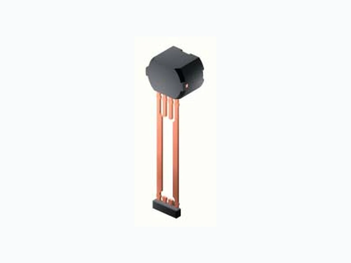
The ATS642LSH is an optimized Hall effect sensing integrated circuit and magnet combination that provides a user-friendly solution for true zero-speed digital gear-tooth sensing in two- wire applications. The sensor consists of a single-shot molded plastic package that includes a samarium cobalt magnet, a pole piece, and a Hall effect IC that has been optimized to the magnetic circuit. This small package, with optimized two-wire leadframe, can be easily assembled and used in conjunction with a wide variety of gear shapes and sizes. The integrated circuit incorporates a dual element Hall effect sensor and signal processing that switches in response to differential magnetic signals created by ferrous gear teeth. The circuitry contains a sophisticated digital circuit to reduce magnet and system offsets, to calibrate the gain for air gap independent switchpoints, and to achieve true zero-speed operation. Signal optimization occurs at power-up through the combination of offset and gain adjust and is maintained throughout the operating time with the use of a running mode calibration. The running mode calibration allows immunity to environmental effects such as microoscillations of the target or sudden air gap changes. The regulated current output is configured for two wire applications and the sensor is ideally suited for obtain- ATS642LSH-DS, Rev. 1 Features and Benefits ▪ Running mode calibration for continuous optimization ▪ Single chip IC for high reliability ▪ Internal current regulator for 2-wire operation ▪ Small mechanical size (8 mm diameter × 5.5 mm depth) ▪ Precise duty cycle signal over operating temperature range ▪ Large operating air gaps ▪ Automatic Gain Control (AGC) for air gap independent switchpoints ▪ Automatic Offset Adjustment (AOA) for signal processing optimization ▪ True zero-speed operation ▪ Undervoltage lockout ▪ Wide operating voltage range Two-Wire True Zero Speed Miniature Differential Peak-Detecting Gear Tooth Sensor with Continuous Calibration Continued on the next page… Package: 4-pin Module (suffix SH) Functional Block Diagram Not to scale ATS642LSH VCC Automatic Offset Control AOA DAC Hall Amplifier AGC DAC Gain Tracking DAC Peak Hold Gain Control Internal Regulator Test Signals GND Test
Two-Wire True Zero Speed Miniature Differential Peak-Detecting Gear Tooth Sensor with Continuous CalibrationATS642LSH 2Allegro MicroSystems, Inc.
115 Northeast Cutoff
Worcester, Massachusetts 01615-0036 U.S.A. Absolute Maximum Ratings Characteristic Symbol Notes Rating Unit Supply Voltage V CC 28 V Reverse_Supply Voltage V RCC –18 V Operating Ambient Temperature T A Range L –40 to 150 ºC Maximum Junction Temperature T J(max) 165 ºC Storage Temperature T stg –65 to 170 ºC Selection Guide Part Number I CC Typical Packing* ATS642LSHTN-I1-T 6.0 Low to 14.0 High mA Tape and reel, 13-inch reel 800 pieces/reelATS642LSHTN-I2-T 7.0 Low to 14.0 High mA *Contact Allegro® for additional packing options ing speed and duty cycle information in ABS (antilock braking systems). The 1.5 mm Hall element spacing is optimized for fine pitch gear-tooth-based configurations. The package is lead (Pb) free, with 100% matte tin leadframe plating. Description (continued) Pin-out Diagram Terminal List Number Name Function
1 VCC Connects power supply to chip
2 NC No connection
3 Test pin Float or tie to GND
4 GND Ground terminal24 31
Two-Wire True Zero Speed Miniature Differential Peak-Detecting Gear Tooth Sensor with Continuous CalibrationATS642LSH 3Allegro MicroSystems, Inc. Worcester, Massachusetts 01615-0036 U.S.A. OPERATING CHARACTERISTICS using reference target 60-0, TA and VCC within specification, unless otherwise noted Characteristic Symbol Test Conditions Min. Typ. 1 Max. Units
ELECTRICAL CHARACTERISTICS
2 VCC Operating; TJ < 165 °C 4.0 – 24 V Undervoltage Lockout V CC(UV) VCC 0 → 5 V and 5 → 0 V – – 4.0 V Supply Zener Clamp Voltage V Z ICC = ICC(max) + 3 mA; TA = 25°C 28 – – V Supply Zener Current I Z Test conditions only; VZ = 28 V – – ICC(max)+ 3 mA mA Supply Current ICC(Low) ATS642LSH-I1 4.0 6.0 8.0 mA ATS642LSH-I2 5.9 7.0 8.4 mA ICC(High) ATS642LSH-I1 12.0 14.0 16.0 mA ATS642LSH-I2 11.8 14.0 16.8 mA Supply Current Ratio ICC(High)/ ICC(Low) Ratio of high current to low current 1.85 – 3.05 – Reverse Battery Current I RCC VRCC = –18 V – – –5 mA POWER-ON STATE CHARACTERISTICS Power-On State
3 POS t > t PO –I CC(High) ––
Power-On Time4 tPO Target gear speed < 100 rpm – 1 2 ms OUTPUT STAGE Output Slew Rate 5 dI/dt R LOAD = 100 Ω, CLOAD = 10 pF – 10 – mA/ μs Continued on the next page.
Two-Wire True Zero Speed Miniature Differential Peak-Detecting Gear Tooth Sensor with Continuous CalibrationATS642LSH 4Allegro MicroSystems, Inc. Worcester, Massachusetts 01615-0036 U.S.A. OPERATING CHARACTERISTICS (continued) using reference target 60-0, TA and VCC within specification, unless otherwise noted Characteristic Symbol Test Conditions Min. Typ. 1 Max. Units SWITCHPOINT CHARACTERISTICS Rotation Speed S ROT Reference Target 60-0 0 – 8,000 rpm Analog Signal Bandwidth BW Equivalent to f – 3 dB 20 40 – kHz Operate Point B OP Transitioning from ICC(High) to ICC(Low); positive peak referenced; AG < AGMAX – 120 – mV Release Point B RP Transitioning from ICC(Low) to ICC(High); negative peak referenced; AG < AGMAX – 120 – mV CALIBRATION Initial Calibration C I Quantity of rising output (current) edges required for accurate edge detection – – 3 Edge DAC CHARACTERISTICS Allowable User-Induced Differential Offset Output switching only; may not meet datasheet speci- fi cations – ±60 – G FUNCTIONAL CHARACTERISTICS6 Operational Air Gap Range7 AG ∆DC within specification 0.5 – 2.75 mm Maximum Operational Air Gap Range AGOP(max) Output switching (no missed edges); ∆DC not guaran- teed ––3 m m Duty Cycle Variation ∆DC Wobble < 0.5 mm; Typical value at AG = 1.5 mm, for max., min., AG within specification 41 – 61 % Duty Cycle Pitch Variance8 EDC AG = 1.5 mm – ±1.5 – % Operating Signal Range9 Sig Operating within specification 30 – 1000 G Minimum Operating Signal Sig OP(min) Output switching (no missed edges); ∆DC not guaran- teed 20 – – G 1Typical values are at TA = 25°C and VCC = 12 V. Performance may vary for individual units, within the specified maximum and minimum limits. 2Maximum voltage must be adjusted for power dissipation and junction temperature; see Power Derating section. 3Please refer to Sensor Operation section, page 13. 4Power-On Time includes the time required to complete the internal automatic offset adjust. The DACs are then ready for peak acquisition. 5dI is the difference between 10% of ICC(Low) and 90% of ICC(High), and dt is time period between those two points. Note: di/dt is dependent upon the value of the bypass capacitor, if one is used. 6Functional characteristics valid only if magnetic offset is within the specified range for Allowable User Induced Differential Offset. 7AG is dependent on the available magnetic field. The available field is dependent on target geometry and material, and should be independently char- acterized. The field available from the reference target is given in the reference target parameter section of the datasheet. 8EDC represents the difference between consecutive duty cycles, DC(n) - DC(n-1); Mean ± 3-sigma. 9In order to remain in specification, the magnetic gradient must induce an operating signal greater than the minimum value specified. This includes the effect of target wobble.
Two-Wire True Zero Speed Miniature Differential Peak-Detecting Gear Tooth Sensor with Continuous CalibrationATS642LSH 5Allegro MicroSystems, Inc. Worcester, Massachusetts 01615-0036 U.S.A. REFERENCE TARGET, 60-0 (60 Tooth Target) Characteristics Symbol Test Conditions Typ. Units Symbol Key Outside Diameter D o Outside diameter of target 120 mm Do ht F Air Gap Branded Face of Sensor t tv Face Width F Breadth of tooth, with respect to sensor 6m m Angular Tooth Thickness t Length of tooth, with respect to sensor 3 deg Angular Valley Thickness t v Length of valley, with respect to sensor 3 deg Tooth Whole Depth h t 3m m Material Low Carbon Steel – – Reference Gear Magnetic Gradient Amplitude With Reference to Air Gap Air Gap (mm) Peak-to-Peak Differential B (G) 100 200 300 400 500 600 700 800 11 . 5 20.5 2.5 3 Reference Gear Magnetic Profile Two Tooth-to-Valley Transitions -500 -400 -300 -200 -100 100 200 300 400 500 Gear Rotation (°) Differential B* (G) 02468 1 0 1 2 0.50 (mm) Air Gap 0.50 mm AG 3.00 mm AG 0.75 1.00 1.25 1.50 1.75 2.00 2.25 2.50 2.75 3.00 Reference Target 60-0 of Sensor Branded Face
Two-Wire True Zero Speed Miniature Differential Peak-Detecting Gear Tooth Sensor with Continuous CalibrationATS642LSH 6Allegro MicroSystems, Inc. Worcester, Massachusetts 01615-0036 U.S.A. Characteristic Data I1 Trim Supply Current (High) versus Ambient Temperature (ATS642-I1) -50 0 50 100 150 TA (°C) ICC(HIGH) (mA) VCC (V) Supply Current (High) versus Supply Voltage (ATS642-I1) 0 5 10 15 20 25 VCC (V) ICC(HIGH) (mA) TA (°C) Supply Current (Low) versus Ambient Temperature (ATS642- I1) -50 0 50 100 150 TA (°C) ICC(LOW) (mA) Vcc (V) Supply Current (Low) versus Supply Voltage (ATS642-I1) 05 1 0 1 5 2 0 2 5 VCC (V) ICC(LOW) (mA) TA (°C) -40 150 -40 150
Two-Wire True Zero Speed Miniature Differential Peak-Detecting Gear Tooth Sensor with Continuous CalibrationATS642LSH 7Allegro MicroSystems, Inc. Worcester, Massachusetts 01615-0036 U.S.A. Duty Cycle versus Air Gap* AG (mm) DC (%) TA (°C) -40 150 Duty Cycle versus Ambient Temperature –50 0 50 100 150 TA (°C) DC (%) AG (mm) 0.5 1.5 2.75 Duty Cycle Variance versus Air Gap Mean ± 3 Sigma, 25°C AG (mm) EDC (%) *The trend of duty cycle versus air gap is driven by the actual magnetic profile of the target (see figure on page 5).
Two-Wire True Zero Speed Miniature Differential Peak-Detecting Gear Tooth Sensor with Continuous CalibrationATS642LSH 8Allegro MicroSystems, Inc. Worcester, Massachusetts 01615-0036 U.S.A. ΔTEAGIN (mm) ΔTEAGOUT (mm) Allowable Air Gap Movement from TEAGCAL -0.2 0.2 0.4 0.6 0.8 1.0 1.2 Characteristic Allowable Air Gap Movement 60-0 (60 Tooth Target) The colored area in the chart above shows the region of allow- able air gap movement within which the sensor will continue output switching. The output duty cycle is wholly dependent on the target’s magnetic signature across the air gap range of move- ment, and may not always be within specification throughout the entire operating region (to AG (OPmax)). The axis parameters for the chart are defined in the draw- ings below. As an example, assume the case where the air gap is allowed to vary from from the nominal installed air gap (TEAG CAL , panel a) within the range defined by an increase of TEAGOUT = 0.35 mm (shown in panel b), and a decrease of TEAGIN = 0.65 mm (shown in panel c). This case is plotted with an “x” in the chart above. For more information on these figures and the calculations used to generate them, please refer to the Applications Note Determining Allowable Air Gap Variation for the ATS642. TEAGINSensor Sensor TEAGOUT (a) Sensor TEAGCAL (b) (c)
Two-Wire True Zero Speed Miniature Differential Peak-Detecting Gear Tooth Sensor with Continuous CalibrationATS642LSH 9Allegro MicroSystems, Inc. Worcester, Massachusetts 01615-0036 U.S.A. THERMAL CHARACTERISTICS may require derating at maximum conditions, see application information Characteristic Symbol Test Conditions* Value Units Package Thermal Resistance RθJA Single-layer PCB with copper limited to solder pads 126 ºC/W Two-layer PCB with 3.8 in.2 of copper area on each side con- nected with thermal vias and to device ground pin 84 ºC/W *Additional information is available on the Allegro Web site. 20 40 60 80 100 120 140 160 180 Temperature (ºC) Maximum Allowable VCC (V) Power Derating Curve (RθJA = 126 ºC/W) (RθJA = 84 ºC/W) VCC(min) VCC(max) 100 200 300 400 500 600 700 800 900 1000 1100 1200 1300 1400 1500 1600 1700 1800 1900 20 40 60 80 100 120 140 160 180 Temperature (°C) Power Dissipation, PD (mW) Maximum Power Dissipation, PD(max) θJA = 126 ºC/ θJA = 84 ºC/W
10Allegro MicroSystems, Inc. Worcester, Massachusetts 01615-0036 U.S.A. a proprietary BiCMOS process. tion is reversed, then the output polarity inverts. Figure 1. Relative motion of the target is detected by the dual Hall ele- ments mounted on the Hall IC. Figure 2. This left-to-right (pin 1 to pin 4) direction of target rotation tion inverts the output signal polarity. Figure 4: Voltages profiles for high side and low side two-wire sensing. Figure 3. Output Profile of a ferrous target for the polarity indicated in
11Allegro MicroSystems, Inc. Worcester, Massachusetts 01615-0036 U.S.A. to achieve true zero-speed operation. Figure 5. Automatic Gain Control (AGC). The AGC function corrects for
Two-Wire True Zero Speed Miniature Differential Peak-Detecting Gear Tooth Sensor with Continuous CalibrationATS642LSH 12Allegro MicroSystems, Inc. Worcester, Massachusetts 01615-0036 U.S.A. Power Supply Protection The device contains an on-chip regulator and can operate over a wide VCC range. For devices that need to operate from an unregulated power supply, transient protection must be added externally. For applications using a regulated line, EMI/RFI pro- tection may still be required. Contact Allegro Microsystems for information on the circuitry needed for compliance with various EMC specifications. Refer to figure 7 for an example of a basic application circuit. Undervoltage Lockout When the supply voltage falls below the undervoltage lockout voltage, VCC(UV), the device enters Reset, where the output state returns to the Power-On State (POS) until sufficient VCC is sup- plied. ICC levels may not meet datasheet limits when VCC < VCC(min). Assembly Description This sensor is integrally molded into a plastic body that has been optimized for size, ease of assembly, and manufacturability. High operating temperature materials are used in all aspects of construction. Diagnostics The regulated current output is configured for two-wire appli- cations, requiring one less wire for operation than do switches with the more traditional open-collector output. Additionally, the system designer inherently gains diagnostics because there is always output current flowing, which should be in either of two narrow ranges, shown in figure 8 as I CC(High) and ICC(Low). Any current level not within these ranges indicates a fault condi- tion. If I CC > ICC(High)max, then a short condition exists, and if ICC < ICC(low)min, then an open condition exists. Any value of ICC between the allowed ranges for ICC(High) and ICC(Low) indicates a general fault condition. Figure 7: Typical Application Circuit ATS642 VCC GND 0.01 µF ECU Pins 2 and 3 floating R 100 Ω SENSE CBYP Figure 8: Diagnostic Characteristics of Supply Current Values ICC(High)max ICC(High)min Range for Valid ICC(HIGH) Range for Valid ICC(LOW) ICC(Low)max ICC(Low)min +mA Short Fault Open
Two-Wire True Zero Speed Miniature Differential Peak-Detecting Gear Tooth Sensor with Continuous CalibrationATS642LSH 13Allegro MicroSystems, Inc. Worcester, Massachusetts 01615-0036 U.S.A. Sensor Operation Each operating mode is described in detail below. Power-On When power (VCC > VCCMIN) is applied to the device, a short period of time is required to power the various portions of the IC. During this period, the ATS642 will power-on in the high current state, I CC(High). After power on, there are conditions that could induce a change in the output state. Such an event could be caused by thermal transients, but would require a static applied magnetic field, proper signal polarity, and particular direction and magnitude of internal signal drift. Initial Offset Adjust The sensor intially cancels the effects of chip, magnet, and installation offsets. Once offsets have been cancelled, the digital tracking DAC is ready to track the signal and provide output switching. The period of time required for both Power-On and Initial Offset Adjust is defined as the Power-On Time. Calibration Mode The calibration mode allows the sensor to automatically select the proper signal gain and continue to adjust for offsets. The AGC is active, and selects the optimal signal gain based on the amplitude of the V PROC signal. Following each adjustment to the AGC DAC, the Offset DAC is also adjusted to ensure the internal analog signal is properly centered. During this mode, the tracking DAC is active and output switch- ing occurs, but the duty cycle is not guaranteed to be within specification. Running Mode After the Initial Calibration period, CI, establishes a signal gain, the device moves to Running mode. During Running mode, the sensor tracks the input signal and gives an output edge for every peak of the signal. AOA remains active to compensate for any offset drift over time. The ATS642 incorporates a novel algorithm for adjusting the signal gain during Running mode. This algorithm is designed to optimize the V PROC signal amplitude in instances where the magnetic signal “seen” during the calibration period is not repre- sentative of the amplitude of the magnetic signal for the installed sensor air gap (see figure 9). Sensor Electrical Output, IOUT Internal Differential Signal, V PROC BRP BOP BOP BRP 1 2 3 4 5 Figure 9: Operation of Running Mode Gain Adjust. Position 1. The device is initially powered-on. Self-calibration occurs. Position 2. Small amplitude oscillation of the target sends an erroneously small differential signal to the sensor. The ampli- tude of V PROC is greater than the switching hysteresis (BOP and BRP), and the device output switches. Position 3. The calibration period completes on the third rising output edge, and the device enters Running mode. Position 4. True target rotation occurs and the correct magnetic signal is generated for the installation air gap. The estab- lished signal gain is too large for the target’s rotational magnetic signal at the given air gap. Position 5. Running Mode Calibration corrects the signal gain to an optimal level for the installation air gap.
Two-Wire True Zero Speed Miniature Differential Peak-Detecting Gear Tooth Sensor with Continuous CalibrationATS642LSH 14Allegro MicroSystems, Inc. Worcester, Massachusetts 01615-0036 U.S.A. Power Derating The device must be operated below the maximum junction temperature of the device, T J(max). Under certain combinations of peak conditions, reliable operation may require derating sup- plied power or improving the heat dissipation properties of the application. This section presents a procedure for correlating factors affecting operating T J. (Thermal data is also available on the Allegro MicroSystems Web site.) The Package Thermal Resistance, RJA, is a figure of merit sum- marizing the ability of the application and the device to dissipate heat from the junction (die), through all paths to the ambient air. Its primary component is the Effective Thermal Conductivity, K, of the printed circuit board, including adjacent devices and traces. Radiation from the die through the device case, R JC, is relatively small component of RJA. Ambient air temperature, TA, and air motion are significant external factors, damped by overmolding. The effect of varying power levels (Power Dissipation, PD), can be estimated. The following formulas represent the fundamental relationships used to estimate T J, at PD. PD = VIN × IIN (1) T J = TA + ΔT (3) For example, given common conditions such as: TA= 25°C, VCC = 12 V, ICC = 4 mA, and RJA = 140 °C/W, then: P D = VCC × ICC = 12 V × 4 mA = 48 mW T = PD × RJA = 48 mW × 140 °C/W = 7°C A worst-case estimate, PD(max), represents the maximum allow- able power level (VCC(max), ICC(max)), without exceeding TJ(max), at a selected RJA and TA. Example: Reliability for VCC at TA = 150°C, package SH (I1 trim), using minimum-K PCB Observe the worst-case ratings for the device, specifically: RJA = 126°C/W, TJ(max) = 165°C, VCC(max) = 24 V , and ICC(max) = 16 mA. Calculate the maximum allowable power level, PD(max). First, invert equation 3: Tmax = TJ(max) – TA = 165 °C – 150 °C = 15 °C This provides the allowable increase to TJ resulting from internal power dissipation. Then, invert equation 2: PD(max) = Tmax ÷ RJA = 15°C ÷ 126 °C/W = 119 mW Finally, invert equation 1 with respect to voltage: VCC(est) = PD(max) ÷ ICC(max) = 119 mW ÷ 16 mA = 7 V The result indicates that, at TA, the application and device can dissipate adequate amounts of heat at voltages ≤VCC(est). Compare VCC(est) to VCC(max). If VCC(est) ≤ VCC(max), then reli- able operation between VCC(est) and VCC(max) requires enhanced RJA. If VCC(est) ≥ VCC(max), then operation between VCC(est) and VCC(max) is reliable under these conditions.
Two-Wire True Zero Speed Miniature Differential Peak-Detecting Gear Tooth Sensor with Continuous CalibrationATS642LSH 15Allegro MicroSystems, Inc. Worcester, Massachusetts 01615-0036 U.S.A. Package SH Module 0.71±0.05 1.00±0.10 0.60±0.10 24.65±0.10 13.10±0.10
1.0 REF
1.60±0.10 1.27±0.10 5.50±0.10 5.50±0.05 8.00±0.05 5.80±0.05 1.70±0.10 24 31 A A B D For Reference Only, not for tooling use (reference DWG-9003) Dimensions in millimeters A B C C D Dambar removal protrusion (16X) Metallic protrusion, electrically connected to pin 4 and substrate (both sides) Thermoplastic Molded Lead Bar for alignment during shipment Active Area Depth 0.43 mm REF Branded Face Standard Branding Reference View = Supplier emblem L = Lot identifier N = Last three numbers of device part number Y = Last two digits of year of manufacture W = Week of manufacture LLLLLLL YYWW NNN Branding scale and appearance at supplier discretion 0.38 +0.06 –0.04 F E F F E 0.75 E2E1 0.75 Hall elements (E1, E2); not to scale
Two-Wire True Zero Speed Miniature Differential Peak-Detecting Gear Tooth Sensor with Continuous CalibrationATS642LSH 16Allegro MicroSystems, Inc. Worcester, Massachusetts 01615-0036 U.S.A. Copyright ©2004-2009, Allegro MicroSystems, Inc. The products described herein are manufactured under one or more of the following U.S. patents: 5,045,920; 5,264,783; 5,442,283; 5,389,889; 5,581,179; 5,517,112; 5,619,137; 5,621,319; 5,650,719; 5,686,894; 5,694,038; 5,729,130; 5,917,320; and other patents pending. Allegro MicroSystems, Inc. reserves the right to make, from time to time, such de par tures from the detail spec i fi ca tions as may be required to per- mit improvements in the per for mance, reliability, or manufacturability of its products. Before placing an order, the user is cautioned to verify that the information being relied upon is current. Allegro’s products are not to be used in life support devices or systems, if a failure of an Allegro product can reasonably be expected to cause the failure of that life support device or system, or to affect the safety or effectiveness of that device or system. The in for ma tion in clud ed herein is believed to be ac cu rate and reliable. How ev er, Allegro MicroSystems, Inc. assumes no re spon si bil i ty for its use; nor for any in fringe ment of patents or other rights of third parties which may result from its use. For the latest version of this document, visit our website: www.allegromicro.com