

 Download PDF
DSA NKK
Document overview
- PDF pages: 6
Technical content
Page 1
Distinctive Characteristics
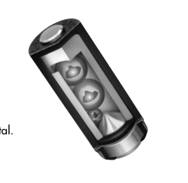
DSA
Environmentally friendly, contains no mercury.
High contact reliability due to sealed body.
The switch is triggered when tilted beyond ±10° of the horizontal.
PCB adaptor available as an accessory.
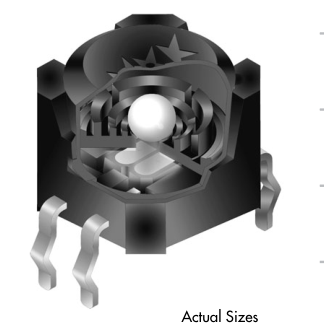
DSB
Photo interrupter, rather than contacts, ensures high reliability. 1 million operations minimum.
Sealed construction for protection from environmental elements, including hydrogen sulfide, sulfur dioxide, and nitrogen hydroxide. Terminals are made of ammonia-resistant materials.
Totally sealed body allows process compatibility for time-
K
and money-saving automatic soldering and cleaning.
Space-saving compact dimensions allow high density mounting.
Internal steel ball movement allows functionality of 360° circumference rotation.
DSA
The DSB series switch is well-suited to meet product safety concerns due to normally closed (on) status.
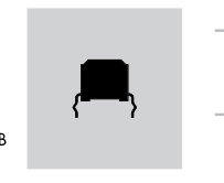
Crimped terminals ensure secure mounting and prevent dislodging during wave soldering.
The switch is triggered when tilted beyond ±30° of the horizontal.
DSB
K3
Page 2
DSA SWITCH PART NUMBER & DESCRIPTION
SPST ON – OFF
Sealed Body
DSA01
DSA SWITCH SPECIFICATIONS
Mechanical & Electrical Specifications Single Pole Single Throw ON – OFF
Poles and Circuits:
ON Angle = 10° ~ 170°; OFF Angle = 190° ~ 350°
Operating Range: Resistive Load:
0.1A @ 12V DC 100 milliohms maximum
Contact Resistance:
50 megohms minimum @ 250V DC
Insulation Resistance:
250V AC for 1 minute minimum between terminals
Dielectric Strength:
100,000 operations minimum
Mechanical Life:
100,000 operations minimum
Electrical Life:
Materials & Finishes
Housing:
PBT Nitrile Butadiene Rubber
Rubber Rings:
Brass with Silver Plating
Contact Balls:
Brass with Silver Plating
Terminals:
Environmental Specifications
K
–10°C ~ +70°C (+14°F ~ +158°F)
Operating Temperature Range:
–25°C ~ +85°C (–13°F ~ +185°F)
Storage Temperature Range: Contact Bounce (for reference):
500ms maximum 90% humidity for 96 hours @ 40°C (104°F)
Humidity:
Frequency range 10Hz ~ 500Hz for 2 hours; 2 directions; Acceleration: 0.2G
Vibration (for reference):
- Do not install switch near vibration source.
Notes:
- Terminals should not be exposed to liquid.
Processing for AT094 PCB Adaptor
Wave Soldering: See Profile A in Supplement section.
Soldering (with PCB Mount Holder):
Manual Soldering: See Profile B in Supplement section.
Hand clean locally using alcohol based solution.
Automated Cleaning:
K4
Page 3
DSA SWITCH SPECIFICATIONS (CONTINUED)
Operating Range
Cross Section
UP ON
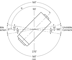
Unstable Connection
OFF
Allow 500ms settling time between states.
DOWN
TYPICAL SWITCH DIMENSIONS
Part No.
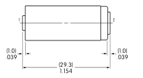
This End
(4.9) Dia .193
(7.4) Dia
(11.5) Dia
.291
.453
Terminal numbers are not on the switch.
DSA01
OPTIONAL ADAPTOR
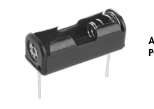
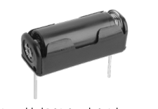
AT094
Materials:
PCB Adaptor for DSA01
Holder: Polypropylene Spring: Spring Steel with Nickel Plating PC Pins: Brass with
K
Nickel Plating
Assembled DSA Switch & Adaptor
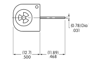
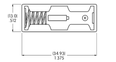
Dia Typ
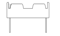
(1.02) DiaTyp .040
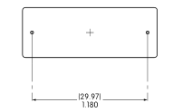
(29.97) 1.180
PCB Footprint
K5
Page 4
DSB SWITCH PART NUMBERS & DESCRIPTION
ON-OFF Status
ON-OFF Status
Straight
Right Angle
PC Terminals
PC Terminals
DSBA1P
DSBA1H
DSB SWITCH SPECIFICATIONS
Absolute Maximum Ratings Temperature at 25°C
Symbol
Rating
Unit
| Input | Forward Current I 50 mA F |
| Reverse Voltage V 5 V R | |
| Power Dissipation P 75 mW D | |
| Output | Collector-Emitter Voltage V 30 V CEO |
| Emitter-Collector Voltage V 3 V ECO | |
| Collector Current I 20 mA C | |
| Collector Power Dissipation P 50 mW C |
100
mW
Total Power Dissipation
Ptot
Mechanical Specifications
1,000,000 operations minimum
Mechanical Life:
1,000,000 operations minimum using applicable circuit
Electrical Life:
Materials & Finishes
Glass fiber reinforced polyamide (UL94V-0 flammability rating)
Housing:
K
Glass fiber reinforced polyamide (UL94V-0 flammability rating) Base:
Phosphor bronze with tin plating
Terminals:
Environmental Specifications
–25°C ~ +80°C (–13°F ~ +176°F)
Operating Temperature Range:
–30°C ~ +85°C (–22°F ~ +185°F)
Storage Temperature Range:
85% humidity for 500 hours @ +85°C (+185°F)
Humidity:
10Hz with peak-to-peak amplitude of 10mm traversing the frequency range
Vibration:
& returning in 1 minute; 3 right angled directions for 500,000 cycles
100G (981m/s2) acceleration (tested in 6 right angled directions, with
Shock:
5 shocks in each direction)
- Prevent exposure to magnetic fields.
Notes:
- Do not install switch near vibration source.
K6
Page 5
DSB SWITCH SPECIFICATIONS (CONTINUED)
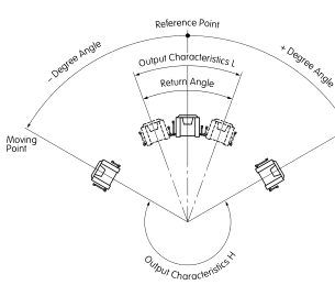
Operating Characteristics
Operating Angle
Return Angle
±30° to ±60°
Circuit Characteristics (ON-OFF)
Minimum 10°
Output VOL VOH
Output VOH VOL
Output Characteristics VOL with Photo transistor ON: 1.0V maximum (horizontal)
Output Characteristics VOH with Photo transistor OFF: 4.0V minimum (inclined at an angle of –60° minimum)
Output Characteristics
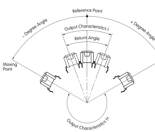
Moving
Moving
Point
Point
Straight PC
Right Angle PC
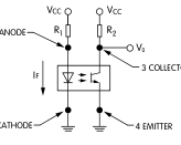
Circuit Design Considerations
K
VCC = 5V R2 = 100kΩ IF = 19mA (VCC = 5V, R1 = 200Ω) VF of the LED Maximum = 1.3V
PCB Processing
Wave Soldering: See Profile A in Supplement section.
Soldering :
Manual Soldering: See Profile A in Supplement section.
Use alcohol based solution at 50°C maximum. Do not submerge over
Automated Cleaning:
2.0” (5.0cm) for 1 minute maximum. Do not use organic solvents.
K7
Page 6
MOUNTING OPTIONS
PCB
PCB
PCB mounting option for Straight PC
PCB mounting option for Right Angle PC
Install switch at an angle less than ±3° from the mounting surface.
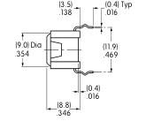
TYPICAL SWITCH DIMENSIONS
Straight PC
(1.3) Dia Typ (5.1)
.051 .201
(5.1) .201
2 Cathode
3 Collector
3 2
(11.9)
(10.0)
.469
.394
4 1
1 Anode 4 Emitter
(0.9)
(3.1)
.035
.122
(9.5)
(3.1)
.374
.122
Terminal numbers are on bottom of switch.
DSBA1P
Right Angle PC
K
(8.8) .346 (7.7) .303 (0.4)
(9.0)Dia
.016
.354
(3.1)
2 Cathode
.122 1 Anode
(5.1)
(9.5)
.201
.374
4 Emitter
3 Collector
(11.9) (1.3) DiaTyp
(3.5)
(0.4)
.051 .469
.016
.138
(3.1) .122 (1.5)
(0.9) Typ
(10.0)
.059
.035
.394
(5.1)
(11.9)
(11.9)
.201
.469
.469
Terminal numbers are on bottom of switch.
DSBA1H
K8