

 Download PDF
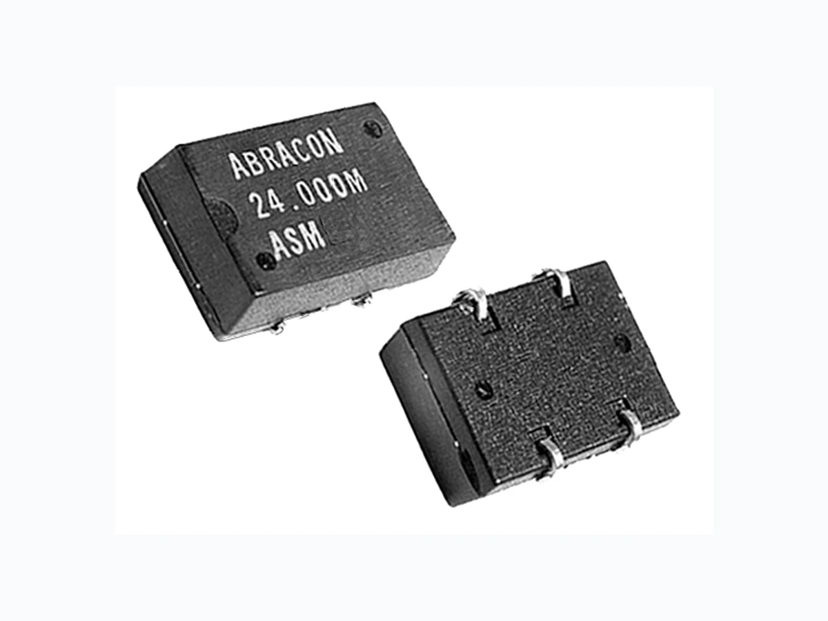
ASM ABRACON
Document overview
- PDF pages: 1
Technical content
Page 1

14.0 x 8.95 x 4.7 mm
FEATURES:
- Plastic molded SMD.
- Industry standard J-leaded terminals.
- Tristate Enable/Disable.
- HCMOS and TTL compatible.
- Extended temperature -40°C to +85°C option.
APPLICATIONS:
- Wide range of applications in dialing communication equipment, AV / OA equipment, Measuring equipment. S ST TA AN ND DA AR RD
S SP PE EC CI IF FI IC CA AT TI IO ON NS
STANDARD
DSPECIFICATIONS
S
Frequency Range
3.5MHz - 25 MHz
PARAMETERS
ASM
ASMT
ASMH
PARAMETERS
SPECIFICATIONS
Operation Mode
Fundamental, AT
STANDARD SPECIFICATION
S
STANDARD SPECIFICATION
S
Frequency Range
(Fo)
1.00MHz - 70.000MHz
Operating Temperature
-10°C to + 60° C (See Options) -55°C to + 125° Cance @ 25°C max. (See
Operating Tempature (TOPR) 0°C to +70°C (See Options) Storage Temperature
-40°C to +85°C
Options) Storage Temperature (TSTO) Frequency Stability over Temp.
±50 ppm max. (See Options)
(∆F/ Fo)
Frequency Stability
±100ppm max. (See Options) 200 Ω for 3.5 MHz < F < 4.0 MHz
Equivalent Series Resistance Supply Voltage
(Vdd)
5Vdc ±10% 150 Ω for 4.0 MHz < F < 6.0 MHz
(ESR) Maximum
25mA max. (F< 30MHz); 35mA max. (F> 30MHz)
Input Current
(Idd)
100 Ω for 6.0 MHz < F < 10.0 MHz 45/55% max. for F <_ 10 MHz 80 Ω for 10 MHz < F < 14.0 MHz
Duty Cycle or Symmetry
40 / 60% max. for F > 10 MHz (See Options & Note 1) 50 Ω for 14 MHz < F <_ 25 MHz 8ns max. (F < 40MHz) ; 6ns max. (F > 40MHz)
Rise and Fall Times (TR / TF) Shunt Capacitance C0
7 pF max. 10TTL max., 50pF max. (F < 50MHz); 15pF (F > 50MHz)
Output Load Load Capacitance CL
16pF (See Option)
(VOH) 2.4Vdc min. (TTL) ; 0.9\*Vdd min.(HCMOS)
100µΩ max.
Output Voltage Drive Level
(VOL) 0.4Vdc max. (TTL) ; 0.1\*Vdd max.(HCMOS)
Aging @ 25° C First Year
± 5 ppm max. 10TTL (for F <_ 50 MHz)
10TTL
15 pF (50pF max.)
Start-up Time
(TOSC)
10 ms max.
15 pF
5TTL (for F> 50 MHz)
15 pF (30pF max.
100 ns max. “1” or Open: Oscillation
VIH >_ 2.0V
Output Disable /
(50 pF max.)
for F > 50 MHz)
“0”: Output disabled in high impedance (HiZ) VIL < 0.8V
Enable Disabled current (IDIS) 0.9 \* Vdd min.
28mA max 2.4 Vdc min.
0.9 \* Vdd min.
0.4 Vdc max.
0.4 Vdc max.
0.1 \* Vdd max.
Aging ±5ppm / Year max.
Note 1: Option -S (Symmetry level measured at 1/2 Vdd for HCMOS, and at 1.4 Vdc for TTL. Note 2: Pin 1 has internal pull-up resistor which allows pin 1 to be left floating (enable high) Connect a By-Pass capacitor 0.01 µF between Vdd and GND.
Test circuit, waveforms, see appendix B. Recommended handling, see appendix F. Environmental and mechanical specifications, see appendix C. Group 2. Marking, see appendix G. Tape and Reel, see appendix H.(1,000 pcs./ reel). Application notes, see appendix, A. Reflow profile, see appendix E.
ORDERING OPTIONS
ORDERING OPT ONS
ORDERING OPT ONS
Dimensions: Inches (mm)
ASM - Frequency - Temperature - Frequency Stability - Duty Cycle
- Packaging
PIN
FUNCTION
-S for 45 /55% @ 1/2 Vdd
NUMBER
- T
XX.XXXXX MHz
-D for -10°C to + 60°C
-S1 for 45 /55% @ 1.4 Vdc
(Tape & Reel)
1 1 Tristate E/D Tristate E/D
-E for -20°C to + 70°C
7 2 GND / Case GND / Case
-F for -30°C to + 70°C
-R for ± 25ppm max.
-N for -30°C to + 85°C
8 3 Output Output
-K for ± 30ppm max.
-L for -40°C to + 85°C
14 4 Vdd Vdd
-H for ± 35ppm max. -C for ± 50ppm max.
ABRACON
NOTE: Left blank if standard • All specifications and markings subject to change without notice
®
ABRACON IS
29 Journey • Aliso Viejo, CA 92656 • USA
ISO 9001 / QS 9000
(949) 448-7070 • FAX: (949) 448-8484
CERTIFIED
E-MAIL: abinfo@abracon.com • INTERNET ADDRESS: www.abracon.com