
ASGPDF254.A TEMPATRON
Document overview
- Manufacturer or author: Provided By www.digicamel.com(free datasheet download site)
- PDF pages: 31
Technical content
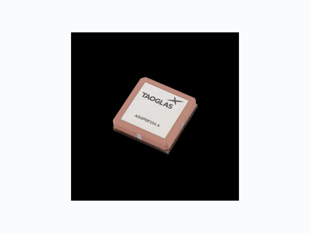
Active GNSS Surface Mount Patch Part No: ASGPDF254.A
Description
GPS/GLONASS/BeiDou/Galileo SMD Dual Feed Active Patch with Embedded Active Circuitry Features: Embedded Dual-Feed Patch for Lowest Axial Ratio Covers Bands: - GPS L1C - GLONASS L1 - Galileo E1 - BeiDou B1 SMD Antenna – No Cable and Connector Required Dimension: 25*25*6.5mm Designed for a 70x70mm Ground plane RoHS & Reach Compliant
www.taoglas.com SPE-23-8-190-A 1. Introduction 2 2. Specification 3 3. Antenna Characteristics 5 4. Radiation Patterns 11 5. LNA Characteristics 15 6. Mechanical Drawing 17 7. Antenna Integration Guide 18 8. Packaging 24 9. Solder Reflow Profile 26 Changelog Taoglas makes no warranties based on the accuracy or completeness of the contents of this document and reserves the right to make changes to specifications and product descriptions at any time without notice. Taoglas reserves all rights to this document and the information contained herein. Reproduction, use or disclosure to third parties without express permission is strictly prohibited.
www.taoglas.com SPE-23-8-190-A 1. Introduction The Taoglas ASGPDF254.A is a single band active GNSS patch covering GPS/GLONASS/BeiDou/Galileo. The ASGPDF254.A has been designed with a dual pin patch to enhance performance by improving multipath rejection so signals can be received and sent more clearly. With hidden active circuitry embedded between the ceramic patch and PCB base, it has been designed to allow the user to mount it directly onto their device PCB. This eliminates the need for using a cable and connector thus speeding up the assembly process by allowing successfully solder surface mount components to a circuit board via the SMD process. The ASGPDF254.A measures 25 x 25 x 6.45mm and is optimized for a ground plane size of 70*70mm being required for operation however smaller ground planes can be used. The ASGPDF254.A also includes a two-stage LNA and a front-end SAW filter to reduce out of band noise such as from nearby cellular transceivers and this improves the probability of the wireless device passing radiated spurious emissions certification. As with many high performance Taoglas patches, the series is produced in a TS16949 automotive quality approved facility, and each patch produced is 100% tested for gain (S21) and return loss (S11) to ensure total consistency of performance. Typical Applications Include: - Wearables - Asset Tracking - Navigation Systems Taoglas also offers custom tuning service based on minimum order quantities, contact your regional Taoglas customer support team for further information.
www.taoglas.com SPE-23-8-190-A 2. Specification GNSS Frequency Bands GPS L1
1575.42 MHz
1227.6 MHz
1176.45 MHz
◼ GLONASS G1
1602 MHz
1248 MHz
1207 MHz
◼ Galileo E1
1575.24 MHz
1201.5 MHz
1278.75 MHz
◼ BeiDou B1C
1561 MHz
1207.14 MHz
1268.52 MHz
1542 MHz
QZSS (Regional) L1 1278.75e6 ◼ IRNSS (Regional) L5 GNSS Bands and Constellations
www.taoglas.com SPE-23-8-190-A Frequency (MHz) 1561 1575.42 1603 Efficiency (%) 30.3 61.8 50.7 Average Gain (dB) -5.19 -2.09 -2.95 Peak Gain (dBi) 1.23 4.36 3.55 Impedance 50 Ω Polarization Linear Radiation Pattern Directional LNA and Filter Electrical Properties Frequency (MHz) 1561 1575.42 1602 Return Loss (dB) <-10 <-10 <-10 Gain @ 3V (dB) 14.3 14.9 13.7 Noise @ 3V (dB) 2.0 1.9 2.0 DC Power Input (V) 1.8 ~ 5.5 Power consumption @3V (mA) 4.5 Outer Band Attenuation (dB) > 60 @ 617-960 MHz > 50 @ 1,710-2,170 MHz Mechanical Ceramic Dimension (mm) 25 x 25 x 6.4 Weight (g) -- Material Ceramic Environmental Operation Temperature -40°C to 85°C Humidity Non-condensing 65°C 95% RH Moisture Sensitivity Level (MSL) 3 (168 Hours) * Antenna properties were measured with the antenna mounted on 70*70mm Ground Plane.
www.taoglas.com SPE-23-8-190-A 3. Antenna Characteristics
3.1 S11 / VSWR / Return Loss Test Setup
www.taoglas.com SPE-23-8-190-A
3.2 Return Loss
3.3 VSWR
-30 -20 -10 1400 1425 1450 1475 1500 1525 1550 1575 1600 1625 1650 1675 1700 Frequency [MHz] 1.0 2.0 3.0 4.0 5.0 6.0 1400 1425 1450 1475 1500 1525 1550 1575 1600 1625 1650 1675 1700 Frequency [MHz]
www.taoglas.com SPE-23-8-190-A
3.4 Efficiency
3.5 Average Gain
10% 20% 30% 40% 50% 60% 70% 80% 90% 100% 1400 1425 1450 1475 1500 1525 1550 1575 1600 1625 1650 1675 1700 Frequency [MHz] -10.0 -8.0 -6.0 -4.0 -2.0 0.0 1400 1425 1450 1475 1500 1525 1550 1575 1600 1625 1650 1675 1700 Frequency [MHz]
www.taoglas.com SPE-23-8-190-A
3.6 Peak Gain
3.7 Axial Ratio vs Frequency
-10.0 -8.0 -6.0 -4.0 -2.0 0.0 2.0 4.0 6.0 8.0 10.0 1400 1425 1450 1475 1500 1525 1550 1575 1600 1625 1650 1675 1700 Frequency [MHz] 0.0 3.0 6.0 9.0 1400 1425 1450 1475 1500 1525 1550 1575 1600 1625 1650 1675 1700 Frequency [MHz]
www.taoglas.com SPE-23-8-190-A
3.8 Axial Ratio @1561MHz
3.9 Axial Ratio @1575MHz
0.0 3.0 6.0 9.0 -180 -120 -60 0 60 120 180 Angle [Deg] 0.0 3.0 6.0 9.0 -180 -120 -60 0 60 120 180 Angle [Deg] 0.0 3.0 6.0 9.0 -180 -120 -60 0 60 120 180 Angle [Deg] 0.0 3.0 6.0 9.0 -180 -120 -60 0 60 120 180 Angle [Deg]
www.taoglas.com SPE-23-8-190-A
3.10 Axial Ratio @1602MHz
0.0 3.0 6.0 9.0 -180 -120 -60 0 60 120 180 Angle [Deg] 0.0 3.0 6.0 9.0 -180 -120 -60 0 60 120 180 Angle [Deg]
www.taoglas.com SPE-23-8-190-A 4. Radiation Patterns
4.1 Test Setup
X Y Z
www.taoglas.com SPE-23-8-190-A
4.2 Radiation Patterns @1561MHz
XY Plane XZ Plane YZ Plane
www.taoglas.com SPE-23-8-190-A
4.3 Radiation Patterns @1575MHz
XY Plane XZ Plane YZ Plane
www.taoglas.com SPE-23-8-190-A
4.4 Radiation Patterns @1602MHz
XY Plane XZ Plane YZ Plane
www.taoglas.com SPE-23-8-190-A 5. LNA Characteristics
5.1 LNA Block Diagram
5.2 Gain
-50 -40 -30 -20 -10 1400 1425 1450 1475 1500 1525 1550 1575 1600 1625 1650 1675 1700 (dB) (MHz)
www.taoglas.com SPE-23-8-190-A
5.3 Noise Figure
5.4 Out-Of-Band Rejection
5.5 1560 1570 1580 1590 1600 1610 (dB) -60 -50 -40 -30 -20 -10 500 1000 1500 2000 2500 3000 3500 4000 4500 5000 5500 6000 (dB) (MHz)
www.taoglas.com SPE-23-8-190-A 6. Mechanical Drawing
www.taoglas.com SPE-23-8-190-A 7. Antenna Integration Guide
www.taoglas.com SPE-23-8-190-A
7.1 Schematic Symbol and Pin Definition
The circuit symbol for the antenna is shown below. The antenna has 9 pins as indicated below. Pin 1 represents the GNSS frequency bands at 1559 - 1610MHz. Pin Description
1 RF Feed
www.taoglas.com SPE-23-8-190-A
7.2 Antenna Integration
The antenna should be placed at the center of the ground plane with a length and width of 70mm. Maintaining a square symmetric ground plane shape and symmetric environment around the antenna is critical to maintaining the excellent axial ratio and phase center performance shown in this datasheet. Top Side w/ Solder Mask Top Side w/o Solder Mask
www.taoglas.com SPE-23-8-190-A
7.3 PCB Layout
The footprint and clearance on the PCB must comply with the antenna specification. The PCB layout shown in the diagram below demonstrates the antenna footprint. Topside Bottom Side
www.taoglas.com SPE-23-8-190-A
7.4 Evaluation Board
www.taoglas.com SPE-23-8-190-A
7.5 Footprint
www.taoglas.com SPE-23-8-190-A 8. Packaging
www.taoglas.com SPE-23-8-190-A
www.taoglas.com SPE-23-8-190-A 9. Solder Reflow Profile The ASGPDF254.A can be assembled by following the recommended soldering temperatures are as follows: The is not limited to the number of passes through the reflow process. Smaller components are typically mounted on the first pass, however, we do advise mounting the when placing larger components on the board during subsequent reflows.
www.taoglas.com SPE-23-8-190-A 10. Application Note The ASGGB254.A performance varies at different ground plane sizes, the results are shown in this section
10.1 VSWR
10.2 Efficiency
1.0 2.0 3.0 4.0 5.0 1400 1425 1450 1475 1500 1525 1550 1575 1600 1625 1650 1675 1700 Frequency [GHz] 70X70(mm) 50X50(mm) 35X35(mm) 25X25(mm) 20% 40% 60% 80% 100% 1400 1425 1450 1475 1500 1525 1550 1575 1600 1625 1650 1675 1700 Frequency [GHz] 70X70(mm) 50X50(mm) 35X35(mm) 25X25(mm)
www.taoglas.com SPE-23-8-190-A
10.3 Peak Gain
10.4 Efficiency
-10.0 -8.0 -6.0 -4.0 -2.0 0.0 2.0 4.0 6.0 8.0 10.0 1400 1425 1450 1475 1500 1525 1550 1575 1600 1625 1650 1675 1700 Frequency [GHz] 70X70(mm) 50X50(mm) 35X35(mm) 25X25(mm) -10.0 -8.0 -6.0 -4.0 -2.0 0.0 Frequency [GHz] 70X70(mm) 50X50(mm) 35X35(mm) 25X25(mm)
www.taoglas.com SPE-23-8-190-A Changelog for the datasheet SPE-23-8-190- ASGPDF254.A Revision: A (Original First Release) Date: 2023-06-22 Notes: Initial Release Author: Gary West Previous Revisions
www.taoglas.com SPE-23-8-190-A