

 Download PDF
ASDX ETC
Document overview
- Manufacturer or author: Provided By www.digicamel.com(FREE DATASHEET DOWNLOAD SITE)
- PDF pages: 4
Technical content
0 TO 1 PSI THROUGH 0 TO 100 PSI PRESSURE TRANSDUCERS
APPLICATIONS
FEATURES
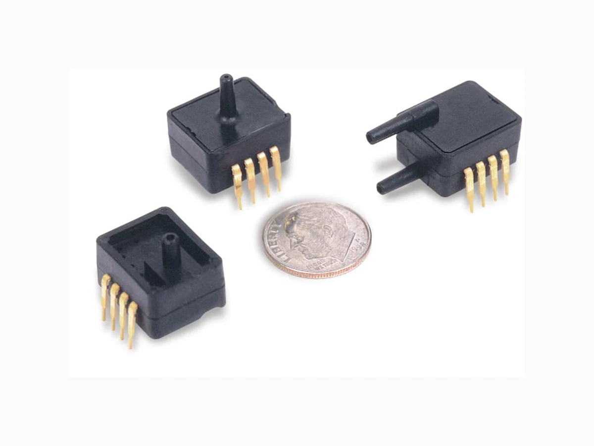
This ASDX series is an amplified version of SenSym ICT’s proven performer and industry leading SDX series sensor. This amplified ASDX device is in a package with the slightly larger footprint as the SDX but it offers a high level (4.0 V span) output on a very cost effective basis. This family is fully calibrated and temperature compensated using an on-board ASIC. These sensors are intended for use with non-corrosive, non-ionic working fluids; such as air and dry gases. Devices are available to measure absolute, differential, and gage pressures from 1 psi (ASDX01DN) through 100 psi (ASDX100). The absolute devices have an internal vacuum reference and an output voltage proportional to absolute pressure. Differential devices allow application of pressure to either side of the sensing diaphragm and can be used for gage or differential measurements. All ASDX devices are accurate to within +/- 2.0%. The devices are characterized for operation from a single 5 volt supply. The sensor is designed and manufactured according to standards laid down in ISO 9001. Contact your local SenSym ICT representative or the factory for additional details.
220nF(7) A/D D/A Microco ntroller +Vs GND C BLOCK DIAGRAM ELECTRICAL CONNECTIONS(8) MAXIMUM RATINGS N/C N/C N/C N/C +Vs Vout GND N/C N/C N/C N/C N/C +Vs Vout GND N/C N/C N/C N/C N/C +Vs Vout GND N/C Vs (PIN 1) IDENTIFIER Vs (PIN 1) IDENTIFIER Vs (PIN 1) IDENTIFIER Pin Out ASDXxxxD4 ASDXxxxG2 ASDXxxxA2 Supply Voltage (Vs)* 4.75V to 5.25Vdc Maximum Supply Voltage* 6.50 Vdc (max.) Consumption Current 6 mA (typ) Output Current - sink 2 mA (max.) Output Current - source 2 mA (max.) Lead Temperature (2-4 Sec.) 250°C *Note: The sensor is not reverse polarity protected. Incorrect application of excitation voltage or ground to the wrong pin can cause electrical failure. Application of supply voltage above the maximum can cause electrical failure. ENVIRONMENTAL SPECIFICATIONS (ALL DEVICES) Temperature Ranges: Compensated: 0°C to + 85°C Vibration: 10G at 20-2000 Hz Operating: -20°C to +105°C Shock: 50G for 11 ms Storage: -40°C to +125°C Life: 1 Million cycles minimum
Note 1: Reference Conditions (unless otherwise noted): Supply voltage, VS=5.0 ± 0.01 Vdc; Ta=25°C. Output is ratiometric within the supply voltage range (Vs). Note 2: Span is the algebraic difference between the output voltage at the specified pressure and the output at zero pressure. Span is ratiometric to the supply voltage. Note 3: Accuracy is the combined errors from offset and span calibration, linearity, pressure hysteresis, and temperature effects. Linearity is the measured deviation based on a straight line. Hysteresis is the maximum output difference at any point within the operating pressure range for increasing and decreasing pressure. Calibration errors include the deviation of offset and full scale from nominal values. Note 4: Response time for a 0 psi to full scale pressure step change, 10% to 90% rise time. Note 5: If maximum burst pressure is exceeded, even momentarily, the package may leak or burst, or the pressure sensing die may fracture. Note 6: The smallest change in the output voltage, given any change in pressure. Note 7: Capacitor 220nF required between +Vs and GND pin. Note 8: Pins 4, 5, 6, 7 and 8 are internal device connections and should not be connected to external circuitry or ground. PRESSURE RANGE SPECIFICATIONS PERFORMANCE CHARACTERISTICS(1) PRESSURE TRANSDUCER PERFORMANCE CHARACTERISTICS 0.5 1.5 Temperature (°C) Temperature Multiplier Error Band Multiplier Over -20°C to +105°C SenSym Pressure Burst Part No. Range Pressure (5) Sensitivity ASDX001 0 – 1 PSI 20 PSI 4.00 V/PSI ASDX005 0 – 5 PSI 20 PSI 0.80 V/PSI ASDX015 0 – 15 PSI 30 PSI 0.267 V/PSI ASDX030 0 – 30 PSI 60 PSI 0.133 V/PSI ASDX100 0 – 100 PSI 150 PSI 0.040 V/PSI Characteristic Symbol Min Typ Max Units Zero Pressure Offset Voff 0.420 0.500 0.580 V Full Scale Span (2) Vfss 4.00 V Output at FS Pressure Vfso 4.420 4.500 4.580 V Accuracy(3) ––– ±2.0 %Vfss Response Time(4) –8 –m s Quantization Step(6) –3 –m V
0 to 1 psi through 0 to 100 psi Pressure Transducers 0.050 typ 0.665 0.310 typ 0.550 0.133 0.143 0.320 0.070 .655±.025 0.325 typ 0.090 typ 0.165 0.350 0.100 typ .050 typ .550 .665 .124 .193 .655±.025 .350 .200 0.105 .177 .100 typ .050 typ 0.333 .665 0.275 .550 .655±.025 .350 .315 0.090 typ .100 typ.177 1 408 954 6700 FAX: 408 954 9458 SenSym ICT
1804 McCarthy Boulevard
Milpitas, CA 95035 www.pressure.invensys.com PHYSICAL DIMENSIONS ORDERING INFORMATION - PART # DESCRIPTION SenSym ICT reserves the right to make changes to any products herein. SenSym ICT does not assume any liability arising out of t he application or use of any product or circuit described herein, neither does it convey any license under its patent rights nor t he rights of others. xxx Device Output: 4R= 0.5 - 4.5Vdc 4D* 4H* 001 = 0 - 1 D, G 4M* 005 = 0 - 5 D, G 015 = 0 - 15 D, G, A Package Style and Type 030 = 0 - 30 D, G, A 100 = 0 - 100 D, G, A A2 = DIP Package, Absolute D4 = DIP Package, Differential *) Contact factory for additional information D2, G2 = DIP Package, Gage 4D* -> 2.5 ± 2Vdc Pressure Range (psi) Pressure Transducer SenSym ICT ASDX XX To order, use the following part number(s) Pressure Range Absolute Gage Differential/Gage 0 – 1 PSI – ASDX001G24R ASDX001D44R 0 – 5 PSI – ASDX005G24R ASDX005D44R 0 – 15 PSI ASDX015A24R ASDX015G24R ASDX015D44R 0 – 30 PSI ASDX030A24R ASDX030G24R ASDX030D44R 0 – 100 PSI ASDX100A24R ASDX100G24R ASDX100D44R For example: Part #ASDX015A24R = ASDX device , 15psi absolute, A2 Package, 0.5 – 4.5V Output