
AS1111C AMSCO
Document overview
- Manufacturer or author: Provided By digicamel.com
- PDF pages: 10
Technical content
DN[Document ID] ams Eval Kit Manual Page 1 [v1-00] 2015-Jan-20 Document Feedback AS1111C Standard Board AS1111C-DF_EK_ST
ams Eval Kit Manual Page 2 [v1-00] 2015-Jan-20 Document Feedback Content Guide
ams Eval Kit Manual Page 3 [v1-00] 2015-Jan-20 Document Feedback
1 Introduction
This document describes the AS1111C Evaluation Kit. The AS1111C is a LED driver designed to match current source bias for any color LED, including white and blue. The device can drive up to 4 high-current LEDs, and the LED current is programmable using an external resistor (RSET). The AS1111C LED currents are 230 x ISET (per LED, type) at an LED cathode voltage (VSAT) of 150mV and 325 x ISET (type) at a VSAT of 1V, where ISET is the current through RSET connected to pin CTRL. The AS1111C incorporate a chip-enable feature via pin EN. When the devices are disabled, the supply current drops down to less than 1µA. The AS1111C is available in a 8lead MLPD package with 0.5mm pitch.
2 Kit Content
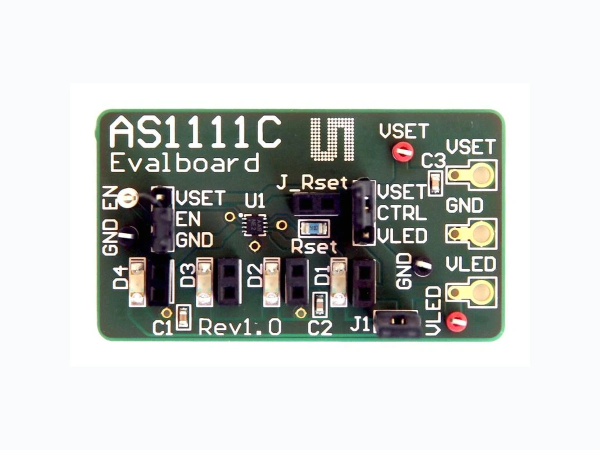
Figure 1: Kit Content Label Item Comment
1 Evaluation Board AS1111C (8lead MLPD 2x2mm package
with 0.5mm pitch)
3 Getting Started
Connect your supply to GND, VSET and VLED. Be shure that the jumpers are set like you can see in the Hardware Description below.
ams Eval Kit Manual Page 4 [v1-00] 2015-Jan-20 Document Feedback
4 Hardware Description
Figure 2: Evaluation Board Overview Label Name Designator Description Info A AS1111C U1 LED – driver B LED´s D1, D2, D3, C VSET VSET Voltage Voltage to set the LED Current D GND GND Ground E VLED VLED LED Supply Supply Voltage for the LED´s Figure 3: Jumper and device locations B C D E A A B C E D
ams Eval Kit Manual Page 5 [v1-00] 2015-Jan-20 Document Feedback Label Name Designator Description Info A J_EN J_EN Enable or Disable the LED – driver GND - disabled VSET - enabled B RSET J_Rset Connect different kind of RSET or you can make a parallel connection. Depending on Jumper J_CTRL. C J_CTRL J_CTRL Connect / Disconnect the soldered (51k) REST resistor. Connect VLED to CTRL CTRL to Vset CTRL to VLED D LED´s J_D1, J_D2; J_D3, J_D4 Female Header Connect different kind of LED´s E J1 J1 Jumper Connect / Disconnect LED´s Figure 4: Measurement Points Label Name Designator Description Info A Enable EN VEN 2.2V: VOUT is enabled VEN 0.5V: VOUT is disabled B GND GND Ground Measurement Point C VSET VSET Voltage to set the LED current Measurement Point D GND GND Ground Measurement Point E LED Voltage VLED Supply Voltage for the LED´s Measurement Point C E D A B
ams Eval Kit Manual Page 6 [v1-00] 2015-Jan-20 Document Feedback
5 Schematics, Layers and BOM
5.1 Schematic of AS1111C Evaluation Board
Figure 5: Schematic D D C C B B A A Size Date Project Title Revision Sheet ofOriginator mkc AS1111C EvalboardA4 1.0 02.08.2013 GNDGND J_EN EN I1 5 I2 6 AS1111 LED DriverEN1 I3 2 CTRL7 GND4 I4 3 EP9 AS1111C GND 0805 Rset 50k Vset J_CTRL CTRL J_Rset Stipline2 Vset J_D1 J_D2 J_D3 J_D4 VLED VLED VLED VLED VLED VSET GND Banana_Socket_THMD VLED1 Vset GND TP_EN Testpoint TP_GND Testpoint 1 TP_VLED Testpoint1 TP_VSET Testpoint TP_GND1 Testpoint LED LED LED LED CTRL EN VLED GND GND 16V 0603 1µF Vset GND 16V 0603 1µF 16V 0603 1µF VLED1 VLED1 VLED1 VLED1 VLED1 VLED1
ams Eval Kit Manual Page 7 [v1-00] 2015-Jan-20 Document Feedback
5.2 Layers
Figure 6: Top Layer Figure 7: Bottom Layer
ams Eval Kit Manual Page 8 [v1-00] 2015-Jan-20 Document Feedback
5.3 Bill of Materials
Figure 8: BOM Bill of Materials AS1111C Evalboard Company: ams AG Originator: mkc PCB Name: AS1111C Evalboard PCB Version: 1.0 Report Date: 02.08.2013 # Designator Comment Component_Description Manufacturer Manufacturer Part Number Quantity
1 C1, C2, C3 1µF CAP CER 1UF 16V 20%
2 D1, D2, D3, D4 LED LED 3.2X1.6MM 630NM RED CLR SMD Kingbright APT3216SURCK 4 J1 3M - 961102-6404-AR - CONNECTOR, HEADER, 2POS, 1ROW, 2.54MM 3M 961102-6404-AR 1 J_CTRL, J_EN CTRL, EN 3M - 961103-6404-AR - BOARD TO BOARD, HEADER, 3POS, 1ROW 3M 961103-6404-AR 2 J_D1, J_D2, J_D3, J_D4, J_RsetD1, D2, D3, D4, [NoValue] SAMTEC - SSA-102-S-G - BUCHSE, 2.54MM, LPT, 2KONT SAMTEC SSA-102-S-G 5 Rset 51k MULTICOMP - MC01W0805151K - WIDERSTAND, 51K, 0.1W, 1%, 0805 MULTICOMP MC01W0805151K 1 TP_EN Testpoint VERO - 20-313139 - PRÜFPUNKT, PCB, WEISS, PK100 VERO 20-313139 1 TP_GND, TP_GND1 Testpoint VERO - 20-2137 - PRÜFPUNKT, PCB, SCHWARZ, PK100 VERO 20-2137 2 TP_VLED, TP_VSET Testpoint VERO - 20-313137 - PRÜFPUNKT, PCB, ROT, PK100 VERO 20-313137 2
10 U1 AS1111C 1
ams Eval Kit Manual Page 9 [v1-00] 2015-Jan-20 Document Feedback
6 Ordering & Contact Information
AS1111C-DF_EK_ST AS1111C Eval Kit Standard Board Buy our products or get free samples online at: www.ams.com/ICdirect Technical Support is available at: www.ams.com/Technical-Support Provide feedback about this document at: www.ams.com/Document-Feedback For further information and requests, e-mail us at: ams_sales@ams.com For sales offices, distributors and representatives, please visit: www.ams.com/contact Headquarters ams AG Tobelbaderstrasse 30
8141 Unterpremstaetten
Austria, Europe Tel: +43 (0) 3136 500 0 Website: www.ams.com
ams Eval Kit Manual Page 10 [v1-00] 2015-Jan-20 Document Feedback
7 Copyrights & Disclaimer
Copyright ams AG, Tobelbader Strasse 30, 8141 Unterpremstaetten, Austria-Europe. Trademarks Registered. All rights reserved. The material herein may not be reproduced, adapted, merged, translated, stored, or used without the prior written consent of the copyright owner. Demo Kits, Evaluation Kits and Reference Designs are provided to r ecipient on an “as is” basis for demonstration and evaluation purposes only and are not considered to be finished end -products intended and fit for general consumer use, commercial applications and applications with special requirements such as but not lim ited to medical equipment or automotive applications. Demo Kits, Evaluation Kits and Reference Designs have not been tested for compliance with electromagnetic compatibility (EMC) standards and directives, unless otherwise specified. Demo Kits, Evaluation Kits and Reference Designs shall be used by qualified personnel only. ams AG reserves the right to change functionality and price of Demo Kits, Evaluation Kits and Reference Designs at any time and without notice. Any express or implied warranties, including, but not limited to the implied warranties of merchantability and fitness for a particular purpose are disclaimed. Any claims and demands and any direct, indirect, incidental, special, exemplary or consequential damages arising from the inadequacy of the provided Demo Kits, Evaluation Kits and Reference Designs or incurred losses of any kind (e.g. loss of use, data or profits or business interruption however caused) as a consequence of their use are excluded. ams AG shall not be liable to recipient or any third party for any damages, including but not limited to personal injury, property damage, loss of profits, loss of use, interruption of business or indirect, special, incidental or consequential damages, of an y kind, in connection with or arising out of the furnishing, performance or use of the technical data herein. No obligation or liability to recipient or any third party shall arise or flow out of ams AG rendering of technical or other services.