


 Download PDF
ARC241 ETC2
Document overview
- PDF pages: 6
Technical content
Page 1

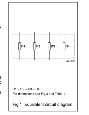
FEATURES
DESCRIPTION
The resistors are constructed on a
- 4 × 0603 sized resistors in one
high grade ceramic body (aluminium
1206-sized package
oxide). Internal metal electrodes are
- Reduced reel exchange time
added at each end and connected by
- Low assembly costs
a resistive paste which is applied to the top surface of the substrate. The
- Reduced PCB area
composition of the paste is adjusted
- Reduced size of final equipment
to give the approximate resistance
- Higher component and equipment
required and the value is trimmed to
reliability.
within tolerance, by laser cutting of this resistive layer.
APPLICATIONS
The resistive layer is covered with a
- Camcorders
protective coating and printed with the
- Hand held measuring equipment
resistance value. Finally, external end terminations are added. For ease of
- Car telephones
soldering the outer layer of these end
- Computers
terminations is a lead-tin alloy.
- Portable radio, CD and cassette players.
QUICK REFERENCE DATA
| DESCRIPTION | VALUE | |||
|---|---|---|---|---|
| ARC241 | ARV241 | ARC242 | ARV242 | |
| Resistance range | 10 Ω to 1 MΩ | |||
| Resistance tolerance and E-series | ±5%; E24 series | ±1%; E96 series | ±1%; E24/E96 series | |
| Temperature coefficient | ≤±200 × 10−6/K | ≤±100 × 10−6/K | ≤±200 × 10−6/K | |
| Absolute maximum dissipation per resistive element at T = 70 °C amb | 0.063 W | |||
| Maximum permissible voltage | 50 V (DC or RMS) | |||
| Climatic category (IEC 60068) | 55/155/56 | |||
| Basic specification | IEC 60115-8 | |||
R-Array overview
| TYPE | TERMINATION TECHNOLOGY | SIZE | TOLERANCE (%) |
|---|---|---|---|
| ARC241 | concave | 4 × 0603 | 5 |
| ARC242 | concave | 4 × 0603 | 1 |
| ARV241 | convex | 4 × 0603 | 5 |
| ARV242 | convex | 4 × 0603 | 1 |
Page 2

FUNCTIONAL DESCRIPTION
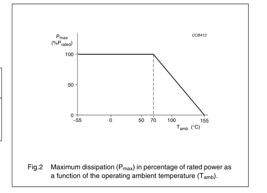
DERATING
The power that the resistor can dissipate depends on the operating ambient
Product characterization
temperature; see Fig.2.
Standard values of nominal resistance are taken from the
E24 or E96 series for resistors with a tolerance of ±5% or ±1%. The values of the E24/E96 series are in accordance with “IEC publication 60063”.
Limiting values
| TYPE | LIMITING VOLTAGE(1) (V) | LIMITING POWER (W) |
|---|---|---|
| ARC241 | 50 | 0.063 |
| ARC242 | ||
| ARV241 | ||
| ARV242 |
Note 1. This is the maximum voltage that may be continuously applied to the resistor element, see “IEC publication 60115-8”.
Page 3

MECHANICAL DATA
PACKAGE MARKING
The packaging is also marked and includes resistance value, tolerance,
Mass per 100 units
catalogue number, quantity, production period, batch number and source code.
| TYPE | MASS (g) |
|---|---|
| ARC241 | 1.1 |
| ARC242 | 1.1 |
| ARV241 | 0.9186 |
| ARV242 | 0.9186 |
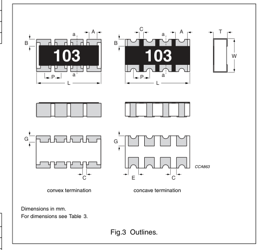
Outlines
Marking
All resistors within the E24 series are marked with a 3-digit code and a 4-digit code for resistors of the E96 series, on the protective coat to designate the nominal resistance value.
3-DIGIT MARKING
For values up to 91 Ω the R is used as a decimal point. For values of 100 Ω or greater the first 2 digits apply to the resistance value and the third indicates the number of zeros to follow.
Example
| MARKING | RESISTANCE |
| 12R | 12 Ω |
| 124 | 120 kΩ |
| 000 | jumper |
Table 3 Physical dimensions; see Fig.3
| SYMBOL | ARC241/242 | ARV241 | ARV242 | UNIT | |||
|---|---|---|---|---|---|---|---|
| VALUE | TOL. | VALUE | TOL. | VALUE | TOL. | ||
| L | 3.20 | +0.20/−0.10 | 3.20 | ±0.15 | 3.20 | ±0.15 | mm |
| W | 1.60 | +0.20/−0.10 | 1.60 | ±0.15 | 1.60 | ±0.15 | mm |
| T | 0.60 | ±0.20 | 0.55 | ±0.10 | 0.55 | ±0.10 | mm |
| A | 0.60 | ±0.15 | 0.40 | ±0.15 | 0.60 | ±0.05 | mm |
| B | 0.35 | ±0.15 | 0.30 | ±0.20 | 0.30 | ±0.20 | mm |
| P | 0.80 | ±0.15 | 0.80 | ±0.15 | 0.80 | ±0.15 | mm |
| E | 0.50 | ±0.15 | − | − | − | − | mm |
| G | 0.50 | ±0.15 | 0.30 | ±0.15 | 0.30 | ±0.15 | mm |
| C | 0.10 | min. | 0.10 | min. | 0.40 | ±0.15 | mm |
4-DIGIT MARKING
For values up to 976 Ω the R is used as a decimal point. For values of 1 K or greater the first 3 digits apply to the resistance value and the fourth indicates the number of zeros to follow.
Example
| MARKING | RESISTANCE |
| 12R0 | 12 Ω |
| 1203 | 120 kΩ |
Page 4
TESTS AND REQUIREMENTS
Essentially all tests are carried out in accordance with the schedule of “IEC publication 60115-8”, category LCT/UCT/56 (rated temperature range: Lower Category Temperature, Upper Category Temperature; damp heat, long term, 56 days). The testing also covers the requirements specified by EIA and EIAJ.
The tests are carried out in accordance with IEC publication 60068, “Recommended basic climatic and mechanical robustness testing procedure for electronic components” and under standard atmospheric conditions according to “IEC 60068-1”, subclause 5.3.
Table 4 Test procedures and requirements
Unless otherwise specified the following values apply: Temperature: 15 °C to 35 °C Relative humidity: 25% to 75% Air pressure: 86 kPa to 106 kPa (860 mbar to 1060 mbar).
In Table 4 the tests and requirements are listed with reference to the relevant clauses of “IEC publications 60115-8 and 60068”; a short description of the test procedure is also given. In some instances deviations from the IEC recommendations were necessary for our method of specifying.
All soldering tests are performed with mildly activated flux.
| IEC 60115-8 CLAUSE | IEC 60068-2 TEST METHOD | TEST | PROCEDURE | REQUIREMENTS | |||
| ARC241 | ARV241 | ARC242 | ARV242 | ||||
| Tests in accordance with the schedule of IEC publication 60115-8 | |||||||
| 4.4.1 | visual examination | no holes; clean surface; no visible damage | |||||
| 4.4.2 | dimensions (outline; see Fig.3) | gauge (mm) | see Table 3 | − | |||
| 4.5 | resistance | applied voltage (+0/−10%): 10 Ω≤R < 100 Ω: 0.3 V 100 Ω≤R < 1 kΩ: 1 V 1 kΩ≤R < 10 kΩ: 3 V 10 kΩ≤R < 100 kΩ: 10 V 100 kΩ≤R < 1 MΩ: 25 V R ≥1 MΩ: 50 V | R −R : nom max. ±5% | R −R : nom max. ±1% | R −R : nom max. ±5% | ||
| 4.18 | 20 (Tb) | resistance to soldering heat | unmounted chips; 10 ±1 s; 260 ±5 °C | no visible damage | |||
| ∆R/R max.: ±(0.5% +0.05 Ω) | ∆R/R max.: ±(1% +0.05 Ω) | ||||||
| 4.29 | 45 (Xa) | component solvent resistance | isopropyl alcohol or H O followed by 2 brushing in accordance with “MIL 202 F” | no visible damage | |||
| 4.17 | 20 (Ta) | solderability | unmounted chips completely immersed for 2 ±0.5 s in a solder bath at 235 ±2 °C | good tinning (≥95% covered); no visible damage | |||
Page 5
| IEC 60115-8 CLAUSE | IEC 60068-2 TEST METHOD | TEST | PROCEDURE | REQUIREMENTS | |||
| ARC241 | ARV241 | ARC242 | ARV242 | ||||
| 4.7 | voltage proof on insulation | maximum voltage (RMS) during 1 minute, metal block method | no breakdown or flashover | ||||
| 4.13 | short time overload | room temperature; P = 6.25 × P ; n 5 s (V ≤2 × V ) max | ∆R/R max.: ±(1% +0.05 Ω) | ∆R/R max.: ±(2% +0.1 Ω) | |||
| 4.33 | bending | resistors mounted on a 90 mm glass epoxy resin PCB (FR4), bending: 5 mm | no visible damage | ||||
| ∆R/R max.: ±(1% +0.05 Ω) | ∆R/R max.: ±(0.5% +0.05 Ω) | ∆R/R max.: ±(1% +0.05 Ω) | |||||
| 4.19 | 14 (Na) | rapid change of temperature | 30 minutes at LCT and 30 minutes at UCT; 5 cycles | no visible damage | |||
| ∆R/R max.: ±(0.5% +0.05 Ω) | ∆R/R max.: ±(1% +0.05 Ω) | ||||||
| 4.24.2 | 3 (Ca) | damp heat (steady state) | 56 days; 40 ±2 °C; 93 +2/−3% RH; loaded with 0.01 P n | ∆R/R max.: ±(3% +0.1 Ω) | ∆R/R max.: ±(1% +0.05 Ω) | ∆R/R max.: ±(2% +0.1 Ω) | |
| 4.25.1 | endurance | 1000 +48/−0 hours; 70 ±2 °C; loaded with P or V ; 1.5 hours on and 0.5 hours off n max | ∆R/R max.: ±(2% +0.1 Ω) | ∆R/R max.: ±(1% +0.05 Ω) | ∆R/R max.: ±(2% +0.1 Ω) | ||
| 4.23.2 | 27 (Ba) | endurance at upper category temperature | 1000 +48/−0 hours; no load | ∆R/R max.: ±(2% +0.1 Ω) | ∆R/R max.: ±(1% +0.05 Ω) | ∆R/R max.: ±(2% +0.1 Ω) | |
| 4.8.4.2 | temperature coefficient | at 20/LCT/20 °C and 20/UCT/20 °C | ≤±200 × 10−6/K | ≤±100 × 10−6/K | ≤±200 × 10−6/K | ||
| Other tests in accordance with IEC 60115 clauses and IEC 60068 test method | |||||||
| 4.17 | 20 (Ta) | solderability (after ageing) | 8 hours steam or 16 hours 155 °C; unmounted chips completely immersed for 2 ±0.5 s in a solder bath at 235 ±2 °C | good tinning (≥95% covered); no damage | |||
| 4.6.1.1 | insulation resistance | voltage (DC) after 1 minute, metal block method: 10 V | R min.: 103 MΩ ins | ||||
| 4.12 | noise | IEC publication 60195 (measured with Quantech-equipment): R ≤100 Ω 100 Ω< R ≤1 kΩ 1 kΩ< R ≤10 kΩ 10 kΩ< R ≤100 kΩ 100 kΩ< R ≤1 MΩ | max. 0.316 µV/V (−10 dB) max. 1 µV/V (0 dB) max. 3 µV/V (9.54 dB) max. 6 µV/V (15.56 dB) max. 10 µV/V (20 dB) | ||||
Page 6
| IEC 60115-8 CLAUSE | IEC 60068-2 TEST METHOD | TEST | PROCEDURE | REQUIREMENTS | |||
| ARC241 | ARV241 | ARC242 | ARV242 | ||||
| Other applicable tests | |||||||
| (JIS) C 5202 7.9 | endurance (under damp and load) | 1000 +48/−0 hours; 40 ±2 °C; 93 +2/−3% RH; loaded with P or V ; n max 1.5 hours on and 0.5 hours off | ∆R/R max.: ±(3% +0.1 Ω) | ∆R/R max.: ±(2% +0.1 Ω) | |||
| EIA 575 3.13 | leaching | unmounted chips; 60 ±1 s; 260 ±5 °C | good tinning; no leaching | ||||
| EIA/IS 703 4.5 | load humidity | 1 000 +48/−0 hours; 85 ±2 °C; 85 ±5% RH; loaded with 0.01 P or V n max | ∆R/R max.: ±(2% +0.1 Ω) | ||||