

 Download PDF
AR49-M49M ABRACON
Document overview
- PDF pages: 18
Technical content
Page 1
Data Sheet
AR49-M49M/M25S Series
Absolute Reflective Encoder Module with Energy-Harvesting Multi-Turn Counter
Description
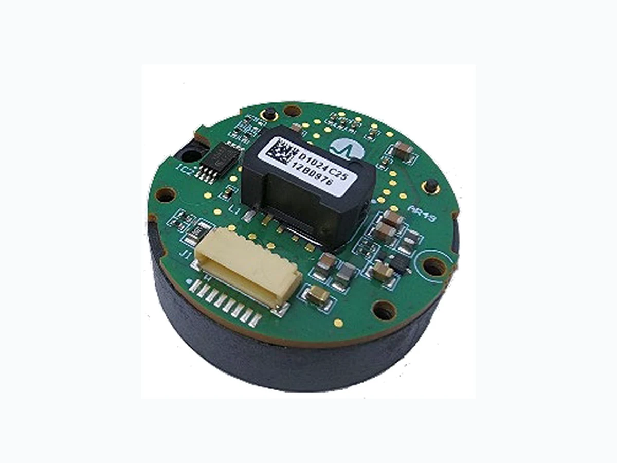
The Broadcom® AR49 series is an optical absolute encoder module that offers up to 25-bit single-turn (ST) position
information and 24-bit multi-turn (MT) counts, hence a
combined 49-bit high-resolution output. The ST block of the
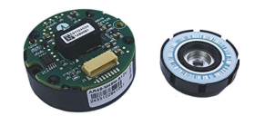
encoder consists of a patterned disk, a light source, and photosensitive elements to translate the mechanical motion
into an electrical signal. The encoder is designed with a selection of serial communication protocols, with a
dedicated electronic circuit designed for robust signal communication.
Broadcom AR49 series encoders offer many intelligent
features, such as Built-In Temperature Sensor, User Programmable Resolution, Zero Reset, System Alarm, and more. They come with a recommended high-temperature
range of –40°C to 115°C. One of the key advantages is their multi-turn tracking, which employs a proprietary energyharvesting (EH) technology by harvesting the magnetic
energy while the patterned disk with magnet rotates. The
counter ASIC harvests the energy generated by the EH
sensor for processing the rotational count and generates
counting logic to non-volatile memory, which updates and stores the count.
The entire operation of energy generation, counting, and storage processing is completed with limited energy and a short duration; hence, the kit encoder is suited for both lowspeed and high-speed measurement.
Features and Benefits
24-bit energy-harvesting multi-turn and 25-bit optical single-turn Accuracy upon calibration of ±30 arc-seconds Encoder fault and status bits with CRC Integrated differential transceiver for the SSI/BiSS-C/ RS485 communication protocols Single-ended Serial Protocol Interface (SPI 4-wire option) Overall encoder outer diameter of Ø35 mm and maximum height of 17.5 mm 8K bits of user-accessible memory in EEPROM Immediate position detection on power-up; no battery or capacitor required for position detection during a power failure RoHS compliant
Applications
AC/DC servo motor feedback Medical and laboratory equipment Robotics Factory automation
NOTE:
The AR49 series encoders are not halogen-free products.
CAUTION! This product is not specifically designed or
manufactured for use in any specific devices. Customers are solely responsible for determining the suitability of the product for its intended application and solely liable for all loss, damage, expense, or liability in connection with such use. Contact Broadcom for further inquiry.
December 4, 2024
Page 2
Product Specifications
Table 1: Absolute Maximum Ratingsa
| Parameters | Symbol | Min. | Max. | Units | Notes |
|---|---|---|---|---|---|
| Storage Temperature | T S | –40 | 125 | °C | — |
| Operating Temperatureb | T a | –40 | 115 | °C | — |
| Supply Voltage | V DD | –0.3 | 6.5 | V | — |
| Electrostatic Discharge Immunity, ESD | — | –8k | +8k | V | Contact discharge |
| — | –12k | +12k | V | Air discharge | |
| Electrical Fast Transient/Burst Immunity, EFT | — | –2k | +2k | V | 5 minutes, 5 kHz |
| Permissible Speedc | — | — | 12,000 | RPM | — |
| Relative Humidity | RH | — | 90 | % | T = 60°C (non-condensing) |
| Single-Turn Resolution | — | 15 | 25 | bit | 15 to 25 bits |
| Multi-Turn Resolution | — | 0 | 24 | bit | 12, 14, 16, 18, 20, 22, and 24 bits |
| Transmission Lengthd | — | — | 25 | meter | SSI/BiSS-C/RS485 differential line |
a. Exposure to absolute maximum rating conditions for extended periods can affect reliability. Stress greater than the absolute maximum rating can cause permanent damage to the device. b. The maximum junction temperature of the PCB shall not exceed 125°C. c. The encoder works reliably up until this permissible speed. d. A twisted-pair shielded cable is recommended for robustness against environmental noise. Frame ground (FG) termination near the motor frame is recommended.
Table 2: Electrical Characteristics
DC characteristics over the recommended operating conditions of VDD 4.5V to 5.5V, Ta = –40°C to 115°C.
| Parameters | Symbol | Min. | Typ. | Max. | Unit | Notes |
|---|---|---|---|---|---|---|
| Supply Voltage | V DD | 4.5 | 5.0 | 5.5 | V | — |
| Supply Current | I DD | 50 | 60 | 100 | mA | BiSS/SSI/SPI4 options |
| 68 | RS485 option (with oscillator) | |||||
| Power on Standby | — | — | — | 500 | ms | — |
| Protocol I/O Drive Strength | I DIO | 5 | 20 | 40 | mA | Differential driver |
| Electrically Permissible Speed | — | –12,000 | — | +12,000 | RPM | — |
| Differential Transceiver | ||||||
| Hysteresis Voltage | V hys | — | 100 | — | mV | 220Ω termination |
| Opening Voltage | V open | 200 | — | — | mV | — |
| Peak-Peak Voltage | V PP | — | 2 | — | V | — |
| I/O Line (SPI Single-Ended) | ||||||
| Output High Voltage | V OH | 4.4 | — | — | V | No load (V = 5V) DD |
| Output Low Voltage | V OL | — | — | 0.5 | V | — |
| Input High Voltage | V IH | 2.8 | — | 5.5 | V | — |
| Input Low Voltage | V IL | 0 | — | 1.8 | V | — |
Page 3
Table 3: Mechanical and Environmental Specifications
Mechanical characteristics over the recommended operating conditions of VDD 4.5V to 5.5V, Ta = –40°C to 115°C.
| Parameters | Conditions | Min. | Typ. | Max. | Units |
|---|---|---|---|---|---|
| Storage Temperature | — | –40 | — | 125 | °C |
| Operating Temperaturea | — | –40 | — | 115 | °C |
| Encoder Accuracyb | With reference encoder correction, T = 25°C a | — | ±30 | — | Arc-sec |
| Mechanical Permissible Speed | — | –12,000 | — | +12,000 | RPM |
| Relative Air Humidity (Non-Condensing) | T = 60°C a | — | 90 | — | RH% |
| Vibration | EN 60068-2-6 | — | — | 30 | G |
| Shock | EN 60068-2-27, 6 ms | — | — | 100 | G |
a. Maximum junction temperature of the PCB shall not exceed 125°C. b. Typical values represent the accuracy and repeatability when calibrated with a reference encoder having 10× higher accuracy than the AR49. Reference encoder ≈ 3 arc-seconds.
CAUTION! Refrain from placing the code-wheel magnet or any magnet near the EH sensor on top of the encoder assembly
(maintain a storage condition <20 mT).
Table 4: General Encoder Specifications
| Parameters | Notes |
|---|---|
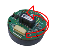
| Default Counting Direction | Increases with counter-clockwise (CCW) code-wheel rotation; view from encoder top (Figure 1) |
| User-Accessible Memory Size | 8K bits |
| Encoder Temperature | 8-bit data output at 1°C resolution |
| Initialization Time | 500 ms |
Figure 1: Counting Up Direction from Top View
Top View
Page 4
Mechanical Specifications
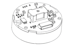
Package Dimensions – AR49-M49M Series MT Option
Figure 2: MT Encoder Mechanical Dimensions
Horizontal Connector
Vertical Connector
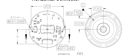
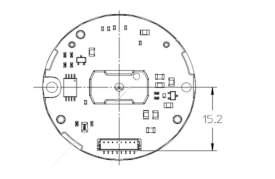
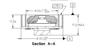
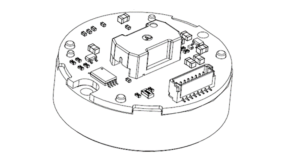
Code-Wheel Assembly
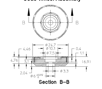
NOTE:
Dimensions are in millimeters. Third angle projection. Motor-shaft outer diameter requirement: 6g6 (–0.004, –0.012) mm.
Page 5
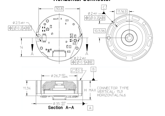
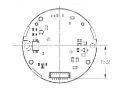
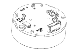
Package Dimensions – AR49-M25S Series ST Option
Figure 3: ST Encoder Mechanical Dimensions
Vertical Connector
Horizontal Connector
Code-Wheel Assembly
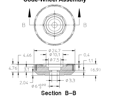
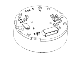
NOTE:
Dimensions are in millimeters. Third angle projection. Motor-shaft outer diameter requirement: 6g6 (–0.004, –0.012) mm.
Page 6
Recommended Motor Mounting Dimensions
Figure 4: Mounting Dimensions When Using the Module Outer Diameter (OD) as the Position Guide
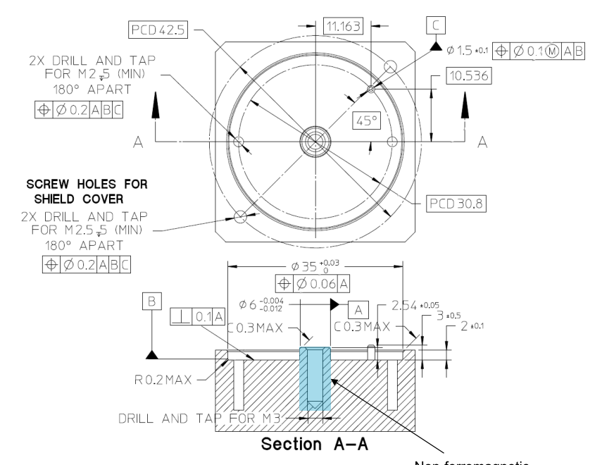
Non-ferromagnetic
material
NOTE:
Dimensions are in millimeters. Third angle projection. Use a stainless steel M3 screw to secure the code-wheel–hub assembly to the motor shaft. Use a screw with pre-applied thread locker. The motor-shaft end where the code wheel is mounted must be made of non-ferromagnetic material. Recommended motor-shaft material: SUS316L.
Page 7
Figure 5: Mounting Dimensions When Using the Module Inner Diameter (ID) as the Position Guide
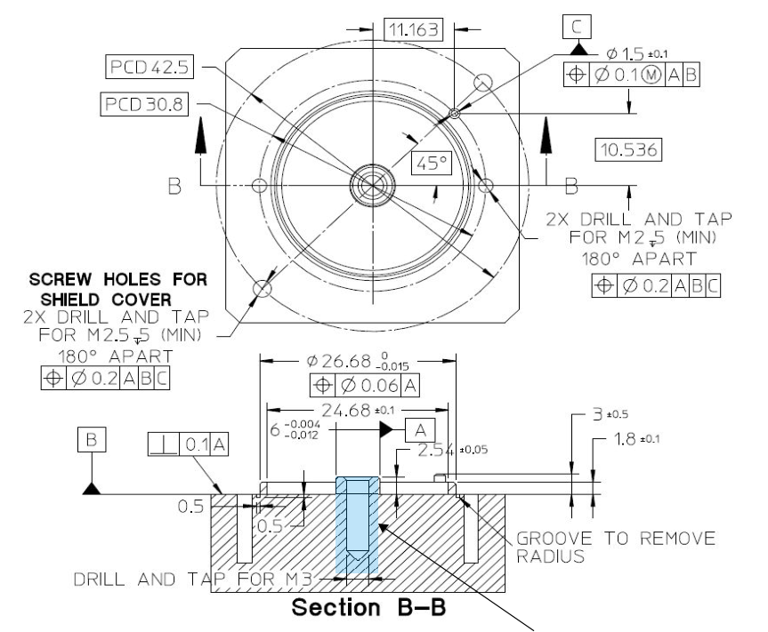
Non-ferromagnetic
Material
NOTE:
Dimensions are in millimeters. Third angle projection. Use a stainless steel M3 screw to secure the code-wheel–hub assembly to the motor shaft. Use a screw with pre-applied thread locker. The motor-shaft end where the code wheel is mounted must be made of non-ferromagnetic material. Recommended motor-shaft material: SUS316L.
Page 8
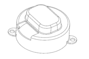
Recommended Shield Cover Dimensions
To eliminate or minimize the influence of the external magnetic field interference on encoder operation, use of shielding is
mandatory.
Shield cover material requirement: Mild steel SPCC-SD, thickness 0.8 mm (minimum). Finishing: Ni plating 8 μm to 12 μm thick, with Cu undercoating 2 μm to 4 μm.
Figure 6: Reference Shield Cover Design
Encoder Calibration
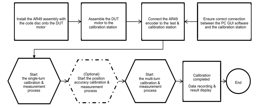
Broadcom encoders employ an intelligent calibration method by performing auto signal optimization once the encoder is
mounted within assembly tolerances. This eliminates the hassle of mechanically adjusting the encoder position to a very
tight gap and mechanical center. Position accuracy correction is optional and can be carried out with a high-accuracy reference encoder, for example Broadcom’s AR25-AC25 calibration station.
For initial development and early evaluation of the AR49 encoders, the versatile AR49-M49-E01 programming kit can be used to perform the basic encoder configuration and calibration process.
Figure 7: Overview of the AR49 Series Encoder Calibration Flow
Page 9
Interface Protocol
AR49-M49M/M25S-Kxx with RS485 Half-Duplex Protocol
A one-to-one half-duplex serial communication is established between the client encoder and the host (for example, a servo driver). The communication is in a differential transmission format. The encoder will perform specific operations based on the command requests made by the host. Before the encoder executes the requested operation, an acknowledgment of the command request is necessary after first checking the start bit, information data field, and stop bit. If this check fails, the encoder will not acknowledge and execute the received command request.
Figure 8: General Transmission Frames Format on Half-Duplex Line
Data Frames

Transmission Frames Set
Transmission Frame (Host Request)
(Client Encoder Response)
Host Request Frames Set Host
NOTE:
Start of transmission frames set: Upon detecting the first logic of Low State "0" on the transmission line after an idle state, and if the following three bits conform to the sync code, the encoder will acknowledge it as a valid Request Control Field (RCF), which indicates the start of a transmission frame set. Otherwise, the encoder will continue to search for the next available logic of Low State "0". End of transmission frames set: After the command frame is detected, if there is no start bit after the end bit of the last frame read, and no subsequent frame is detected, the end of transmission frames set is concluded. Idle state: The idle state means a space between each transmission frames set and subsequent transmission
frames. At the idle state, the logic of the output in the transmission line is kept to high state "1".
Table 5: RS485 Protocol Specifications
Over the recommended operating conditions of VDD 4.5V to 5.5V, Ta = –40°C to 115°C.
| Parameters | Conditions | Min. | Typ. | Max. | Unit | Notes |
|---|---|---|---|---|---|---|
| Communication Baud Rate | — | — | 2.5 | 10 | Mb/s | 2.5, 5, 10 Mb/s |
| Frame Length | — | — | 10 | — | Bit/Frame | — |
| Cycle Time Between Frames Set Request | Command ID3 | 62.5 | — | — | μs | 2.5 Mb/s |
| 35 | — | — | — | 5 Mb/s | ||
| 20 | — | — | — | 10 Mb/s | ||
| Jitter | Every Frame | –100 | — | 100 | ns | 2.5 Mb/s |
| –50 | — | 50 | ns | 5 Mb/s | ||
| –25 | — | 25 | ns | 10 Mb/s |
Page 10
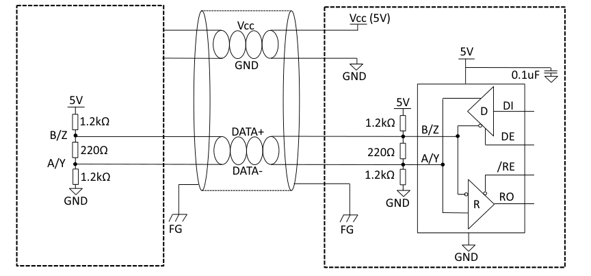
RS485 Differential Connection
The recommended I/O connection between the encoder and the host driver has the following basic requirements:
- Ensure that the encoder power supply, VCC, is within the range of 4.5V to 5.5V. 2. For best noise immunity, use a twisted-pair shielded cable for connection to the servo driver.
- To prevent undesirable signal reflection, terminate with 220Ω resistors.
- Terminate the shield-wire to frame ground (FG) at both ends of the communication line.
Figure 9: RS485 Half-Duplex I/O Connection
Encoder
Controller
Page 11
AR49-M49M/M25S-Bxx with BiSS-C Serial Interface
Table 6: BiSS-C Timing Characteristics
Over the recommended operating conditions of VDD 4.5V to 5.5V, Ta = –40°C to 115°C.
| Parameters | Symbol | Condition | Min. | Typ. | Max. | Units |
|---|---|---|---|---|---|---|
| MA Frequency | f MA | — | 0.08 | — | 10 | MHz |
| MA Duty | DUT CLK | — | — | 50 | — | % |
| Busy Time | T busy | f = 5 MHz to 10 MHz MA | — | 2/f MA | — | μs |
| 100 kHz ≤ f < 5 MHz MA | — | 1/f MA | — | |||
| Timeout | t BiSS-timeout | — | 1.5/f MA | — | 5 | μs |
| Frame to Frame | — | — | — | — | 1 | μs |
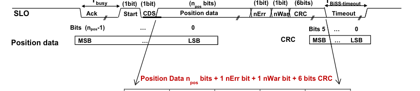
Figure 10: BiSS-C Data Field and Interface Timing Diagram
T
MA
CDM(invert)
Tbusy
TBiSS-timeout
MT[23:0]
ST[24:0]
Error[0]
Warning[0] CRC[5:0]
NOTE:
CRC polynomial = Invert of (X6 + X1 + X0). The nErr bit is active low. (Combines all the Error Status and reflects in the nErr bit). The nWar bit is active low. (Combines all the Warning Status and reflects in the nWar bit). The position data varies depending on the single-turn and multi-turn resolution.
The recommended I/O connection between the encoder and the host driver has the following basic requirements.
Page 12
BiSS-C Full-Duplex Connection
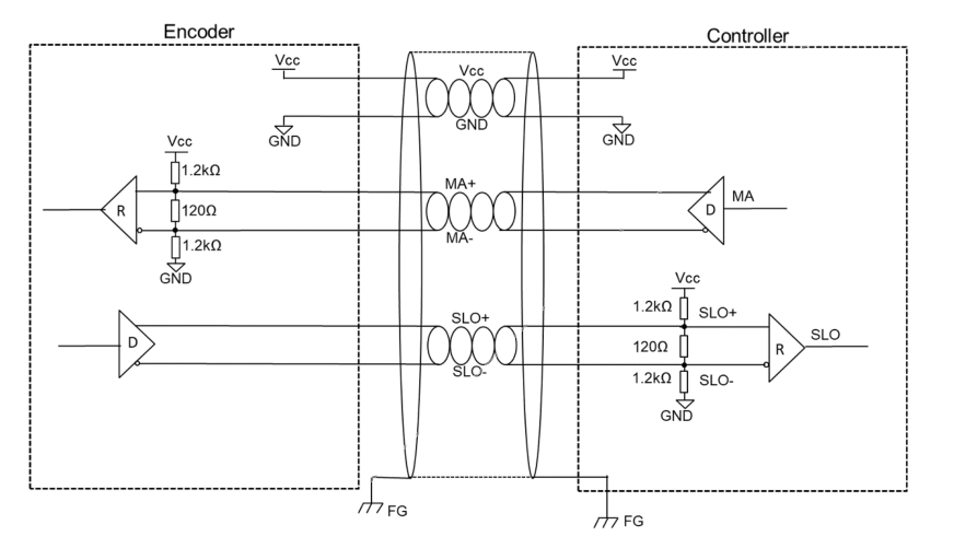
- Provide the following encoder power supply: – For the 5.0V supply, VCC should be within the range of 4.5V to 5.5V. 2. For best noise immunity, use a twisted-pair shielded cable for connection to the servo driver.
- To prevent undesirable signal reflection, terminate with 120Ω resistors.
- Terminate the shield-wire to frame ground (FG) at both ends of the communication line.
Figure 11: BiSS-C Full-Duplex I/O Connection
Page 13
AR49-M49M/M25S-Sxx with SSI 2-Wire Serial Interface
Table 7: SSI Protocol Specifications
Over the recommended operating conditions of VDD 4.5V to 5.5V, Ta = –40°C to 115°C.
| SSI Communication Parameters | Symbol | Conditions | Min. | Typ. | Max. | Unit |
|---|---|---|---|---|---|---|
| Clock Frequency | f CLK | — | 100 | — | 10,000 | kHz |
| Clock Duty | DUT CLK | — | — | 50 | — | % |
| Monoflop Time | t m | — | — | — | 20 | μs |
| Pause Time | t p | — | 21 | — | — | μs |
Figure 12: SSI Data Field and Timing Diagram

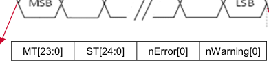
24 bits
25 bits
1 bit
1 bit
For the SSI option, the encoder calibration and device configuration are achieved by switching to the SPI mode during calibration. By toggling the logic levels of the SEL0 and SEL1 pins, the SPI calibration mode can be enabled.
Page 14
SSI 2-Wire Full-Duplex Connection
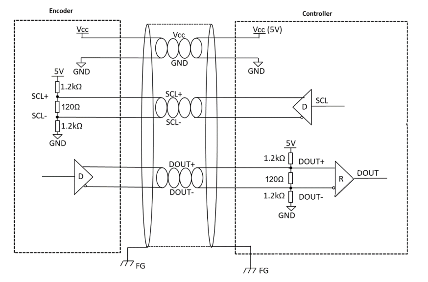
- Provide the following encoder power supply: – For the 5.0V supply, VCC should be within the range of 4.5V to 5.5V. 2. For best noise immunity, use a twisted-pair shielded cable for connection to the servo driver.
- To prevent undesirable signal reflection, terminate with 120Ω resistor.
- Terminate the shield-wire to frame ground (FG) at both ends of the communication line.
Figure 13: SSI Full-Duplex Connection
Page 15
AR49-M49M/M25S-Pxx with SPI 4-Wire Protocol
Figure 14: SPI Timing Diagram
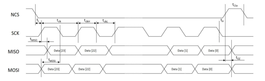
Table 8: SPI Protocol Specifications
Over the recommended operating conditions of VDD 4.5V to 5.5V, Ta = –40°C to 115°C.
| Symbol | Description | Min. | Typ. | Max. | Units |
|---|---|---|---|---|---|
| tL | Time between the NCS falling edge and the CLK rising edge | 350 | — | — | ns |
| tclk | Serial clock period | 100 | — | — | ns |
| tclkL | Low period of the serial clock | 50 | — | — | ns |
| tclkH | High period of the serial clock | 50 | — | — | ns |
| tH | Time between the last falling edge of SCK and the rising edge of NCS | tclk/2 | — | — | ns |
| t NCS | High time of NCS between two transmissions | 350 | — | — | ns |
| tMOSI | Data input valid to the clock edge | 20 | — | — | ns |
| tMISO | SCK edge to the data output valid | — | 51 | — | ns |
| tOZ | Time between the NCS rising edge and the MISO Hi-Z | — | 10 | — | ns |
NOTE: The user should read back data to confirm that data has been written successfully.
Page 16
Connector Information
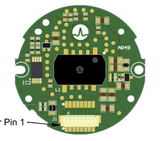
Figure 15: Horizontal and Vertical Connector Information
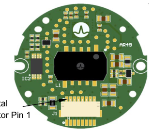
Horizontal
Vertical
Connector Pin 1
Connector Pin 1
Table 9: Recommended Connector Information
| Part | Location | Manufacturer | Part Number | Description |
|---|---|---|---|---|
| Header | On PCB | JST | SM08B-SRSS-TB | Horizontal/radial connector |
| JST | BM08B-SRSS-TB | Vertical/axial connector | ||
| Wire Plug | Mating plug for wires | JST | SHR-08V-S | — |
| Crimp Pins | Crimp pins for wires | JST | SSH-003T-P0.2-H | Terminal pin for wire 32~28 AWG |
Table 10: Encoder Pinout Description
| Pin # | BiSS-C | SPI | SSI a, b | RS485 |
| 1 | +5V | +5V | +5V | +5V |
| 2 | 0V | 0V | 0V | 0V |
| 3 | MA+ | SPI-NCS | SCLK+/SPI-NCS | NC |
| 4 | MA- | SPI-CLK | SCLK-/SPI-CLK | NC |
| 5 | SLO+ | SPI-DO/MISO | DATA+/SPI-DO/MISO | DATA+ |
| 6 | SLO- | SPI-DIN/MOSI | DATA-/SPI-DIN/MOSI | DATA- |
| 7 | NC | NC | SEL0 | NC |
| 8 | NC | NC | SEL1 | NC |
a. The SSI option is configured via the shared SPI pins and setting the correct logic level for the SEL0 and SEL1 pins. b. For the SSI option, when switching to communicate with the SPI protocol, Pin 3 and Pin 4 of the SPI-NCS and SPI-CLK lines require a strong driver current due to the SSI SCLK+/SCLK- terminating resistor. It is recommended to be achieved with a level shifter or a line driver circuit.
Page 17
Part Numbering
Figure 16: AR49 Module Encoder Part Number Definition
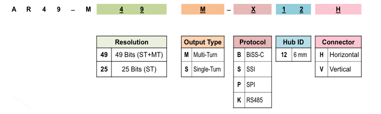
Table 11: Encoder Ordering Information
| No. | Multi-Turn Part Number | Description |
|---|---|---|
| 1 | AR49-M49M-S12V | 49-Bit MT, Differential SSI, 6-mm Shaft, M3 Mounting Screw, Vertical Connector. |
| 2 | AR49-M49M-P12V | 49-Bit MT, Single-Ended SPI 4-Wire, 6-mm Shaft, M3 Mounting Screw, Vertical Connector. |
| 3 | AR49-M49M-K12V | 49-Bit MT, Differential RS485, 6-mm Shaft, M3 Mounting Screw, Vertical Connector. |
| 4 | AR49-M49M-B12V | 49-Bit MT, Differential BiSS-C, 6-mm Shaft, M3 Mounting Screw, Vertical Connector. |
| 5 | AR49-M49M-S12H | 49-Bit MT, Differential SSI, 6-mm Shaft, M3 Mounting Screw, Horizontal Connector. |
| 6 | AR49-M49M-P12H | 49-Bit MT, Single-Ended SPI 4-Wire, 6-mm Shaft, M3 Mounting Screw, Horizontal Connector. |
| 7 | AR49-M49M-K12H | 49-Bit MT, Differential RS485, 6-mm Shaft, M3 Mounting Screw, Horizontal Connector. |
| 8 | AR49-M49M-B12H | 49-Bit MT, Differential BiSS-C, 6-mm Shaft, M3 Mounting Screw, Horizontal Connector. |
| No. | Single-Turn Part Number | Description |
| 9 | AR49-M25S-S12V | 25-Bit ST, Differential SSI, 6-mm Shaft, M3 Mounting Screw, Vertical Connector. |
| 10 | AR49-M25S-P12V | 25-Bit ST, Single-Ended SPI 4-Wire, 6-mm Shaft, M3 Mounting Screw, Vertical Connector. |
| 11 | AR49-M25S-K12V | 25-Bit ST, Differential RS485, 6-mm Shaft, M3 Mounting Screw, Vertical Connector. |
| 12 | AR49-M25S-B12V | 25-Bit ST, Differential BiSS-C, 6-mm Shaft, M3 Mounting Screw, Vertical Connector. |
| 13 | AR49-M25S-S12H | 25-Bit ST, Differential SSI, 6-mm Shaft, M3 Mounting Screw, Horizontal Connector. |
| 14 | AR49-M25S-P12H | 25-Bit ST, Single-Ended SPI 4-Wire, 6-mm Shaft, M3 Mounting Screw, Horizontal Connector. |
| 15 | AR49-M25S-K12H | 25-Bit ST, Differential RS485, 6-mm Shaft, M3 Mounting Screw, Horizontal Connector. |
| 16 | AR49-M25S-B12H | 25-Bit ST, Differential BiSS-C, 6-mm Shaft, M3 Mounting Screw, Horizontal Connector. |
Table 12: Accessories Ordering Information
| No. | Part Number | Description |
|---|---|---|
| 1 | AS20-C300 | 8-pin mating connector with 300-mm cable length. |
| 2 | AR49-M49-E01 | Programming Kit (applicable for all protocol options). Contents: 1 unit of MCU-based programming kit, 1 unit of USB cable for the PC interface, the DUT cable, and the associated programming software. |
| 3 | AR25-AC25 | Accuracy Calibration Station for the AR25/AR49 Series Rotary Reflective Encoder. Contents: Mechanical setup including the servo motor control, high-accuracy reference encoder, programming kits, associated cable assemblies (for the PC interface, motor handler communication, DUT encoder connection), and the associated GUI programming software. |
Page 18
Copyright © 2024 Broadcom. All Rights Reserved. The term “Broadcom” refers to Broadcom Inc. and/or its subsidiaries. For more information, go to www.broadcom.com. All trademarks, trade names, service marks, and logos referenced herein belong to their respective companies.
Broadcom reserves the right to make changes without further notice to any products or data herein to improve reliability, function, or design. Information furnished by Broadcom is believed to be accurate and reliable. However, Broadcom does not assume any liability arising out of the application or use of this information, nor the application or use of any product or circuit described herein, neither does it convey any license under its patent rights nor the rights of others.