
DATASHEET SEARCH SITE
Document overview
- Manufacturer or author: Provided By digicamel.com
- PDF pages: 4
Technical content
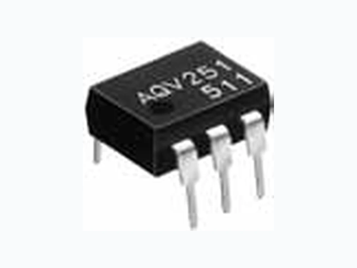
Panasonic Corporation Automation Controls Business Unit industrial.panasonic.com/ac/e HE 1 Form A (AQV25❍) ASCTB143E 201201-T TYPES *Indicate the peak AC and DC values. Note: The surface mount terminal indicator “A” and the packing style indicator “X” or “Z” are not marked on the device. RATING Both low on-resistance and good cost-performance achieved. HE 1 Form A (AQV25❍) I/O isolation Output rating* Package Part No. Packing quantityThrough hole terminal Surface-mount terminal Load voltage Load current Tube packing style Tape and reel packing style Tube Tape and reelPicked from the 1/2/3-pin side Picked from the 4/5/6-pin side AC/DC dual use 1,500V
40 V 500 mA
AQV251 AQV251A AQV251AX AQV251AZ 1 tube contains: 50 pcs. 1 batch contains: 500 pcs. 1,000 pcs.
60 V 400 mA AQV252 AQV252A AQV252AX AQV252AZ
100 V 350 mA AQV255 AQV255A AQV255AX AQV255AZ
200 V 250 mA AQV257 AQV257A AQV257AX AQV257AZ
250 V 200 mA AQV253 AQV253A AQV253AX AQV253AZ
400 V 150 mA AQV254 AQV254A AQV254AX AQV254AZ
1,000 V 30 mA AQV259 AQV259A AQV259AX AQV259AZ 1,500 V 20 mA AQV258 AQV258A AQV258AX AQV258AZ Reinforced 5,000V
250 V 200 mA AQV253H AQV253HA AQV253HAX AQV253HAZ
400 V 150 mA AQV254H AQV254HA AQV254HAX AQV254HAZ
600 V 130 mA AQV256H AQV256HA AQV256HAX AQV256HAZ
(Reinforced type, excluding AQV256H)(Standard type) mm inch 8.8 6.4 3.9 8.8 6.4 3.6 .346 .252 .154 .346 .252 .142 RoHS compliant
FEATURES
- Wide variation of 40V, 60V, 100V, 200V, 250V, 400V, 600V, 1,000V and 1,500V load voltage 2. Low on-resistance of typ. 0.6Ω (AQV251) 3. Reinforced insulation type of 5,000V I/O isolation available TYPICAL APPLICATIONS
- Measuring instruments
- Data communication equipment
- Telephone equipment
- Automatic meter reading device Height includes standoff New 1. Absolute maximum ratings (Ambient temperature: 25°C 77°F) Item Sym- bol Type of connec- tion AQV251(A) AQV252(A) AQV255(A) AQV257(A) AQV253(A) AQV254(A) AQV259(A) AQV258(A) AQV253H(A) AQV254H(A) AQV256H(A) Remarks Input LED forward current I F 50 mA LED reverse voltage V R 5 V Peak forward current I FP 1 A f = 100 Hz, Duty factor +0.1% Power dissipation P in 75 mW Output Load voltage (peak AC) V L 40V 60V 100V 200V 250V 400V 1,000V 1,500V 250V 400V 600V Continuous load current I L Peak AC, DC B, C connection: DC Peak load current I (1 shot) V L = DC Power dissipation P out 360 mW Total power dissipation P T 410 mW I/O isolation voltage V iso 1,500 V AC 5,000 V AC Temperature limits Operating T opr –40°C to +85°C –40°F to +185°F Non-condensing at low temperatures Storage T stg –40°C to +100°C –40°F to +212°F
Panasonic Corporation Automation Controls Business Unit industrial.panasonic.com/ac/e HE 1 Form A (AQV25❍) ASCTB143E 201201-T 2. Electrical characteristics (Ambient temperature: 25°C 77°F) *Turn on/Turn off time RECOMMENDED OPERATING CONDITIONS Please obey the following conditions to ensure proper device operation and resetting. ■ For Dimensions. ■ For Schematic and Wiring Diagrams. ■ For Cautions for Use. ■ These products are not designed for automotive use. If you are considering to use these products for automotive applications, please contact your local Panasonic Corporation technical representative. For more information. ■ Continual DC bias (for AQV258❇❇, AQV259❇❇) In cases in which a continual DC bias is applied between the input and output, the output-side MOS-FET may deteriorate due to the voltage. Therefore, please verify operation of the actual design before using. An example of a circuit that might undergo MOS-FET deterioration due to voltage is given below. Item Sym- bol Type of con- nection AQV251(A) AQV252(A) AQV255(A) AQV257(A) AQV253(A) AQV254(A) AQV259(A) AQV258(A) AQV253H(A) AQV254H(A) AQV256H(A) Condition Input LED operate current Typical IFon — 0.9 mA 1.4 mA IL = Max.Maximum 3 mA LED turn off current Minimum IFoff — 0.4 mA IL = Max.Typical 0.8 mA 1.3 mA LED dropout voltage Typical VF — 1.25 V (1.14 V at IF = 5 mA) IF = 50 mAMaximum 1.5 V Output On resistance Typical Ron A IL = Max. Within 1 s on timeMaximum 1 Ω 1.4 Ω 2.5 Ω 4 Ω 8 Ω 16 Ω 200 Ω 500 Ω 8 Ω 16 Ω 30 Ω Typical Ron B IL = Max. Within 1 s on timeMaximum 0.5 Ω 0.7 Ω 1.25 Ω 2 Ω 4 Ω 8 Ω 100 Ω 500 Ω 4 Ω 8 Ω 20 Ω Typical R on C IL = Max. Within 1 s on timeMaximum 0.25 Ω 0.35 Ω 0.63 Ω 1 Ω 2 Ω 4 Ω 50 Ω 250 Ω 2 Ω 4 Ω 10 Ω Off state leakage current Maximum I Leak —1 µA 10 µA1 µA IF = 0 mA VL = Max. Transfer characteristics IL = Max.Maximum 3 ms 2 ms 3 ms 2 ms 1 ms 4 ms 3ms IL = Max.Maximum 0.2 ms I/O capacitance Typical Ciso — 1.3 pF f = 1 MHz V B = 0 VMaximum 3 pF Initial I/O isolation resistance Minimum R iso — 1,000 M Ω 500 V DC Item Symbol Recommended value Unit Input LED current I F Standard type: 5 Reinforced insulation type: 5 to 10 mA Ton Input Output 10% 90% Toff
Panasonic Corporation Automation Controls Business Unit industrial.panasonic.com/ac/e HE 1 Form A (AQV25❍) ASCTB143E 201201-T REFERENCE DATA 1.-(1) Load current vs. ambient temperature characteristics Allowable ambient temperature: –40 °C to +85°C –40°F to +185°F ; Type of connection: A 1.-(2) Load current vs. ambient temperature characteristics Allowable ambient temperature: –40 °C to +85°C –40°F to +185°F ; Type of connection: A 2.-(1) On resistance vs. ambient temperature characteristics Measured portion: between terminals 4 and 6; LED current: 5 mA; Continuous load current: Max. (DC) 0.2 0.4 0.6 0.1 0.3 0.5 AQV257 AQV253(H) AQV254(H) AQV256H AQV251 AQV252 AQV255 Ambient temperature, °C -40 -20 0 20 40 60 8085 100 Load current, A AQV259 AQV258 Ambient temperature, °C Load current, mA -40 -20 0 20 40 60 8085 100 0 0.5 2.0 2.5 1.0
1.5 AQV255
4.0 3.5 4.5 5.0 3.0 AQV252 AQV251 AQV257 Ambient temperature, °C -40 -20 0 20 40 60 8085 On resistance, Ω 2.-(2) On resistance vs. ambient temperature characteristics Measured portion: between terminals 4 and 6; LED current: 5 mA; Continuous load current: Max. (DC) 2.-(3) On resistance vs. ambient temperature characteristics Measured portion: between terminals 4 and 6; LED current: 5 mA; Continuous load current: 30 mA (DC) 3.-(1) Turn on time vs. ambient temperature characteristics LED current: 5 mA; Load voltage: Max. (DC); Continuous load current: Max. (DC) AQV253(H) AQV254(H) AQV256H Ambient temperature, °C On resistance, Ω -40 -20 0 20 40 60 8085 0 100 200 300 AQV258400 500 AQV259 Ambient temperature, °C On resistance, Ω -40 -20 0 20 40 60 8085 0 AQV251 AQV252 AQV257 AQV253 AQV254 AQV255 AQV259 AQV258 Ambient temperature, °C -40 -20 0 20 40 60 8085 Tur n on time, ms 3.-(2) Turn on time vs. ambient temperature characteristics LED current: 5 mA; Load voltage: Max. (DC); Continuous load current: Max. (DC) 4.-(1) Turn off time vs. ambient temperature characteristics LED current: 5 mA; Load voltage: Max. (DC); Continuous load current: Max. (DC) 4.-(2) Turn off time vs. ambient temperature characteristics Sample: AQV253H, AQV254H, AQV256H LED current: 5 mA; Load voltage: Max. (DC); Continuous load current: Max. (DC) AQV253H AQV254H AQV256H Ambient temperature, °C -40 -20 0 20 40 60 8085 Tur n on time, ms 0.2 0.3 0.4 0.1 AQV251,AQV252,AQV255 AQV253,AQV257 AQV259,AQV258 AQV254 Ambient temperature, °C -40 -20 0 20 40 60 8085 Turn off time, ms 0.2 0.3 0.5 0.1 0.4 Ambient temperature, °C -40 -20 0 20 40 60 8085 Turn off time, ms 5.-(1) LED operate current vs. ambient temperature characteristics Sample: AQV251, AQV252, AQV253, AQV254, AQV255, AQV258, AQV259; Load voltage: Max. (DC); Continuous load current: Max. (DC) 5.-(2) LED operate current vs. ambient temperature characteristics Sample: AQV253H, AQV254H, AQV256H; Load voltage: Max. (DC); Continuous load current: Max. (DC) 6.-(1) LED turn off current vs. ambient temperature characteristics Sample: AQV251, AQV252, AQV253, AQV254, AQV255, AQV258, AQV259; Load voltage: Max. (DC); Continuous load current: Max. (DC) Ambient temperature, °C LED operate current, mA -40 -20 0 20 40 60 8085 0 Ambient temperature, °C LED operate current, mA -40 -20 0 20 40 60 8085 0 Ambient temperature, °C -40 -20 0 20 40 60 8085 LED turn off current, mA
Panasonic Corporation Automation Controls Business Unit industrial.panasonic.com/ac/e HE 1 Form A (AQV25❍) ASCTB143E 201201-T 6.-(2) LED turn off current vs. ambient temperature characteristics Sample: AQV253H, AQV254H, AQV256H; Load voltage: Max. (DC); Continuous load current: Max. (DC) 7. LED dropout voltage vs. ambient temperature characteristics LED current: 5 to 50 mA 8.-(1) Current vs. voltage characteristics of output at MOS portion Measured portion: between terminals 4 and 6; Ambient temperature: 25°C 77°F Ambient temperature, °C -40 -20 0 20 40 60 8085 LED turn off current, mA 1.0 1.1 1.2 1.3 1.4 50mA 30mA 20mA 10mA 5mA 1.5 Ambient temperature, °C -40 -20 0 20 40 60 8085 100 LED dropout voltage, V AQV251 AQV252 AQV255 AQV257 AQV253(H) AQV254(H) AQV256H -0.1 -0.2 -0.3 -0.4 -0.5 -0.6 0.6 0.5 0.4 0.3 0.2 0.1 Voltage, V Current, A 8.-(2) Current vs. voltage characteristics of output at MOS portion Measured portion: between terminals 4 and 6; Ambient temperature: 25°C 77°F 9-(1). Off state leakage current vs. load voltage characteristics Sample: AQV259; Measured portion: between terminals 4 and 6; Ambient temperature: 25°C 77°F 9-(2). Off state leakage current vs. load voltage characteristics Measured portion: between terminals 4 and 6; Ambient temperature: 25°C 77°F AQV259 AQV258 Voltage, V Current, mA -40 -30 -20 -10 8 6 4 2 -8 -6 -4 -2 100 80 60 40 20 0 –12 Load voltage, V Off state leakage current, A AQV254H AQV256H Load voltage, V Off state leakage current, A 100 80 60 40 20 0 –12 10-(1). Turn on time vs. LED forward current characteristics Measured portion: between terminals 4 and 6; Load voltage: Max. (DC); Continuous load current: Max. (DC); Ambient temperature: 25°C 77°F 10-(2). Turn on time vs. LED forward current characteristics Measured portion: between terminals 4 and 6; Load voltage: Max. (DC); Continuous load current: Max. (DC); Ambient temperature: 25°C 77°F 11-(1). Turn off time vs. LED forward current characteristics Measured portion: between terminals 4 and 6; Load voltage: Max. (DC); Continuous load current: Max. (DC); Ambient temperature: 25°C 77°F 0.5 1.0 1.5 2.0 3.0 AQV253,AQV254,AQV257,AQV255 2.5 AQV252 AQV251 AQV259 AQV258 LED current, mA Tur n on time, ms 60 50 40 30 20 10 0 0 AQV253H AQV256H AQV254H LED current, mA Tur n on time, ms 60 50 40 30 20 10 0 0 0.02 0.04 0.08 0.06 0.12 AQV251,AQV252,AQV255 0.10 AQV253,AQV257 AQV254 AQV259,AQV258 LED current, mA 50 40 30 20 10 0 Turn off time, ms 11-(2). Turn off time vs. LED forward current characteristics Measured portion: between terminals 4 and 6; Load voltage: Max. (DC); Continuous load current: Max. (DC); Ambient temperature: 25°C 77°F 12.-(1) Output capacitance vs. applied voltage characteristics Measured portion: between terminals 4 and 6; Frequency: 1 MHz; Ambient temperature: 25°C 77°F 12.-(2) Output capacitance vs. applied voltage characteristics Sample: AQV259; Measured portion: between terminals 4 and 6; Frequency: 1 MHz; Ambient temperature: 25°C 77°F AQV253H,254H,AQV256H Turn off time, ms 0.02 0.04 0.08 0.06 0.12 0.10 LED current, mA 50 40 30 20 10 0 0 100 200 600 300 400 500 60 50 40 30 20 10 0 Output capacitance, pF Applied voltage, V AQV251,AQV252 AQV253(H),AQV254(H),AQV257 120 100 AQV259 AQV256H 60 50 40 30 20 10 0 Output capacitance, pF Applied voltage, V