
DATASHEET SEARCH SITE
Document overview
- Manufacturer or author: Provided By digicamel.com
- PDF pages: 4
Technical content
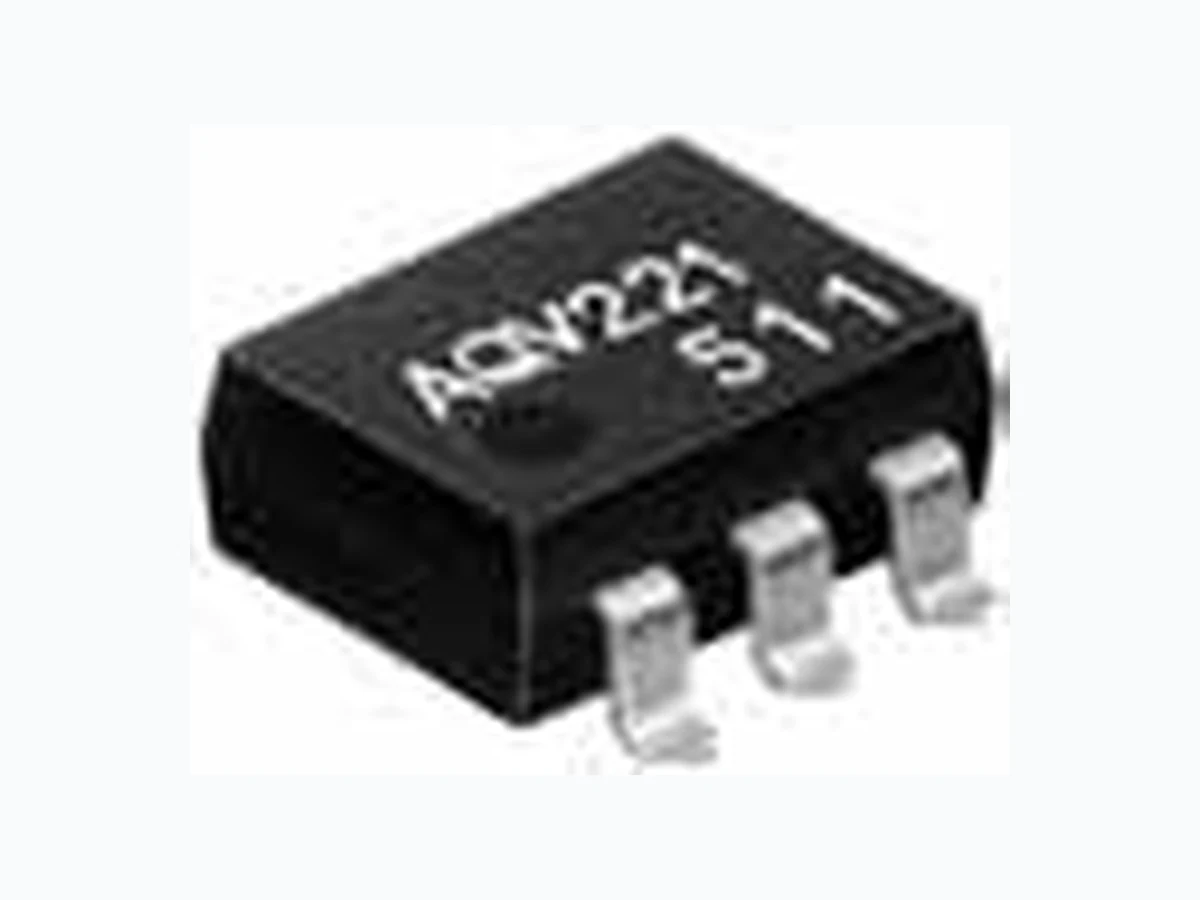
Panasonic Corporation Automation Controls Business Unit industrial.panasonic.com/ac/e RF 1 Form A (AQV22❍) ASCTB152E 201201-T TYPES *Indicate the peak AC and DC values. Note: The surface mount terminal shape indicator “A” and the packing style indicator “X” or “Z” are not marked on the device. RATING DIP6-pin type suited for radio frequent switching RF 1 Form A (AQV22❍) Output rating* Package Part No. Packing quantity Load voltage Load current Through hole terminal Surface-mount terminal Tube packing style Tape and reel packing style Tube Tape and reelPicked from the 1/2/3-pin side Picked from the 4/5/6-pin side AC/DC dual use
40 V 80 mA
AQV221 AQV221A AQV221AX AQV221AZ 1 tube contains: 50 pcs. 1 batch contains: 500 pcs. 1,000 pcs
80 V 50 mA AQV225 AQV225A AQV225AX AQV225AZ
FEATURES
- High frequency characteristics with low capacitance between output terminals Low output capacitance: typ. 4.8 pF Isolation loss: 40 dB or more (at 1 MHz) (AQV225) 2. High speed switching Turn on time: typ. 0.1 ms Turn off time: typ. 0.03 ms 3. Low-level off state leakage current of typ. 0.03 nA 4. Controls low-level analog signals PhotoMOS features extremely low closed-circuit offset voltages to enable control of small analog signals without distortion. TYPICAL APPLICATIONS 1. Measuring instruments Scanner, IC checker, Board tester, etc. 2. Audio visual equipment CD, VCR 3. Security equipment 8.8 6.4 3.6 8.8 6.4 3.9 .346 .252 .142 .346 .252 .154 RoHS compliant Height includes standoff 1. Absolute maximum ratings (Ambient temperature: 25°C 77°F) Item Symbol Type of connection AQV221(A) AQV225(A) Remarks Input LED forward current I F 50 mA LED reverse voltage V R 5 V Peak forward current I FP 1 A f = 100 Hz, Duty factor = 0.1% Power dissipation P in 75 mW Output Load voltage (peak AC) V L 40 V 80 V Continuous load current I L A 0.08 A 0.05 A A connection: Peak AC, DC B, C connection: DCB 0.09 A 0.06 A C 0.12 A 0.075 A Peak load current I peak 0.18 A 0.15 A A connection: 100 ms (1 shot), V L = DC Power dissipation P out 230 mW Total power dissipation P T 280 mW I/O isolation voltage V iso 1,500 V AC Temperature limits Operating T opr –40°C to +85°C –40°F to +185°F Non-condensing at low temperatures Storage T stg –40°C to +100°C –40°F to +212°F
Panasonic Corporation Automation Controls Business Unit industrial.panasonic.com/ac/e RF 1 Form A (AQV22❍) ASCTB152E 201201-T 2. Electrical characteristics (Ambient temperature: 25°C 77°F) *Turn on/Turn off time RECOMMENDED OPERATING CONDITIONS Please obey the following conditions to ensure proper device operation and resetting. ■ For Dimensions. ■ For Schematic and Wiring Diagrams. ■ For Cautions for Use. ■ These products are not designed for automotive use. If you are considering to use these products for automotive applications, please contact your local Panasonic Corporation technical representative. For more information. Item Symbol Type of connection AQV221(A) AQV225(A) Remarks Input LED operate current Typical IFon — 0.9 mA IL= Max.Maximum 3 mA LED turn off current Minimum IFoff — 0.4 mA IL= Max.Typical 0.85 mA LED dropout voltage Typical VF — 1.25 V (1.14 V at IF = 5 mA) IF = 50 mAMaximum 1.5 V Output On resistance Typical Ron A 22 Ω 36 Ω IF = 5 mA IL = Max. Within 1 s on timeMaximum 35 Ω 50 Ω Typical Ron B 13 Ω 21 Ω IF = 5 mA IL = Max. Within 1 s on timeMaximum 18 Ω 25 Ω Typical Ron C 6.5 Ω 10.5 Ω IF = 5 mA IL = Max. Within 1 s on timeMaximum 9 Ω 12.5 Ω Output capacitance Typical Cout — 5.6 pF 4.8 pF IF = 0 mA VB = 0 V f = 1 MHzMaximum 8 pF Off state leakage current Typical ILeak — 0.03 nA IF = 0 mA VL = Max.Maximum 10 nA Transfer characteristics Turn on time* Typical Ton — 0.1 ms IF = 5 mA IL = Max.Maximum 0.3 ms Turn off time* Typical Toff — 0.03 ms IF = 5 mA IL = Max.Maximum 0.1 ms I/O capacitance Typical Ciso — 0.8 pF f = 1 MHz VB = 0 VMaximum 1.5 pF Initial I/O isolation resistance Minimum R iso — 1,000 M Ω 500 V DC Item Symbol Recommended value Unit Input LED current I F 5m A Ton Input Output 10% 90% Toff
Panasonic Corporation Automation Controls Business Unit industrial.panasonic.com/ac/e RF 1 Form A (AQV22❍) ASCTB152E 201201-T REFERENCE DATA 1. Load current vs. ambient temperature characteristics Allowable ambient temperature: –40 °C to +85°C –40°F to +185°F Type of connection: A 2. On resistance vs. ambient temperature characteristics Measured portion: between terminals 4 and 6; LED current: 5 mA; Load voltage: Max. (DC); Continuous load current: Max. (DC) 3. Turn on time vs. ambient temperature characteristics Sample: AQV221, AQV225; LED current: 5 mA; Load voltage: Max. (DC); Continuous load current: Max. (DC) 100 0 0 –40 20 40 60 80 85–20 AQV221 AQV225 Ambient temperature, °C Load current, mA 0 –40 20 40 60 8085 –20 AQV225 AQV221 Ambient temperature, °C On resistance, Ω 0.5 0.4 0.3 0.2 0.1 0 0 –40 20 40 60 8085–20 Ambient temperature, °C Turn on time, ms 4. Turn off time vs. ambient temperature characteristics Sample: AQV221, AQV225; LED current: 5 mA; Load voltage: Max. (DC); Continuous load current: Max. (DC) 5. LED operate current vs. ambient temperature characteristics Sample: AQV221, AQV225; Load voltage: Max. (DC); Continuous load current: Max. (DC) 6. LED turn off current vs. ambient temperature characteristics Sample: AQV221, AQV225; Load voltage: Max. (DC); Continuous load current: Max. (DC) 0.2 0.1 0 0 –40 20 40 60 8085–20 Turn off time, ms Ambient temperature, °C 0 0 –40 20 40 60 8085 –20 Ambient temperature, °C LED operate current, mA 0 0 –40 20 40 60 8085 –20 Ambient temperature, °C LED turn off current, mA 7. LED dropout voltage vs. ambient temperature characteristics Sample: AQV221, AQV225; LED current: 5 to 50 mA 8. Current vs. voltage characteristics of output at MOS portion Measured portion: between terminals 4 and 6; Ambient temperature: 25°C 77°F 9. Off state leakage current vs. load voltage characteristics Measured portion: between terminals 4 and 6; Ambient temperature: 25°C 77°F 1.5 1.4 1.3 1.2 1.1 1.0 0 –20 20 40 60 80 85 –40 50mA 30mA 20mA 10mA 5mA Ambient temperature, °C LED dropout voltage, V –1.0 1.0 2.0 –2.0 –100 100 AQV221 AQV225 –80 –60 –40 –20 Voltage, V Current, mA –12 02 010 30 50 70 40 60 80 AQV221 AQV225 Load voltage, V Off state leakage current, A
Panasonic Corporation Automation Controls Business Unit industrial.panasonic.com/ac/e RF 1 Form A (AQV22❍) ASCTB152E 201201-T 10. Turn on time vs. LED forward current characteristics Sample: AQV221, AQV225; Measured portion: between terminals 4 and 6; Load voltage: Max. (DC); Continuous load current: Max. (DC); Ambient temperature: 25°C 77°F 11. Turn off time vs. LED forward current characteristics Sample: AQV221, AQV225; Measured portion: between terminals 4 and 6; Load voltage: Max. (DC); Continuous load current: Max. (DC); Ambient temperature: 25°C 77°F 12. Output capacitance vs. applied voltage characteristics Measured portion: between terminals 4 and 6; Frequency: 1 MHz; Ambient temperature: 25°C 77°F0.3 0.2 0.1 10 20 30 40 50 0 LED forward current, mA Turn on time, ms 0.05 0.04 0.03 0.02 0.01 0 10 20 30 40 50 0 LED forward currnt, mA Turn off time, ms 002 010 30 50 70 40 60 80 AQV221 AQV225 Applied voltage, V Output capacitance, pF 13. Isolation vs. frequency characteristics (50Ω impedance) Measured portion: between terminals 4 and 6; Frequency: 1 MHz; Ambient temperature: 25°C 77°F 14. Insertion loss vs. frequency characteristics (50Ω impedance) Measured portion: between terminals 4 and 6; Frequency: 1 MHz; Ambient temperature: 25°C 77°F 100 0 10 5 106 107 AQV225AQV221 Frequency, Hz Isolation, dB 105 106 107 Frequency, Hz Isolation, dB AQV221 AQV225