
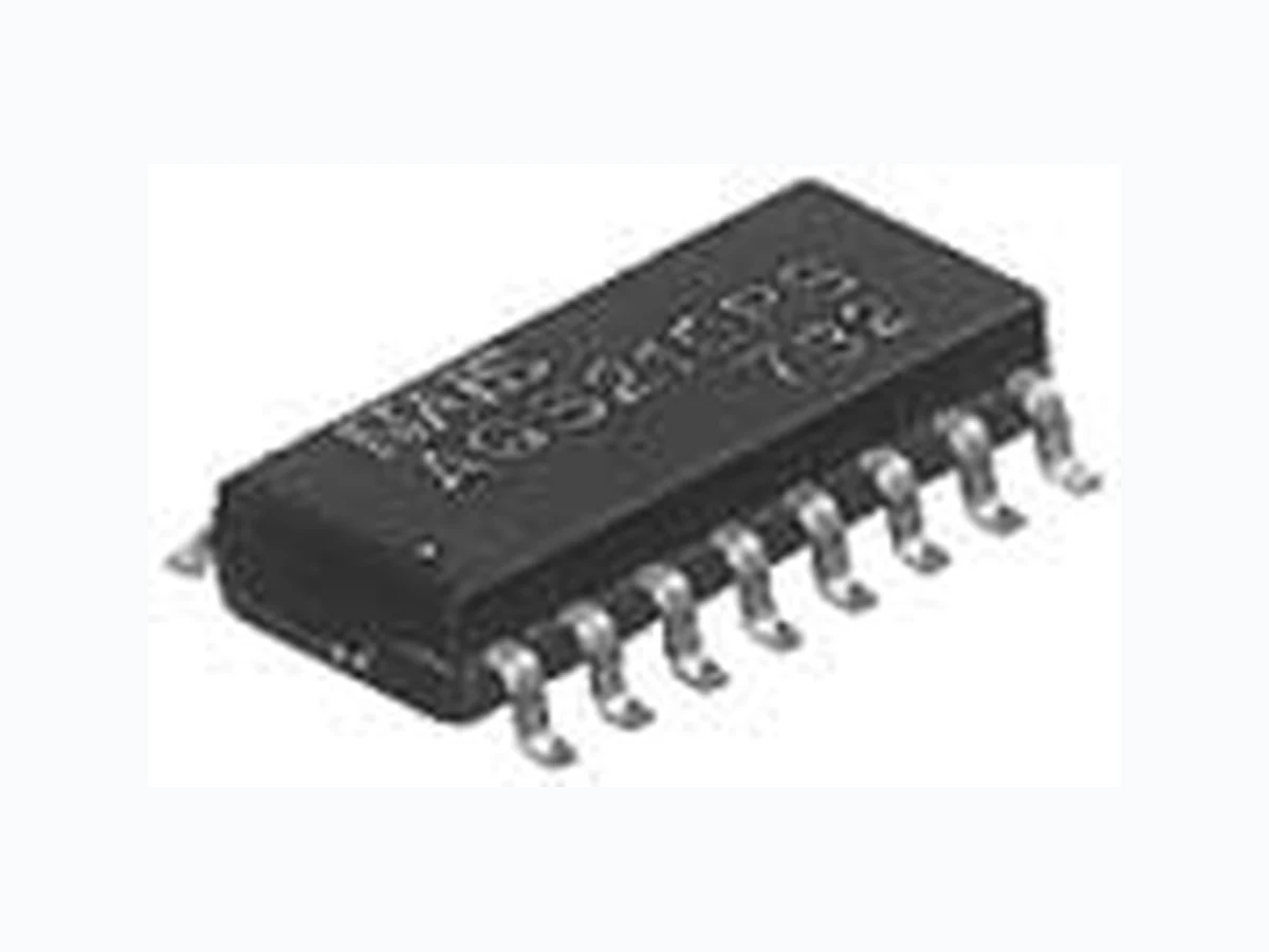
AQS210PS NAIS
Document overview
- Manufacturer or author: Provided By digicamel.com
- PDF pages: 4
Technical content
GU PhotoMOS (AQS210PS) GU PhotoMOS (AQS210PS) DAA (Data Access Arrangement) circuit package. SOP 16-pin type. 2.1 .083 4.4 .173 10.37 .408
FEATURES
- DAA (Data Access Arrangement) circuit package /L55443 /L55444 /L55445 /L55446 (1) PhotoMOS Relay (for hookswitch, dial pulse) (2) Optocoupler (for ring detection) (3) Darlington for transistor (for electronic inductance) (4) Diode bridge (for polarity protection) 2. Ultra-small package size 2. SO package 16-Pin type in super miniature design The device comes in a super-miniature SO package 16-Pin type measuring (W)4.4 (L)10.37 (H) 2.1mm (W).173 (L).408 (H).083inch 3. Ideal for PC card and Fax/Modem
applications
The small size provides additional space for increased functionality. The new device has been specifically designed for the PCMCIA embedded and handheld device markets. 4. Tape and reel The device comes standard in tape and reel (1,000 pcs./reel) for use with automatic insertion machines. 5. Internal zener diode type also available TYPICAL APPLICATIONS
- PCMCIA Modem card (Data/fax modem)
- Laptop and notebook computers
- PDA's
- Mobile computing equipment
- Medical equipment
- Security systems
- Meters (Water, Gas, Vending machine) TYPES * Indicate the peak AC and DC values. Notes: (1) Tape package is the standard packing style. Also available in tube. (Part No. suffix “X” or “Z” is not needed when ordering; Tube: 50 pcs.; Case: 1,000 pcs.) (2) For space reasons, the package type indicator “X” and “Z” are omitted from the seal. Type Relay portion Output rating* Part No. Packing quantity in tape and reelLoad voltage Load current Picked from the 1/2/3/4/5/6/7/8-pin side Picked from the 9/10/11/12/13/14/15/16-pin side AC/DC type 350V 120mA AQS210PSX AQS210PSZ 1,000 pcs. RATING 1. Absolute maximum ratings (Ambient temperature: 25 C 77 1) Relay portion (2, 3, 15, 16 pins) 2) Detector portion (7, 8, 9, 10 pins) 3) Bridge rectifier portion (10, 11, 12, 15 pins) Item Symbol AQS210PS Remarks Input LED forward current I F 50mA LED reverse voltage V R Peak forward current I FP 1A f=100 Hz, Duty factor=0.1% Power dissipation P in 75mW Output Load voltage (peak AC) V L 350V Continuous load current I L 0.12A Peak AC,DC Peak load current I peak 0.36A 100 ms (1 shot), V L = DC Power dissipation P out 400mW Item Symbol AQS210PS Remarks Input LED forward current I F 50mA Peak forward current I FP 1A f = 100 Hz, Duty factor=0.1% Power dissipation P in 75mW Output Voltage between collector and emitter BV CEO 30V Power dissipation P out 150mW Item Symbol AQS210PS Remarks Forward current I F 140mA Peak forward current I FP 500mA t=10ms Reverse voltage V R 100V mm inch TESTING
GU PhotoMOS (AQS210PS) 4) Darlington portion (12, 13, 14 pins) 5) Others 2. Electrical characteristics (Ambient temperature: 25 C 77 1) Relay portion (2, 3, 15, 16 pins) Note: Recommendable LED forward current I F =5mA. Item Symbol AQS210PS Remarks Output voltage BV CEC 40V Collector current I C 120mA V CE =3.5V Power dissipation P out 500mW Item Symbol AQS210PS Remarks Total power dissipation P T 650mW I/O isolation voltage V iso 1500V AC Temperature limits Operating T opr –40 C to +85 C –40 F to +185 F Non-condensing at low temperatures Storage T stg –40 C to +100 C –40 F to +212 F Item Symbol AQS210PS Condition Input LED operate current Typical I Fon 0.9mA I L =Max.Maximum 3mA LED turn off current Minimum I Foff 0.4mA I L =Max.Typical 0.8mA LED dropout voltage Typical V F 1.25 (1.14 V at I F =5mA) I F =50mAMaximum 1.5V Output On resistance Typical R on Ω I F =5mA I L =Max. Within 1 s on timeMaximum 25 Ω Off state leakage current Maximum I Leak µ A I F V L =Max. Transfer characteristics Turn on time* Typical T on 0.23ms I F =5mA I L =Max.Maximum 2.0ms Turn off time* Typical T off 0.04ms I F =5mA I L =Max.Maximum 1.0ms 2) Detector portion (7, 8, 9, 10 pins) 3) Diode Bridge portion (10, 11, 12, 15 pins) Item Symbol AQS210PS Condition Input LED operate current Typical I Fon 2mA I C =2mA V CE =0.5VMaximum 6mA LED turn off current Minimum I Foff µ A I C µ A V CE =5VTypical 35 µ A LED dropout voltage Typical V F 1.14 (1.25 V at I F =50mA) I F =5mAMaximum 1.5V Output Saturation voltage Typical V on 0.08V I F =15mA I C =2mAMaximum 0.5V Off state leakage current Typical I CEO 0.01nA I F V CE =5VMaximum 500nA Current transfer ratio Minimum — 33% I F =5mA V CE =0.5VTypical 100% Transfer characteristics Turn on time* Typical T on 0.01ms I F =5mA V CE =5V I C =2mA Turn off time* Typical T off 0.03ms I F =5mA V CE =5V I C =2mA Item Symbol AQS210PS Condition Forward dropout voltage Typical I F 0.9V I F =120mAMaximum 1.2V Reverse leakage current Maximum I R µ AV R =100V
GU PhotoMOS (AQS210PS) 4) Darlington transistor portion (12, 13, 14 pins) 5) Others *Turn on/Turn off time For type of connection, see page 33. Item Symbol AQS210PS Condition Saturation voltage Typical V CE(SAT) 0.73V I C =120mAMaximum 1.5V Collector leakage current Maximum I CEX µ AV CE =10V, I B =0mA DC current gain Minimum h FE 10,000 I C =120mA V CE =10VTypical 30,000 Total harmonic distortion Maximum — -80dB I C =40mA, f o =300Hz @-10dBm Item Symbol AQS210PS Condition Transfer characteristics I/O capacitance Typical C iso 0.8pF —Maximum 1.5pF Initial I/O isolation resistance Minimum R iso 1,000M Ω 500V DC Ton Toff 90% 10% Input Output REFERENCE DATA [1] Relay portion (2, 3, 15, 16 pins) [AQS210PS] 1. Load current vs. ambient temperature characteristics Allowable ambient temperature: –40 C to +85 C –40 F to +185 F 2. On resistance vs. ambient temperature characteristics Measured portion: between terminals 15 and 16 LED current: 5 mA; Load voltage: Max. (DC); Continuous load current: Max. (DC) 3. Turn on time vs. ambient temperature characteristics LED current: 5 mA; Load voltage: Max. (DC); Continuous load current: Max. (DC) 100 120 –40 0 –20 20 40 60 8085 Ambient temperature, °C Load current, mA –40 0 –20 20 40 60 8085 Ambient temperature, °C On resistance, Ω 0.2 0.4 0.6 0.8 1.0 –40 0 –20 20 40 60 8085 Ambient temperature, °C Turn on time, ms 4. Turn off time vs. ambient temperature characteristics LED current: 5 mA; Load voltage: Max. (DC); Continuous load current: Max. (DC) 5. LED operate current vs. ambient temperature characteristics Load voltage: Max. (DC); Continuous load current: Max. (DC) 6. LED turn off current vs. ambient temperature characteristics Load voltage: Max. (DC); Continuous load current: Max. (DC) 0.4 0.3 0.2 0.1 0 –40 0 20 40 60 8085–20 Ambient temperature, °C Turn off time, ms –40 0 –20 20 40 60 8085 Ambient temperature, °C LED operate current, mA –40 0 –20 20 40 60 8085 Ambient temperature, °C LED turn off current, mA I For Dimensions, see Page 28. I For Schematic and Wiring Diagrams, see Page 33. I For Cautions for Use, see Page 36.
GU PhotoMOS (AQS210PS) 7. LED dropout voltage vs. ambient temperature characteristics LED current: 5 to 50 mA 8. Voltage vs. current characteristics of output at MOS portion Measured portion: between terminals 15 and 16 Ambient temperature: 25 C 77 F 9. Off state leakage current Measured portion: between terminals 15 and 16 Ambient temperature: 25 C 77 F 1.0 1.1 1.2 1.3 1.4 1.5 –40 0 –20 20 40 60 8085 50 mA 30 mA 20 mA 10 mA 5 mA Ambient temperature, °C LED dropout voltage, V 2345 120 100 –20 –40 –60 –80 –100 –120 Voltage, V Current, mA 0 2 04 06 08 0 1 0 0 –12 Load voltage, V Off state leakage current, A 10. LED forward current vs. turn on time characteristics Measured portion: between terminals 15 and 16 Load voltage: Max. (DC); Continuous load current: Max. (DC); Ambient temperature: 25 C 77 F 11. LED forward current vs. turn off time characteristics Measured portion: between terminals 15 and 16 Load voltage: Max. (DC); Continuous load current: Max. (DC); Ambient temperature: 25 C 77 F 12. Applied voltage vs. output capacitance characteristics Measured portion: between terminals 15 and 16 Frequency: 1 MHz; Ambient temperature: 25 C 77 F 0 1 02 03 04 05 06 00 0.2 0.4 0.6 0.8 1.0 1.2 1.4 LED forward current, mA Turn on time, ms 0 1 02 03 04 05 06 00 0.02 0.04 0.06 0.08 0.10 LED forward current, mA Turn off time, ms 0 1 02 03 04 05 0 Applied voltage, V Output capacitance, pF [2] Detector portion (7, 8, 9, 10 pins) 1. Output loss vs. ambient temperature characteristics Allowable ambient temperature: –40 C to +85 C –40 F to +185 F 2. Relative output current vs. ambient temperature characteristics Measured portion: between terminals 7 and 8 I F = 5 mA, V CE = 0.5 V DC 3. LED dropout voltage vs. ambient temperature characteristics LED current: 5 to 50 mA –40 –20 0 20 40 60 8085 1000 100 150 200 Ambient temperature, °C Output loss, mW –40 –20 0 20 40 60 8085 100 100 150 Ambient temperature, °C Relative output current, % 1.0 1.1 1.2 1.3 1.4 1.5 –20–40 0 20 40 60 8085 50 mA 30 mA 20 mA 10 mA 5 mA Ambient temperature, °C LED dropout voltage, V 4-1. Collector current vs. voltage between collector and emitter characteristics (I C CE Measured portion: between terminals 7 and 8 Ambient temperature: 25 C 77 F 4-2. Collector current vs. voltage between collector and emitter characteristics (I C CE Measured portion: between terminals 7 and 8 Ambient temperature: 25 C 77 F 5. Off state leakage current Measured portion: between terminals 7 and 8 I F = 0 mA T a = 25 C 77 F 2468 1 0 PC (Max.) IF=50 mA IF=40 mA IF=30 mA IF=20 mA IF=10 mA IF=5 mA Voltage between collector and emitter, V Collector current, mA IF=50 mA IF=40 mA IF=30 mA IF=20 mA IF=10 mA IF=5 mA Voltage between collector and emitter, V Collector current, mA 0 1 02 03 010 –12 Voltage between collector and emitter, V Off state leakage current, A