
AP17E070064A TAOGLAS
Document overview
- Manufacturer or author: Provided By www.digicamel.com(FREE DATASHEET DOWNLOAD SITE)
- PDF pages: 9
Technical content
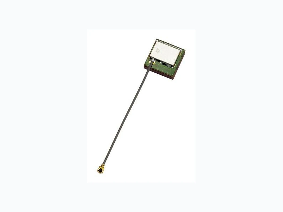
SPE-11-8-144/C Page 1 of 9 SPECIFICATION Part No. : AP17E.07.0064A Product Name : 17mm One Stage GPS/GALILEO Active Patch Antenna Module with Front End SAW Filter Features : 17mm*17mm*6.3mm 64mm 1.13 IPEX MHFI Wide Voltage 1.8V~5.5V 15dB LNA Tested in Free space ROHS Compliant
SPE-11-8-144/C Page 2 of 9 1. Introduction The AP.17E is a one stage 17mm active patch antenna that has been designed specifically for embedded (inside device) integration with GPS/GALILEO receiver modules. The AP.17E combines a 17*17*4mm advanced low profile ceramic patch antenna with a one stage LNA and a front-end SAW filter with ultra thin coaxial cable. It comes with it’s own integrated ground-plane. The front end SAW filter reduces the risks where there is a cellular transmitter nearby of interference from out of band frequencies which can cause LNA burn-out, saturation, or radiated spurious emissions. The antenna can work on a wide input voltage from 1.8V to 5.5V with best in class power consumption figures. If further tuning and optimization specific to a customer device is required Taoglas offers a custom tuned and optimized part service. Contact sales@taoglas.com for more information. Cables and connectors can be customized according to request. ANTENNA SAW Filter LNA I-PEX +cable
SPE-11-8-144/C Page 3 of 9 2. Specification ELECTRICAL Input Voltage Min:1.8V Typ.: 3.0V Max: 5.5V Frequency Range 1575.42MHz +/- 1.023 MHz Gain -1.0dBic Typ. @zenith Polarization RHCP Axial ratio Max 3.0dB@zenith Frequency Range 1575.42MHz +/- 1.023 MHz Gain (With LNA) At 90° At 5.5V 16 ± 3dBic At 3.0V 15 ± 3dBic At 1.8V 12 ± 3dBic Output Impedance 50Ω LNA Frequency 1575.42 ± 1.023MHz Outer Band Attenuation F0=1575.42MHz F0±30MHz 2dB min. F0±50MHz 18dB min. F0±100MHz 25dB min. Output Impedance 50Ω Output VSWR 2.0 Max Pout at 1dB Gain Compression point Typ. -2dBm Min. -6dBm LNA Gain, Power Consumption and Noise Figure Voltage LNA Gain (Typ) Power Consumption Noise Figure Typ (mA) Typ Min. 1.8V 13dB 1.6mA 2.5dB Typ. 3.0V 16dB 3.5mA 2.5dB Max. 5.5V 17dB 7.6mA 2.6dB
SPE-11-8-144/C Page 4 of 9 MECHANICAL Dimensions 17mm*17mm*6.3mm RF Cable Ø1.13 RF Coaxial Cable L=64mm2.5mm RF Connector IPEX MHFI ENVIRONMENTAL Operation Temperature -40°C to + 85°C Storage Temperature -40°C to + 85°C Relative Humidity 40% to 95%
SPE-11-8-144/C Page 5 of 9 2.1. LNA Gain and Out Band Rejection @3.0V 2.2. LNA Noise Figure @3.0V
SPE-11-8-144/C Page 6 of 9 3. Radiation Patterns XY Plane XZ Plane YZ Plane
SPE-11-8-144/C Page 7 of 9 4. Plugs Usage Precautions 4.1. Mating / Unmating (1) To disconnect connectors, insert the end portion of I-PEX under the connector flanges and pull off vertically, in the direction of the connector mating axis. (2) To mate the connectors, the mating axes of both connectors must be aligned and the connectors can be mated. The "click" will confirm fully mated connection. Do not attempt to insert on an extreme angle. 4.2. Pull forces on the cable after connectors are mated After the connectors are mated, do not apply a load to the cable in excess of the values indicated in the diagram below.
SPE-11-8-144/C Page 8 of 9 5. Mechanical Drawing (Unit: mm)
SPE-11-8-144/C Page 9 of 9 6. Packaging Taoglas makes no warranties based on the accuracy or completeness of the contents of this docume nt and reserves the right to make changes to specifications and product descriptions at any time without notice. Taoglas reserves all rights to this document and the information contained herein. Reproduction, use or disclosure to third parties without express permission is strictly prohibited. Copyright © Taoglas Ltd.