

 Download PDF
AMCA72-2R470G-S1F ABRACON
Document overview
- Manufacturer or author: Provided By digicamel.com
- PDF pages: 15
Technical content
Features
- Miniaturized in size: 7 x 2 x 1 mm
- Compact & Low-Profile
- Low return loss of: ≤ -13.9 dB
- Peak Gain: 3.3 dBi
- Average Total Efficiency: -0.4 dB (92%)
- Linear Polarization
- Surface Mount (SMD)
Applications
- Bluetooth® / ZigBee® / Thread / Matter / Wi-Fi®
- Bluetooth® / Wi-Fi® Modules
- Consumer Hearables & Wearables
- Medical Wearables & Tele-Medicine
- Smart Home & Smart Building
- Asset Tracking & Telematics
- Smart Metering
- Intelligent Lighting
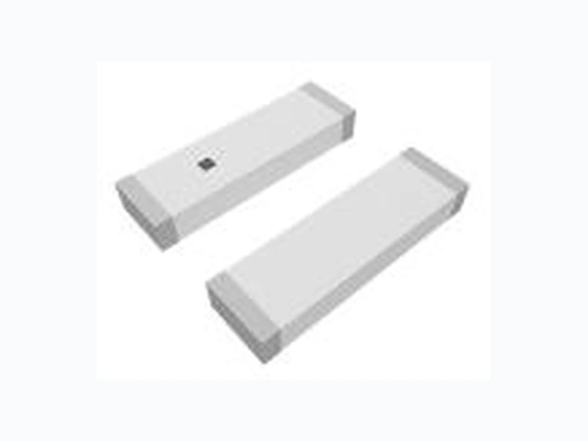
- Wireless Remote Control Product Image
REVISION E: 02-10-25 www.abracon.com 2.4GHz Chip Antenna AMCA72-2R470G-S1F 7.0 x 2.0 x 1.0 mm RoHS/RoHS II Compliant MSL Level = 1 Request Samples Check Inventory
5101 Hidden Creek Ln Spicewood TX 78669
Phone: 512-371-6159 | Fax: 512-351-8858 For terms and conditions of sales, please visit: Electrical Specification Note: All measurements were performed using the evaluation board “AMCA72-2R470G-S1F-EVB” in a free -space environment. Actual performance may vary depending on factors such as the ground plane, specific application, and surrounding environment. Mechanical Specification Environmental Specification
Ordering Information
Parameter Specification Unit Operating Frequency 2400 - 2500 MHz Return Loss ≤ -13.9 dB VSWR ≤ 1.5 :1 Polarization Linear - Peak Gain 3.3 dBi Minimum Total Efficiency -0.6 (88) dB (%) Average Total Efficiency -0.4 (92) dB (%) Maximum Total Efficiency -0.2 (95) dB (%) Impedance 50 Ω Radiation Pattern Omni-directional - Input Power < 3 W Parameter Specification Antenna Dimension 7.0 x 2.0 x 1.0 mm Evaluation board Dimension 51 x 18 mm Recommended Ground Clearance for Antenna 18 x 9.5 mm Mounting Type Surface Mount Material(s) Ceramic Parameter Specification Operating and Storage Temperature (individual chip without packing) -40⁰C to +85⁰C Packaging Storage Temperature -10⁰C to +40⁰C Packaging Storage Relative Humidity 70% (Max.) Part Number Description AMCA72-2R470G-S1F Antenna Component on Cut Tape AMCA72-2R470G-S1F-T4 Antenna Component on Tape & Reel AMCA72-2R470G-S1F-EVB Evaluation Kit
REVISION E: 02-10-25 www.abracon.com 2.4GHz Chip Antenna AMCA72-2R470G-S1F 7.0 x 2.0 x 1.0 mm RoHS/RoHS II Compliant MSL Level = 1 Request Samples Check Inventory Phone: 512-371-6159 | Fax: 512-351-8858 For terms and conditions of sales, please visit: Product Dimensions and Terminal Configuration Unit: Inches [mm] Symbol Description Antenna Feed NC (not connected) M Mark
REVISION E: 02-10-25 www.abracon.com 2.4GHz Chip Antenna AMCA72-2R470G-S1F 7.0 x 2.0 x 1.0 mm RoHS/RoHS II Compliant MSL Level = 1 Request Samples Check Inventory Phone: 512-371-6159 | Fax: 512-351-8858 For terms and conditions of sales, please visit: Recommended PCB layout “AMCA72-2R470G-S1F-EVB” If there are several layers in the PCB, there is an advantage to add vias for smooth interconnection of the ground areas to avoid splits in the ground plane. It is also important that the ground clearance is respected through all layers of the PCB. It is recommended to implement a matching network to optimize the antenna impedance in your application. Rotated detailed view of antenna pads and copper clearance: Unit: mm Transmission Line The transmission line should be kept as short as possible and be designed to have a characteristic impedance of Ω Abracon recommends using a Co-Planar Waveguide with Ground (CPWG), which dimensions can be derived by any trusted calculator, using the correct input for PCB materials and layer stack-up.
REVISION E: 02-10-25 www.abracon.com 2.4GHz Chip Antenna AMCA72-2R470G-S1F 7.0 x 2.0 x 1.0 mm RoHS/RoHS II Compliant MSL Level = 1 Request Samples Check Inventory Phone: 512-371-6159 | Fax: 512-351-8858 For terms and conditions of sales, please visit: Alternative PCB layout “Corner Mount” If there are several layers in the PCB, there is an advantage to add vias for smooth interconnection of the ground areas to avoid splits in the ground plane. It is also important that the ground clearance is respected through all layers of the PCB. It is recommended to implement a matching network to optimize the antenna impedance in your application. The transmission line should be kept as short as possible and be designed to have a characteristic impedance of Ω Rotated detailed view of antenna pads and copper clearance: Unit: mm
REVISION E: 02-10-25 www.abracon.com 2.4GHz Chip Antenna AMCA72-2R470G-S1F 7.0 x 2.0 x 1.0 mm RoHS/RoHS II Compliant MSL Level = 1 Request Samples Check Inventory Phone: 512-371-6159 | Fax: 512-351-8858 For terms and conditions of sales, please visit: Measurement Setup The antenna measurements were all done in free space, with the chip antenna implemented on its evaluation board (AMCA72-2R470G-S1F-EVB) that has a PCB size of 51 x 18 mm: Measurements were also done with the antenna mounted on a PCB with the Alternative PCB layout “Corner ount” that has a PCB size of 42 x 18 mm: Reflection Characteristics – Return Loss
REVISION E: 02-10-25 www.abracon.com 2.4GHz Chip Antenna AMCA72-2R470G-S1F 7.0 x 2.0 x 1.0 mm RoHS/RoHS II Compliant MSL Level = 1 Request Samples Check Inventory Phone: 512-371-6159 | Fax: 512-351-8858 For terms and conditions of sales, please visit: Radiation Characteristics – Total Efficiency (dB) Radiation Characteristics – Total Efficiency (%)
REVISION E: 02-10-25 www.abracon.com 2.4GHz Chip Antenna AMCA72-2R470G-S1F 7.0 x 2.0 x 1.0 mm RoHS/RoHS II Compliant MSL Level = 1 Request Samples Check Inventory Phone: 512-371-6159 | Fax: 512-351-8858 For terms and conditions of sales, please visit: Radiation Characteristics – Maximum Gain Radiation Characteristics – 3D Pattern @ 2450 MHz (AMCA72-2R470G-S1F-EVB) Unit: dBi
REVISION E: 02-10-25 www.abracon.com 2.4GHz Chip Antenna AMCA72-2R470G-S1F 7.0 x 2.0 x 1.0 mm RoHS/RoHS II Compliant MSL Level = 1 Request Samples Check Inventory Phone: 512-371-6159 | Fax: 512-351-8858 For terms and conditions of sales, please visit: Radiation Characteristics – 2D Pattern @ 2450 MHz (AMCA72-2R470G-S1F-EVB) XY-plane: XZ-plane: YZ-plane: VP: Vertical Polarization HP: Horizontal Polarization Unit: dBi
REVISION E: 02-10-25 www.abracon.com 2.4GHz Chip Antenna AMCA72-2R470G-S1F 7.0 x 2.0 x 1.0 mm RoHS/RoHS II Compliant MSL Level = 1 Request Samples Check Inventory Phone: 512-371-6159 | Fax: 512-351-8858 For terms and conditions of sales, please visit: Radiation Characteristics – 3D Pattern @ 2450 MHz (Corner Mount) Unit: dBi
REVISION E: 02-10-25 www.abracon.com 2.4GHz Chip Antenna AMCA72-2R470G-S1F 7.0 x 2.0 x 1.0 mm RoHS/RoHS II Compliant MSL Level = 1 Request Samples Check Inventory Phone: 512-371-6159 | Fax: 512-351-8858 For terms and conditions of sales, please visit: Radiation Characteristics – 2D Pattern @ 2450 MHz (Corner Mount) XY-plane: XZ-plane: YZ-plane: VP: Vertical Polarization HP: Horizontal Polarization Unit: dBi
REVISION E: 02-10-25 www.abracon.com 2.4GHz Chip Antenna AMCA72-2R470G-S1F 7.0 x 2.0 x 1.0 mm RoHS/RoHS II Compliant MSL Level = 1 Request Samples Check Inventory Phone: 512-371-6159 | Fax: 512-351-8858 For terms and conditions of sales, please visit: Evaluation Board Outline & Matching Circuit The evaluation board (AMCA72-2R470G-S1F-EVB) is developed to simplify antenna testing and evaluation. It has an arbitrary size of 51 x 18 mm and includes an SMA connector. The purpose is to give a reference design for an optimal antenna implementation. The evaluation board can also be used to test other implementations by cutting and soldering the PCB into any device. Evaluation board outline The evaluation board has a matching circuit implemented next to the antenna. This is aimed to enable optimization possibilities for the user. The component positions are sized for 0402 (1005 metric) SMD components. The antenna requires a matching circuit to fine -tune the resonant frequency and achieve optimal balance. The evaluation board is pre -tuned for optimal performance in the 2.4 –2.5 GHz range using the components listed below (equivalents may be used): X1 = 7.3 nH (Murata LQW15AN7N3G00D) X2 = 0.8 pF (Murata GJM1555C1HR80WB01D) X3 = not mounted However, it is common that the resonant frequency will shift during im plementation in an arbitrary device. Therefore, this matching may be changed with other values/components/brands for compensation of such effects. This is further described in the General Implementation Guidelines section below.
REVISION E: 02-10-25 www.abracon.com 2.4GHz Chip Antenna AMCA72-2R470G-S1F 7.0 x 2.0 x 1.0 mm RoHS/RoHS II Compliant MSL Level = 1 Request Samples Check Inventory Phone: 512-371-6159 | Fax: 512-351-8858 For terms and conditions of sales, please visit: General Implementation Guidelines The antenna can be positioned in different ways, although there are some positions which are more beneficial. The below illustration shows a typical PCB with examples on different antenna positions ; where option 1 typically yields slightly better performance, and option 2 uses less space of the PCB. The rectangular copper cutout in the footprint must extend through all layers of the PCB stack-up, ensuring there is no copper on any layer in this area . Additionally, a robust via structure around the cutout and along the edge of the ground plane is highly recommended for optimal performance. It is important to note that plastic and metal parts in close proximity to antennas may significantly affect antenna tuning and performance. For instance, a plastic housing above the antenna often causes the resonant frequency to shift downward. Since such effects are challenging to predict without detailed design information, it is recommended to measure the antenna performance in the final device after implementation. To compensate for potential frequency shifts, implementing a matching network on the antenna feed is advisable. Another general consideration for surface-mounted antennas relates to PCB population. Electrical components placed near the antenna may impact its tuning and radiation performance. To mitigate this, components in the surrounding area should be positioned b elow a topographical slope. This slope should begin at the PCB level near the antenna's designated keep-out zone and gradually increase in height as distance from the antenna grows. For technical assistance, please contact Abracon online support through our online support platform.
REVISION E: 02-10-25 www.abracon.com 2.4GHz Chip Antenna AMCA72-2R470G-S1F 7.0 x 2.0 x 1.0 mm RoHS/RoHS II Compliant MSL Level = 1 Request Samples Check Inventory Phone: 512-371-6159 | Fax: 512-351-8858 For terms and conditions of sales, please visit: Reflow Profile [JEDEC J-STD-020] Solder paste: Sn/3.0Ag/0.5Cu Profile Feature Sn-Pb Eutectic Assembly Pb-Free Assembly Preheat / soak Temperature minimum (Tsmin) 100℃ 150℃ Temperature maximum (Tsmax) 150℃ 200℃ Time (Tsmin to Tsmax) (ts) 60 – 120 sec. 60 – 90 sec. Average ramp-up rate (Tsmax to Tp) 3℃/sec. max 3℃/sec. max Liquidous temperature (TL) 183℃ 217℃ Time at Liquidous (TL) 60 – 150 sec. 60 – 150 sec. Peak package body temperature (Tp)* See Table 1 See Table 2 Time (Tp)** within 5℃ of the specified classification temperature (Tc) 20 sec. 10 sec. Ramp-down rate (Tp to Tsmax) 6℃/sec. max 6℃/sec. max Time 25℃ to peak temperature 6 min. max 8 min. max Reflow cycles 2 max 2 max *Tolerance for peak profile temperature (Tp) is defined as a supplier minimum and a user maximum. **Tolerance for time at peak profile temperature (tp) is defined as a supplier minimum and a user maximum. Table 1 SnPb Eutectic Process Classification Temperatures (Tc) Package Thickness Volume mm3 <350 Volume mm3 ≧350 <2.5mm 235℃ 220℃ ≧2.5mm 220℃ 220℃ Table 2 Pb-Free Process Classification Temperatures (Tc) Package Thickness Volume mm3 <350 Volume mm3 350-2000 Volume mm3 >2000 <1.6mm 260℃ 260℃ 260℃ 1.6mm - 2.5mm 260℃ 250℃ 245℃ >2.5mm 250℃ 245℃ 245℃
REVISION E: 02-10-25 www.abracon.com 2.4GHz Chip Antenna AMCA72-2R470G-S1F 7.0 x 2.0 x 1.0 mm RoHS/RoHS II Compliant MSL Level = 1 Request Samples Check Inventory Phone: 512-371-6159 | Fax: 512-351-8858 For terms and conditions of sales, please visit: Packaging Tape & Reel dimensions: Carrier Tape Specifications (mm) Do K0 E1 P0 T F P1 W A0 B0 Reel Qty Reel Specifications (mm) A W1 N B C ATTENTION: Abracon LLC’s products are Commercial-Off-The-Shelf (‘COTS’), which are designed, intended, and validated for use in commercial, industrial, and automotive applications. The customer is responsible for testing and verifying the performance of an Abracon solution to meet their system -level requirements.