
AGGP35F070060A ETC2
Document overview
- Manufacturer or author: Provided By www.digicamel.com(FREE DATASHEET DOWNLOAD SITE)
- PDF pages: 12
Technical content
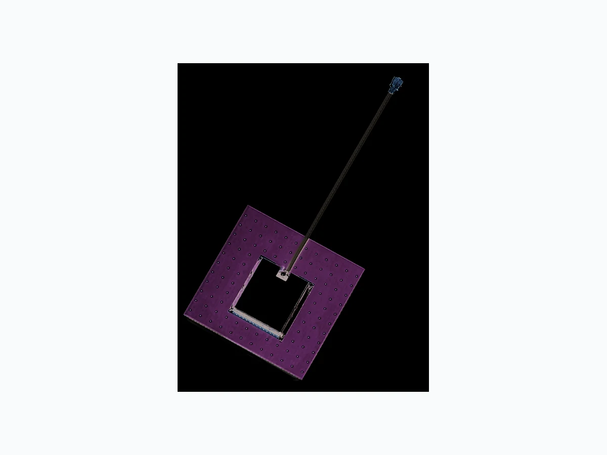
SPE-12-8-018/D/SS | page 1 of 12 AGGP.35F.07.0060A Specification Part No. AGGP.35F.07.0060A Product Name 35mm Two Stage 28dB GPS-Glonass- GNSS Active Patch Antenna Module with Front-end Saw Filter Features Industry leading GPS~GLONASS antenna performance 35*35*6.9mm (Ground Plane) 60mm Ø1.13 IPEX MHFI (U.FL) 28dB LNA Wide Input Voltage 1.8V to 5.5V Low Power Consumption ROHS Compliant Front Back
SPE-12-8-018/D/SS | page 2 of 12 The AGGP.35F GPS – Glonass- GNSS active patch antenna (along with the AGGP.25 model) is the best choice to use as an embedded antenna with the latest generation of GPS-Glonass-GNSS receivers. It utliizes a 35*35*3.5mm advanced wide-band ceramic patch antenna with optimized gain, radiation patttern and axial ratio at GPS and Glonass centre frequencies. The AGGP.35F aslo includes a two stage LNA and a front-end SAW filter to reduce out of band noise such as from nearby cellular transceiver, and improve probability of the wireless device passing radiated spurious emissions certification. Produced in TS16949 automotive quality approved facility and 100% tested for gain (S21), return loss (S11) to ensure total consistency of performance. Cable type, length and connectors can be customized and samples offered according to requirement, subject to minimum order quantities in production. Taoglas also offers custom tuning service based on minimum order quantities, contact your local regional sales office for details. The AGGP.35F consists of 2 functional blocks – the LNA and also the patch antenna. 1. Introduction ANTENNA SAW Filter LNALNA Cable & Connector
SPE-12-8-018/D/SS | page 3 of 12 2. Specification Electrical Mechanical Parameter Specification Operation Frequency 1574 ~ 1610MHz Patch Gain 1575.42MHz, 1dBic typ. @ zenith 1602MHz, 0.5dBic typ. @ zenith Overall Gain 1575.42MHz, 27 ± 3dBic typ. @ zenith 1602MHz, 28.5 ± 3dBic typ. @ zenith Axial Ratio 3.0dB max @ zenith Polarization Right Hand Circular VSWR 2.0 :1 max Impedance 50Ω LNA Gain 22dB 28dB 31dB Noise Figure 2.6dB 2.6dB 2.9dB Power Consumption 5mA 10mA 23mA Band Attenuation 15dB @ 1592 ± 140MHz Parameter Specification Antenna Dimensions 35 x 35 x 3.7mm Material Ceramic Cable 60mm 1.13 co-axial Connector IPEX MHF1 Parameter Specification Operation Temperature -40°C to 85°C Storage Temperature -40°C to 105°C Relative Humidity 40% to 95% Environmental
SPE-12-8-018/D/SS | page 4 of 12 3. LNA Gain and Out Band Rejection @3.0V Tr1 S21 Log Mag 10.00dB/ Ref 0.000dB [F2 smo] Tr1 S22 SWR 1.000/ Ref 1.000 [F2 smo] 1 Center 1.592 GHz Span 400 MHz 5/16 CorIFBW 1 kHz Ch1 Tr1 S21 1 1.5740000 GHz 28.186 dB Ch1 Tr1 S21 >2 1.6100000 GHz 27.949 dB Ch1 Tr1 S21 3 1.5920000 GHz 29.044 dB Ch1 Tr1 S21 4 1.5420000 GHz 9.0245 dB Ch1 Tr1 S21 5 1.6420000 GHz -10.035 dB Ch1 Tr1 S21 6 1.4920000 GHz 4.4105 dB Ch1 Tr1 S21 7 1.6920000 GHz -14.431 dB 40.00 30.00 20.00 10.00 0.000 -10.00 -20.00 -30.00 -40.00 -50.00 -60.00 >2 1.6100000 GHz 27.949 dB 2 6 4 1 5 7
SPE-12-8-018/D/SS | page 5 of 12 4. LNA Noise Figure @3.0V 5. Total Specification (through Antenna, LNA, Cable and Connector) Parameter Specification Frequency 1574~1610MHz Gain at 90° 1575.42MHz: 27 ± 3dBic 1602MHz: 28.5 ± 3dBic Output Impedance 50Ω Polarization RHCP Output VSWR Max 2.0 Operation Temperature -40°C to + 85°C Storage Temperature -40°C to + 85°C Relative Humidity 40% to 95% Antenna 35*35*6.9mm 140.00 GAIN Scale/ 5.000 dB -10.00 Mkr1 1.592 GHz 2.558 dB 30.030 dB Center 1.57400 GHz BW 4 MHz Points 11 Stop 1.61000 GHz Tcold 296.50 K Avgs Off Att 0/ - - dB Loss Off Corr 19.00 NFIG Scale/ 2.000 dB -1.000
SPE-12-8-018/D/SS | page 6 of 12 6. Radiation Patterns Z Y X
-10 -15 -20 -25 -30 -35 -40 -4590 270 180 SPE-12-8-018/D/SS | page 7 of 12 6. Radiation Patterns 6.1 1575.42MHz XZ & YZ Plane Pattern Peak Gain (dBic) Average Gain (dBi) 1 XZ Plane Radiation -0.6 @ 350° -3.2 2 YZ Plane Radiation -0.2 @ 0° -2.1 (unit : dBi)
-10 -15 -20 -25 -30 -35 -40 -45 SPE-12-8-018/D/SS | page 8 of 12 6.2 1602MHz XZ &YZ Plane Pattern Peak Gain (dBic) Average Gain (dBi) 1 XZ Plane Radiation 0.9 @ 337° -1.8 2 YZ Plane Radiation 0.8 @ 348° -1.2 (unit : dBi)
SPE-12-8-018/D/SS | page 9 of 12 7. Plugs Usage Precautions (1) To disconnect connectors, insert the end portion of I-PEX under the connector flanges and pull off vertically, in the direc- tion of the connector mating axis. (2) To mate the connectors, the mating axes of both connectors must be aligned and the connectors can be mated. The “click” will confirm fully mated connection. Do not attempt to insert on an extreme angle. After the connectors are mated, do not apply a load to the cable in excess of the values indicated in the diagram below. 7.I Mating / unmating
7.2 Pull forces on the cable after connectors are mated
P/N : 90192-001 RECEPTACLE PLUG RECE 2N MAX. 2N MAX. 4N MAX. Coaxial Cable
SPE-12-8-018/D/SS | page 10 of 12 NOTE: 1. Soldered area 2. Shielding case area 3. All material must be RoHS compliant. 4. The connector orientation has a fixed position to the antenna as per drawing. Name P/N Material Finish QTY 1 AGGP.35F Patch (35*35*3.7mm) AGGP.35F Ceramic Clear 1 2 1.13 Coaxial Cable OD.113.CM FEP Gray 1 3 IPEX MHF1 Connector IPEX.MHFI.113 Brass Gold 1 4 PCB FR4 0.8t Green 1
5 Shielding Case (Tin)SPTE Tin Plated 1
This drawing and its inherent design concepts are property of Taoglas. Not to be copied or given to third parties without the written consent of Taoglas. TW Design Centre A ALL Initial Design Sandy 2011/11/23 NOTE: 1.Soldered area 2.Shielding case area 3.All material must be RoHS compliant. 4.The connector orientation has a fixed position to the antenna as per drawing. Top Side Bottom Name Material Finish QTY AGGP.25F Patch(25*25*4.2mm) Ceramic Clear 1 FEP Gray2
3 GoldBrass
1.13 Coaxial Cable
14 GreenFR4 0.8tPCB
15 Tin Plated(Tin)SPTEShielding Case
AGGP.25F OD.113.CM IPEX.MHFI.113 IPEX MHFI "A" AGGP.25F B E3 Amend Logo Placement Sandy 2011/12/27 B C C2 Amend Shielding Case Drawing Sandy 2012/01/31 C This drawing and its inherent design concepts are property of Taoglas. Not to be copied or given to third parties without the written consent of Taoglas. TW Design Centre "A" NOTE: 1.Soldered area 2.Shielding case area 3.All material must be RoHS compliant. 4.The connector orientation has a fixed position to the antenna as per drawing. IPEX MHF 1 A ALL Initial Design Kiwi 2011/9/6 Top Side Bottom Name Material Finish QTY AP.10E Patch(10*10*4mm) Ceramic Clear 1 FEP Gray2
0.81 Coaxial Cable
14 Tin PlatedTin (SPTE)Shielding Case
15 GreenFR4 0.5tPCB P/N AP.10E OD.081.CM IPEX.MHFI.113 AP.10E B E2 Add LOGO Sandy 2011/11/21 B This drawing and its inherent design concepts are property of Taoglas. Not to be copied or given to third parties without the written consent of Taoglas. TW Design Centre A ALL Initial Design Sandy 2011/11/28 NOTE: 1.Soldered area 2.Shielding case area 3.All material must be RoHS compliant. 4.The connector orientation has a fixed position to the antenna as per drawing. Top Side Bottom Name Material Finish QTY AGGP.35F Patch(35*35*3.7mm) Ceramic Clear 1 FEP Gray2 14 GreenFR4 0.8tPCB AGGP.35F OD.113.CM IPEX.MHFI.113 IPEX MHFI "A" AGGP.35F B E3 Amend Logo Placement Sandy 2011/12/27 B C C2 Amend Shielding Case Drawing Sandy 2012/01/31 C C 8. Technical Drawing
SPE-12-8-018/D/SS | page 11 of 12
8.1 Connector Drawing
This drawing and its inherent design concepts are property of Taoglas. Not to be copied or given to third parties without the written consent of Taoglas. TW Design Centre A ALL Initial Design Sandy 2011/11/28 NOTE: 1.Soldered area 2.Shielding case area 3.All material must be RoHS compliant. 4.The connector orientation has a fixed position to the antenna as per drawing. Top Side Bottom Name Material Finish QTY AGGP.35F Patch(35*35*3.7mm) Ceramic Clear 1 FEP Gray2 14 GreenFR4 0.8tPCB AGGP.35F OD.113.CM IPEX.MHFI.113 IPEX MHFI "A" AGGP.35F B E3 Amend Logo Placement Sandy 2011/12/27 B C C2 Amend Shielding Case Drawing Sandy 2012/01/31 C C
SPE-12-8-018/D/SS | page 12 of 12 UNLESS OTHER SPECIFIED TOLERANCES ON: ANGLES=± HOLEDIA =± SCALE: xxxx UNIT :mm DRAWN BY: jason CHECKED BY: Jimmy DESIGNED BY: Jimmy APPROVED BY: Jimmy TITLE: AP.35F Antenna Assembly DOCUMENT AGGP.35F.07.0060A PAGE REV. NO. B ISO NO: PSP-12-8-002 PAGE 6 OF 6 5 包裝規格 5.1 每個 tray 放置 30 天線 【30pcs antennas per tray】 5.2 每 6 個 tray 包裝成 1 組, 【Stack up 6 trays together】 5.3 每箱放置 3 組 tray,總共540pcs 天線 【3 sets per box. i.e.540pcs antenna per box.】 5.4 包裝時須注意不可壓到天線,裝入需平整不可雜亂 【Antenna should be placed flat and neat, packing without pressing or damage the antenna】 5.5 清點每 tray 數量不可短缺 【Confirm the quantity in each tray】 AGGP.35F AGGP.35F 箱子 Tray 9. Packaging Taoglas makes no warranties based on the accuracy or completeness of the contents of this document and reserves the right to make changes to specifications and product descriptions at any time without notice. Taoglas reserves all rights to this document and the information contained herein. Reproduction, use or disclosure to third parties without express permission is strictly prohibited. Copyright © Taoglas Ltd. Packaged in plastic tray with foam Each comparment in tray contains 1 pcs of AGGP.35F 30 pcs of antenna per tray 6 trays together in one section 3 sections per carton 540 pcs of antenna per carton