


 Download PDF
AFE1224 TI1
Document overview
- PDF pages: 13
Technical content
Page 1
©1999 Burr-Brown Corporation
PDS-1548A
Printed in U.S.A. June, 1999
SBWS011
Page 2
SPECIFICATIONS
All specifications at 25°C, AVDD = +5V, DVDD = +3.3V, fTX = 1168kHz (E1 rate) and normal power mode, unless otherwise noted.
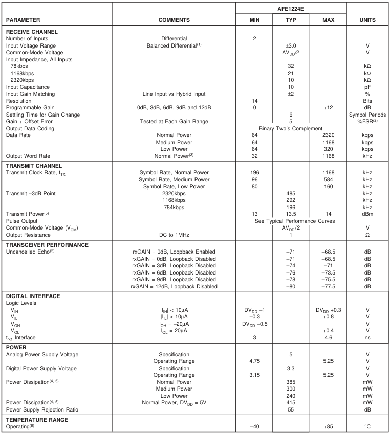
NOTES: (1) With a balanced differential signal, the positive input is 180° out-of-phase with the negative input, therefore the actual voltage swing about the commonmode voltage on each pin is ±1.5V to achieve a total input range of ±3.0V or 6Vp-p. (2) FSR is Full-Scale Range. (3) The output data is available at twice the symbol rate with interpolated values. (4) With a pseudo-random equiprobable sequence of HDSL pulses; 13.5dBm applied to the transformer (16.5dBm output from txLINE+ and txLINE–). (5) See the Discussion of Specifications section of this data sheet for more information. (6) Functionality only guaranteed over temperature range.
The information provided herein is believed to be reliable; however, BURR-BROWN assumes no responsibility for inaccuracies or omissions. BURR-BROWN assumes no responsibility for the use of this information, and all use of such information shall be entirely at the user’s own risk. Prices and specifications are subject to change without notice. No patent rights or licenses to any of the circuits described herein are implied or granted to any third party. BURR-BROWN does not authorize or warrant any BURR-BROWN product for use in life support devices and/or systems.
Page 3
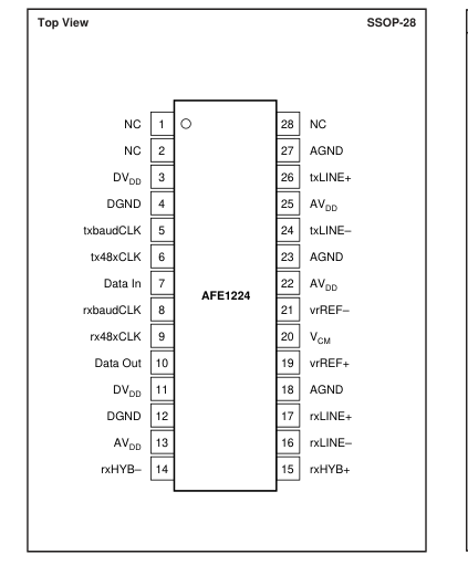
PIN CONFIGURATION
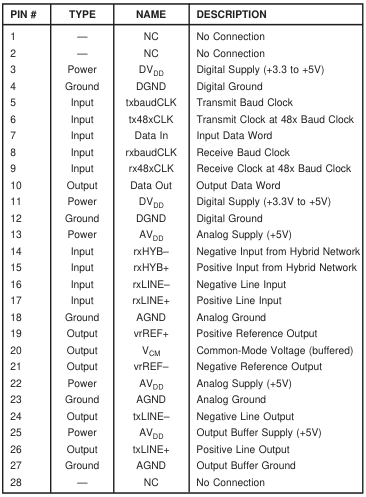
PIN DESCRIPTIONS
ELECTROSTATIC
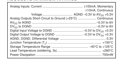
ABSOLUTE MAXIMUM RATINGS
DISCHARGE SENSITIVITY
This integrated circuit can be damaged by ESD. Burr-Brown
recommends that all integrated circuits be handled with
appropriate precautions. Failure to observe proper handling
and installation procedures can cause damage. ESD damage can range from subtle performance degradation
to complete device failure. Precision integrated circuits may
be more susceptible to damage because very small parametric
changes could cause the device not to meet its published
specifications.
PACKAGE/ORDERING INFORMATION
| PRODUCT | PACKAGE | PACKAGE DRAWING NUMBER(1) | SPECIFIED TEMPERATURE RANGE | PACKAGE MARKING | ORDERING NUMBER(2) | TRANSPORT MEDIA |
| AFE1224E " | SSOP-28 " | 324 " | –40°C to +85°C " | AFE1224E " | AFE1224E AFE1224E/1K | Rails Tape and Reel |
NOTES: (1) For detailed drawing and dimension table, please see end of data sheet, or Appendix C of Burr-Brown IC Data Book. (2) Models with a slash (/) are available only in Tape and Reel in the quantities indicated (e.g., /1K indicates 1000 devices per reel). Ordering 1000 pieces of “AFE1224E/1K” will get a single 1000- piece Tape and Reel. For detailed Tape and Reel mechanical information, refer to Appendix B of Burr-Brown IC Data Book.
Page 4
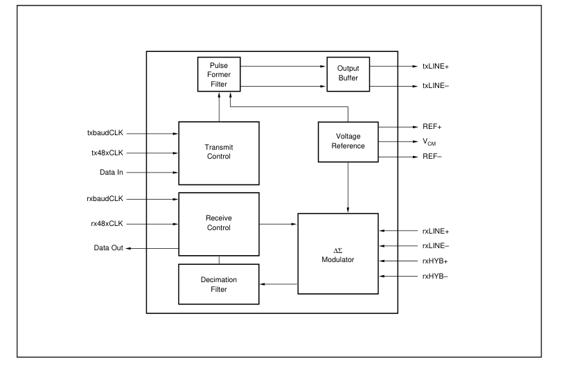
BLOCK DIAGRAM
Page 5
TYPICAL PERFORMANCE CURVES
At Output of HDSL Pulse Transformer
The curves shown below are measured at the line output of the HDSL transformer. Typical at 25°C, AVDD+ = +5V, DVDD+ = +3.3V, and fTX = 1168kHz, unless otherwise specified.
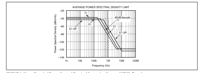
CURVE 1. Upper Bound of Power Spectral Density Measured at Output of HDSL Transformer.
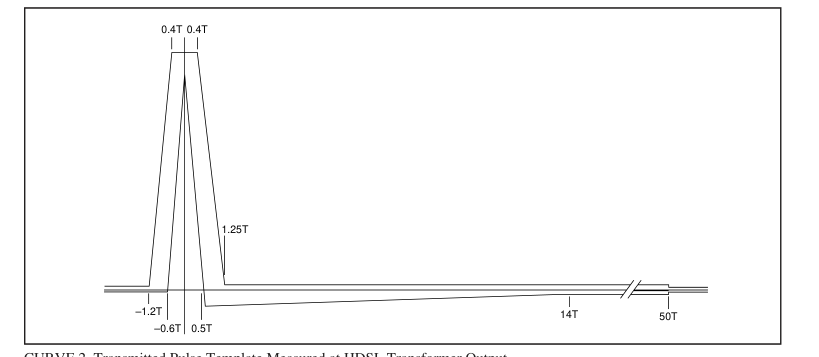
CURVE 2. Transmitted Pulse Template Measured at HDSL Transformer Output.
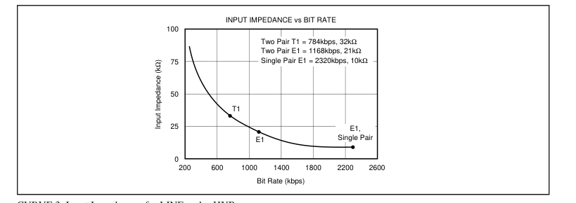
CURVE 3. Input Impedance of rxLINE and rxHYB.
Page 6
THEORY OF OPERATION
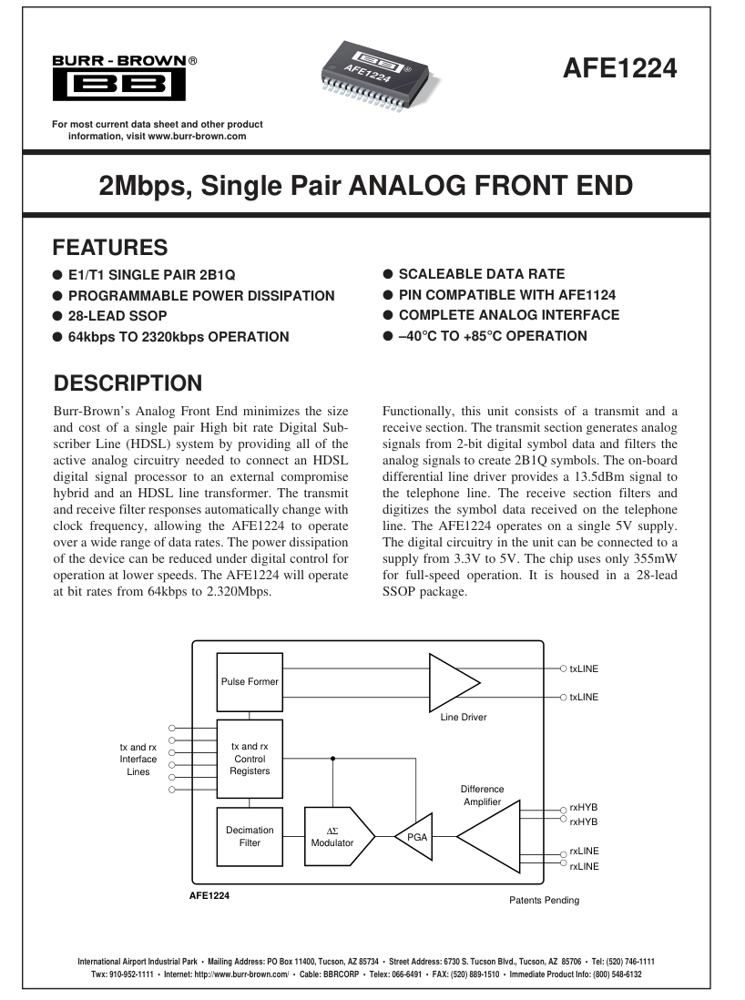
The AFE1224 consists of a transmit and a receive channel. It interfaces to the HDSL DSP through a six wire serial interface, three wires for the transmit channel and three wires for the receive channel. It interfaces to the HDSL telephone line transformer and external compromise hybrid through transmit and receive analog connections. The transmit channel consists of a digital-to-analog converter and a switched-capacitor pulse forming network followed by a differential line driver. The pulse forming network receives 2-bit digital symbol data and generates a filtered 2B1Q analog output waveform. The differential line driver uses a composite output stage combining class B
operation (for high efficiency driving large signals) with class AB operation (to minimize crossover distortion). The receive channel is designed around a fourth-order delta sigma A/D converter. It includes a difference amplifier designed to be used with an external compromise hybrid for first order analog echo cancellation. A programmable gain amplifier with gains of 0dB to +12dB is also included. The delta-sigma modulator operating at a 24x oversampling ratio produces a 14-bit output at rates up to 584kHz (1.168Mbps). The receive channel operates by summing the two differential inputs, one from the line (rxLINE) and the other from the
compromise hybrid (rxHYB). The connection of these two inputs so that the hybrid signal is subtracted from the line signal is described in the paragraph titled “Echo Cancellation in the AFE.” The equivalent gain for each input in the difference amp is one. The resulting signal then passes to a programmable gain amplifier which can be set for gains of 0dB through +12dB. Following the PGA, the ADC converts the signal to a 14-bit digital word. The serial interface consists of three wires for transmit and three wires for receive. The three-wire transmit interface is transmit baud rate clock, transmit 48x oversampling clock and Data Out. The three-wire receive interface is receive
baud rate clock, receive 48x oversampling clock and Data In. The transmit and receive clocks are supplied to the AFE1224 from the DSP and are completely independent.
DIGITAL DATA INTERFACE
Data is received by the AFE1224 from the DSP on the Data In line. Data is transmitted from the AFE1224 to the DSP on the Data Out line. The paragraphs below describe the timing of these signals and data structure. Data is transmitted and received in synchronization with the 48x transmit and receive clocks (tx48xCLK and rx48xCLK). There are 48-bit times in each baud period. Data In is
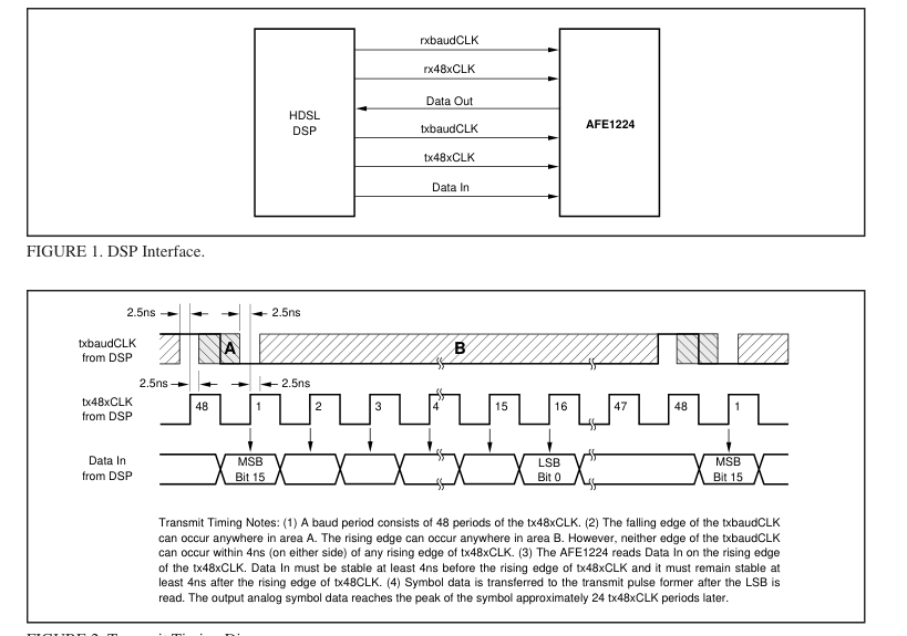
FIGURE 2. Transmit Timing Diagram.
Page 7
received in the first 16 bits of each baud period. The remaining 32-bit periods are not used for Data In. Data Out is transmitted during the first 16 bits of the baud period. A second interpolated value is transmitted in subsequent bits of the baud period. txbaudCLK: The transmit data baud rate, generated by the DSP. It is 784kHz for T1 or 1168kHz for E1. It may vary from 32kHz (64kbps) to 1168Hz (2.320Mbps). tx48xCLK: The transmit pulse former oversampling sampling clock, generated by the DSP. It is 48x the transmit symbol rate or 56.064MHz for 1168kHz symbol rate. This clock should run continuously. Data In: This is a 16-bit output data word sent from the DSP
to the AFE. The sixteen bits include tx symbol information and other control bits, as described below. The data should be clocked out of the DSP on the falling edge and should be
valid on the rising edge of the tx48xCLK. The AFE1224 reads Data In on the rising edge of the tx48xCLK. The bits are defined in Table I. Data In is read by the AFE1224 during the first 16 bits periods of each baud period. Only the first 8 bits are used in the AFE1224. The second 8 bits are reserved for use in the future products. The remaining 32 bits periods of the baud period are not used for Data In. Data In Bits tx enable signal—This bit controls the tx Symbol definition bits. If this bit is 0, only a 0 symbol is transmitted regardless of the state of the tx Symbol definition bits. If this bit is 1, the tx Symbol definition bits determine the output symbol.
tx Symbol Definition—These two bits determine the output 2B1Q symbol transmitted. Rx Gain Settings—These bits set the gain of the receive channel programmable gain amplifier.
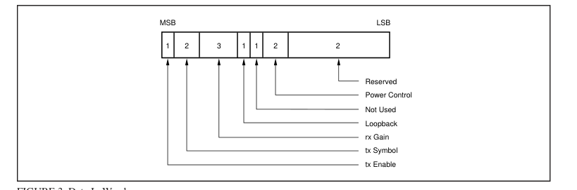
FIGURE 3. Data In Word.
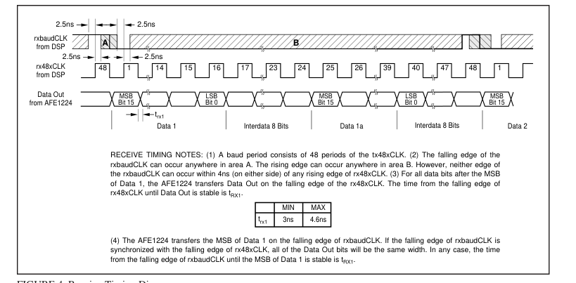
FIGURE 4. Receive Timing Diagram.
Page 8
Loopback Control—This bit controls the operation of loopback. When enabled (logic 1), the rxLINE+ and rxline– inputs are disconnected from the AFE. The rxHYB+ and rxHYB– inputs remain connected. When disabled, the rxLINE+ and rxLINE– inputs are connected. Power Control—These bits control the power dissipation and the maximum speed of the AFE1224.
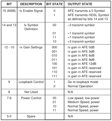
TABLE I. Data Input Format.
rxbaudCLK: This is the receive data baud rate (symbol clock), generated by the DSP. It is 392kHz for T1 or 584kHz for E1. It can vary from 32kHz (64kbps) to 584kHz (1.168Mbps). rx48xCLK: This is the A/D converter over-sampling clock, generated by the DSP. It is 48x the receive symbol rate or 28.032MHz for 584kHz symbol rate. This clock should run continuously. Data Out: This is the 14-bit A/D converter output data (+ 2 spare bits) sent from the AFE to the DSP. The 14 bits from the A/D Converter will be the upper bits of the 16-bit word (bits 15-2). The spare bits (1 and 0) will be always be LOW. Eight additional bits follow which are always HIGH. The data is clocked out on the falling edge and valid at the rising
edge of the rx48xCLK. The bandwidth of the A/D converter dicimation filter is equal to one-half of the symbol rate. The nominal output rate of the A/D converter is one conversion per symbol period. For more flexible post-processing, there is a second true A/D conversion available in each symbol period. In Figure 4, the first conversion is shown as Data 1 and the second conversion is shown as Data 1a. It is recommended that rxbaudCLK be used with the rx48xCLK to read Data 1 while Data 1a is ignored. However, either data output may be used and both outputs may be used for more flexible post-processing.
DATA OUT PER SYMBOL PERIOD
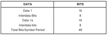
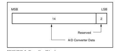
FIGURE 5. Data Out Word.
ANALOG-TO-DIGITAL CONVERTER DATA
The A/D converter data from the receive channel is coded in Binary Two’s Complement.
| ANALOG INPUT | A/D CONVERTER DATA |
| Positive Full Scale Mid Scale Negative Full Scale | MSB LSB 01111111111111 00000000000000 10000000000000 |
TABLE II. Data Output Format.
ECHO CANCELLATION IN THE AFE
The rxHYB input is subtracted from the rxLINE input for first order echo cancellation. For correct operation, be certain that the rxLINE input is connected to the same polarity signal at the transformer (+ to + and – to –) while the rxHYB input is connected to opposite polarity through the compromise hybrid (– to + and + to –). Refer to the basic connection diagram in Figure 6.
SCALEABLE TIMING
The AFE1224 scales operation with the clock frequency. All internal filters and the pulse former change frequency with the clock speed so that the unit can be used at different frequencies just by changing the clock speed. For the receive channel, the digital filtering of the deltasigma converter scales directly with the clock speed. The bandwidth of the converter’s decimation filter is always onehalf of the symbol rate. The only receive channel issue in changing baud rate is the passive single pole anti-alias filter (see the following section). For systems implementing a broad range of speeds, selectable cut-off frequencies for the passive anti-alias filter should be used.
Page 9
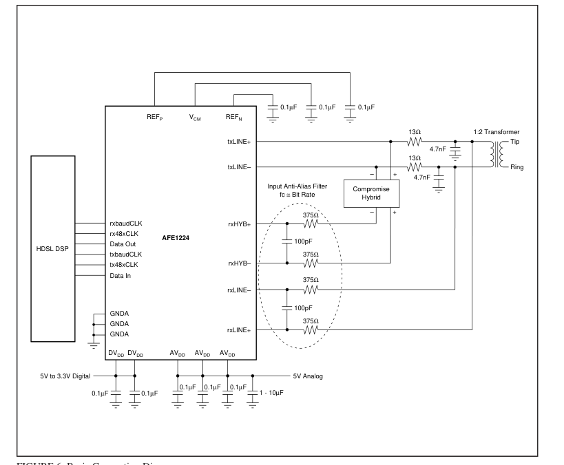
FIGURE 6. Basic Connection Diagram.
For the transmit channel, the pulse shape and the power spectral density scale directly with the clock rate. The power spectral density shown in Curve 1 and the pulse template shown in Curve 2 are measured at the output of the transformer. The transformer and the RC circuit on the output provide some smoothing for the output transmission. At lower bit rates, the amount of smoothing will be less and more output filtering may be needed.
rxHYB AND rxLINE INPUT ANTI-ALIASING FILTERS An external input anti-aliasing filter is needed on the hybrid and line inputs as shown in the basic connection diagram (Figure 6). The –3dB frequency of the input anti-aliasing
filter for the rxLINE and rxHYB differential inputs should be approximately 2MHz for single pair T1 and E1 symbol rates. Suggested values for the filter are 375Ω for each of the two input resistors and 100pF for the capacitor. Together the two 375Ω resistors and the 100pF capacitor result in a 3dB frequency of just over 2MHz. The 375Ω input resistors will result in minimal voltage divider loss with the input impedance of the AFE1224. This circuit applies at rates of 1Mbps to 2Mbps. For slower rates, the anti-aliasing filters will give best performance with 3dB frequency approximately equal to the bit rate. For instance, a 3dB frequency of 320kHz may be used for a single line bit rate of 320k bits per second.
Page 10
DISCUSSION OF
SPECIFICATIONS
UNCANCELLED ECHO
A key measure of transceiver performance is uncancelled echo. Uncancelled echo is the summation of all of the errors in the transmit and receive paths of the AFE1224. It includes effects of linearity, distortion and noise. Uncancelled echo is tested in production by Burr-Brown with a circuit that is similar to the one shown in Figure 7, Uncancelled Echo Test Diagram. The measurement of uncancelled echo is made as follows: The AFE is connected to an output circuit including a typical 1:2 line transformer. The line is simulated by a 135Ω resistor. Symbol sequences are generated by the tester and applied both to the AFE and to the input of an adaptive filter.
The output of the adaptive filter is subtracted from the AFE output to form the uncancelled echo signal. Once the filter taps have converged, the rms value of the uncancelled echo is calculated. Since there is no far-end signal source or additive line noise, the uncancelled echo contains only noise and linearity errors generated in the transmit and receive sections of the AFE1224. The data sheet value for uncancelled echo is the ratio of the rms uncancelled echo (referred to the receiver input through the receiver gain) to the nominal transmitted signal (13.5dBm into 135Ω, or 1.74Vrms). This echo value is measured under a variety of conditions: with loopback
enabled (line input disconnected); with loopback disabled under all receiver gain ranges; and with the line shorted (S1 closed, see Figure 7).
POWER DISSIPATION
The power dissipation of the AFE1224 is digitally programmable by the user to three levels: normal, medium and low. The maximum bit rate of the AFE1205 is 2.3Mbps with normal power dissipation. At lower power dissipation levels, the maximum bit rate is lower. The power dissipation listed in the Specifications Table applies under these normal operating conditions: 5V analog power supply, 3.3V digital power supply, standard 13.5dBm delivered to the line, and a pseudo-random equiprobable sequence of HDSL output pulses. The power dissipation specifications includes all power dissipated in the AFE1224, but it does not include power dissipated in the external load.
The external power is 16.5dBm: 13.5dBm to the line and 13.5dBm to the impedance matching resistors. The external load power of 16.5dBm is 45mW. The typical power dissipation in the AFE1224 under various conditions is shown in Table III.
| POWER LEVEL | MAXIMUM SPEED | MINIMUM SPEED | TYPICAL POWER DISSIPATION |
|---|---|---|---|
| Normal Medium Low | 2.3Mbps 1.168Mbps 320kbps | 64kbps 64kbps 64kbps | 385mW 300mW 240mW |
TABLE III. Typical Power Dissipation.
LAYOUT
The analog front end of an HDSL system has two conflicting requirements. It must accept and deliver moderately high rate digital signals and it must generate, drive, and convert precision analog signals. To achieve optimal system performance with the AFE1224, both the digital and the analog sections must be treated carefully in board layout design. The power supply for the digital section of the AFE1224 can range from 3.3V to 5V. This supply should be decoupled to digital ground with ceramic 0.1µF capacitors placed as close to DGND and DVDD as possible. One capacitor should be placed between pins 3 and 4 and the second capacitor between pins 11 and 12. Ideally, both a digital power supply
plane and a digital ground plane should run up to and underneath the digital pins of the AFE1224 (pins 5 through 10). However, DVDD may be supplied by a wide printed circuit board (PCB) trace. A digital ground plane underneath all digital pins is strongly recommended. The remaining portion of the AFE1224 should be considered analog. All AGND pins should be connected directly to a common analog ground plane and all AVDD pins should be connected to an analog 5V power plane. Both of these planes should have a low impedance path to the power supply. The analog power supply pins should be decoupled to analog ground with ceramic 0.1µF capacitors placed as close to the
AFE1224 as possible. One 10µF tantalum capacitor should also be used with each AFE1224 between the analog supply and analog ground. Ideally, all ground planes and traces and all power planes and traces should return to the power supply connector before being connected together (if necessary). Each ground and power pair should be routed over each other, should not overlap any portion of another pair, and the pairs should be separated by a distance of at least 0.25 inch (6mm). One exception is that the digital and analog ground planes should be connected together underneath the AFE1224 by a small trace.
Page 11
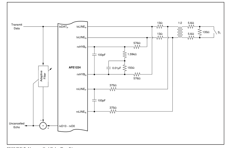
FIGURE 7. Uncancelled Echo Test Diagram.
Page 12
PACKAGE OPTION ADDENDUM
14-Oct-2008
www.ti.com
PACKAGING INFORMATION

(1) The marketing status values are defined as follows: ACTIVE: Product device recommended for new designs. LIFEBUY: TI has announced that the device will be discontinued, and a lifetime-buy period is in effect. NRND: Not recommended for new designs. Device is in production to support existing customers, but TI does not recommend using this part in a new design. PREVIEW: Device has been announced but is not in production. Samples may or may not be available. OBSOLETE: TI has discontinued the production of the device.
(2) Eco Plan - The planned eco-friendly classification: Pb-Free (RoHS), Pb-Free (RoHS Exempt), or Green (RoHS & no Sb/Br) - please check http://www.ti.com/productcontent for the latest availability information and additional product content details. TBD: The Pb-Free/Green conversion plan has not been defined. Pb-Free (RoHS): TI's terms "Lead-Free" or "Pb-Free" mean semiconductor products that are compatible with the current RoHS requirements for all 6 substances, including the requirement that lead not exceed 0.1% by weight in homogeneous materials. Where designed to be soldered at high temperatures, TI Pb-Free products are suitable for use in specified lead-free processes.
Pb-Free (RoHS Exempt): This component has a RoHS exemption for either 1) lead-based flip-chip solder bumps used between the die and package, or 2) lead-based die adhesive used between the die and leadframe. The component is otherwise considered Pb-Free (RoHS compatible) as defined above. Green (RoHS & no Sb/Br): TI defines "Green" to mean Pb-Free (RoHS compatible), and free of Bromine (Br) and Antimony (Sb) based flame retardants (Br or Sb do not exceed 0.1% by weight in homogeneous material)
(3) MSL, Peak Temp. -- The Moisture Sensitivity Level rating according to the JEDEC industry standard classifications, and peak solder temperature.
Important Information and Disclaimer:The information provided on this page represents TI's knowledge and belief as of the date that it is provided. TI bases its knowledge and belief on information provided by third parties, and makes no representation or warranty as to the accuracy of such information. Efforts are underway to better integrate information from third parties. TI has taken and continues to take reasonable steps to provide representative and accurate information but may not have conducted destructive testing or chemical analysis on incoming materials and chemicals. TI and TI suppliers consider certain information to be proprietary, and thus CAS numbers and other limited
information may not be available for release.
In no event shall TI's liability arising out of such information exceed the total purchase price of the TI part(s) at issue in this document sold by TI to Customer on an annual basis.
Addendum-Page 1
Page 13
IMPORTANT NOTICE
Texas Instruments Incorporated and its subsidiaries (TI) reserve the right to make corrections, modifications, enhancements, improvements, and other changes to its products and services at any time and to discontinue any product or service without notice. Customers should obtain the latest relevant information before placing orders and should verify that such information is current and complete. All products are sold subject to TI’s terms and conditions of sale supplied at the time of order acknowledgment. TI warrants performance of its hardware products to the specifications applicable at the time of sale in accordance with TI’s standard warranty. Testing and other quality control techniques are used to the extent TI deems necessary to support this warranty. Except where
mandated by government requirements, testing of all parameters of each product is not necessarily performed. TI assumes no liability for applications assistance or customer product design. Customers are responsible for their products and applications using TI components. To minimize the risks associated with customer products and applications, customers should provide adequate design and operating safeguards. TI does not warrant or represent that any license, either express or implied, is granted under any TI patent right, copyright, mask work right, or other TI intellectual property right relating to any combination, machine, or process in which TI products or services are used. Information
published by TI regarding third-party products or services does not constitute a license from TI to use such products or services or a warranty or endorsement thereof. Use of such information may require a license from a third party under the patents or other intellectual property of the third party, or a license from TI under the patents or other intellectual property of TI. Reproduction of TI information in TI data books or data sheets is permissible only if reproduction is without alteration and is accompanied by all associated warranties, conditions, limitations, and notices. Reproduction of this information with alteration is an unfair and deceptive
business practice. TI is not responsible or liable for such altered documentation. Information of third parties may be subject to additional restrictions. Resale of TI products or services with statements different from or beyond the parameters stated by TI for that product or service voids all express and any implied warranties for the associated TI product or service and is an unfair and deceptive business practice. TI is not responsible or liable for any such statements. TI products are not authorized for use in safety-critical applications (such as life support) where a failure of the TI product would reasonably be expected to cause severe personal injury or death, unless officers of the parties have executed an agreement specifically governing
such use. Buyers represent that they have all necessary expertise in the safety and regulatory ramifications of their applications, and acknowledge and agree that they are solely responsible for all legal, regulatory and safety-related requirements concerning their products and any use of TI products in such safety-critical applications, notwithstanding any applications-related information or support that may be provided by TI. Further, Buyers must fully indemnify TI and its representatives against any damages arising out of the use of TI products in such safety-critical applications. TI products are neither designed nor intended for use in military/aerospace applications or environments unless the TI products are
specifically designated by TI as military-grade or "enhanced plastic." Only products designated by TI as military-grade meet military specifications. Buyers acknowledge and agree that any such use of TI products which TI has not designated as military-grade is solely at the Buyer's risk, and that they are solely responsible for compliance with all legal and regulatory requirements in connection with such use. TI products are neither designed nor intended for use in automotive applications or environments unless the specific TI products are designated by TI as compliant with ISO/TS 16949 requirements. Buyers acknowledge and agree that, if they use any non-designated
products in automotive applications, TI will not be responsible for any failure to meet such requirements. Following are URLs where you can obtain information on other Texas Instruments products and application solutions: Products Amplifiers
amplifier.ti.com
Audio
Data Converters
dataconverter.ti.com
Automotive
DSP
dsp.ti.com
Broadband
Clocks and Timers
www.ti.com/clocks
Interface
interface.ti.com
Medical
Logic
logic.ti.com
Military
Power Mgmt
power.ti.com
Microcontrollers
microcontroller.ti.com
Security
RFID
www.ti-rfid.com
Telephony
RF/IF and ZigBee® Solutions www.ti.com/lprf
Wireless
Applications
www.ti.com/audio www.ti.com/automotive www.ti.com/broadband
Digital Control
www.ti.com/digitalcontrol www.ti.com/medical www.ti.com/military
Optical Networking
www.ti.com/opticalnetwork www.ti.com/security www.ti.com/telephony
Video & Imaging
www.ti.com/video www.ti.com/wireless
Mailing Address: Texas Instruments, Post Office Box 655303, Dallas, Texas 75265
Copyright © 2008, Texas Instruments Incorporated