


 Download PDF
2Mbps, Single Pair HDSL Analog Front End datasheet
Document overview
- PDF pages: 15
Technical content
Page 1
2Mbps, Single Pair HDSL ANALOG FRONT END
FEATURES
G E1/T1 SINGLE PAIR 2B1Q OPERATION G COMPLETE ANALOG INTERFACE G 385mW POWER DISSIPATION G PROGRAMMABLE POWER
DESCRIPTION
Burr-Brown’s Analog Front End greatly reduces the size and cost of a single pair HDSL (High bit rate Digital Subscriber Line) system by providing all of the active analog circuitry needed to connect an HDSL digital signal processor to an external compromise hybrid and an HDSL line transformer. The transmit and receive filter responses automatically change with clock frequency, allowing the AFE1203 to operate over a wide range of data rates. The power dissipation of the device can be reduced under digital control for operation at lower speeds. The AFE1203 will operate at bit rates from 160kbps to 2.3Mbps. It meets ETSI PSD specifications for single pair E1,
as well as ETSI and ANSI PSD specifications for two pair E1 and T1. Functionally, this unit consists of a transmit and a receive section. The transmit section generates, filters, and buffers outgoing 2B1Q data. The receive section filters and digitizes the symbol data received on the telephone line. This IC operates
D/A Converter
PLLOUT PLLIN
Transmit Control
txDAT txCLK
rxSYNC
Receive
rxLOOP
Control 2 rxGAIN
14 Decimation
rxD13 - rxD0
Filter
G 48-LEAD SSOP PACKAGE G SCALEABLE DATA RATE G OPERATION FROM 2.3Mbps TO 160kbps G +5V ONLY (5V OR 3.3V DIGITAL)
G –40°C TO +85°C OPERATION
on a single 5V supply. The digital circuitry in the unit can be connected to a supply from 3.3V to 5V. The chip uses only 385mW for full-speed operation. It is housed in a small 48-lead SSOP package. The receive channel is designed around a fourth-order deltasigma analog-to-digital converter. It includes a difference am- plifier designed to be used with an external compromise hybrid for first-order analog echo cancellation. A programmable gain amplifier with gains 0dB to +9dB is also included. The deltasigma modulator, operating at a 24X oversampling ratio, produces a 14-bit output at symbol rates up to 1168kHz (for 2.3Mbps operation). The transmit channel consists of a digital-to-analog converter and
switched-capacitor pulse forming network followed by a differential line driver. The pulse forming network receives symbol data and generates a standard 2B1Q output waveform. The differential line driver uses a composite output stage combining class B operation (for high efficiency driving large signals) with class AB operation (to minimize crossover distortion).
txLINEP
Pulse
Line
Former
Driver
txLINEN
REFP
Voltage
VCM
Reference
REFN
rxLINEP rxLINEN
Delta-Sigma Modulator
rxHYBP rxHYBN
Patents Pending
International Airport Industrial Park • Mailing Address: PO Box 11400, Tucson, AZ 85734 • Street Address: 6730 S. Tucson Blvd., Tucson, AZ 85706 • Tel: (520) 746-1111 • Twx: 910-952-1111 Internet: http://www.burr-brown.com/ • FAXLine: (800) 548-6133 (US/Canada Only) • Cable: BBRCORP • Telex: 066-6491 • FAX: (520) 889-1510 • Immediate Product Info: (800) 548-6132
©1998 Burr-Brown Corporation
PDS-1460A
Printed in U.S.A. October, 1998
SBWS007
Page 2
SPECIFICATIONS
Typical at 25°C, AVDD = +5V, DVDD = +3.3V, ftx = 1168kHz (E1 single pair rate) and Normal Power mode, unless otherwise specified.
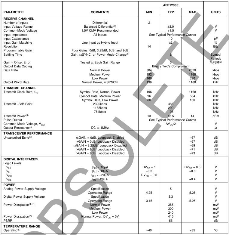
NOTES: (1) With a balanced differential signal, the positive input is 180° out of phase with the negative input, therefore the actual voltage swing about the common mode voltage on each pin is ±1.5V to achieve a differential input range of ±3.0V or 6Vp-p. (2) FSR is Full-Scale Range. (3) The output data is available at twice the symbol rate with interpolated values. (4) With a pseudo-random equiprobable sequence of HDSL pulses; 13.5dBm applied to the transformer (27dBm output from txLINEP and txLINEN). (5) Guaranteed by design and characterization. (6) Uncancelled Echo is a measure of the total analog errors in the transmitter and receiver sections including the effect of non-linearity and noise. See the Discussion of Specifications section of this data sheet for more information. (7) Power dissipation
includes only the power dissipated within the component and does not include power dissipated in the external loads. The AFE1203 is tested with a 1:2 line transformer. (8) This is the settling time required for any gain change, change of rxSYNC or any change of power mode.
Page 3
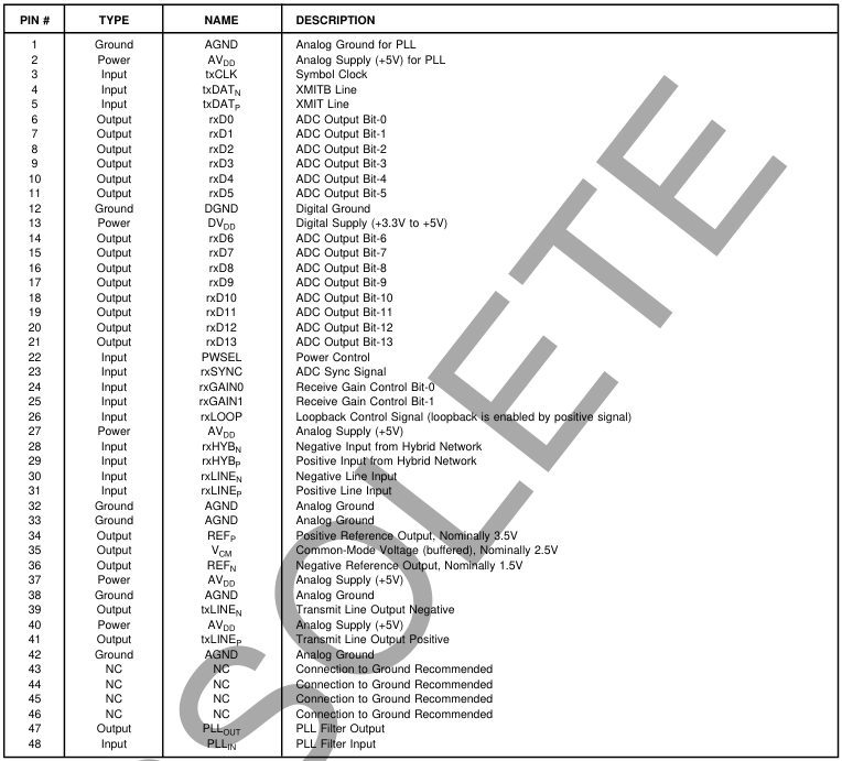
PIN DESCRIPTIONS
The information provided herein is believed to be reliable; however, BURR-BROWN assumes no responsibility for inaccuracies or omissions. BURR-BROWN assumes no responsibility for the use of this information, and all use of such information shall be entirely at the user’s own risk. Prices and specifications are subject to change without notice. No patent rights or licenses to any of the circuits described herein are implied or granted to any third party. BURR-BROWN does not authorize or warrant any BURR-BROWN product for use in life support devices and/or systems.
Page 4
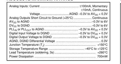
ABSOLUTE MAXIMUM RATINGS
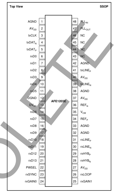
PIN CONFIGURATION
PACKAGE/ORDERING INFORMATION
| PRODUCT | PACKAGE | PACKAGE DRAWING NUMBER(1) | TEMPERATURE RANGE |
| AFE1203E | 48-Lead SSOP | 333 | –40°C to +85°C |
NOTE: (1) For detailed drawing and dimension table, please see end of data sheet, or Appendix C of Burr-Brown IC Data Book.
ELECTROSTATIC
DISCHARGE SENSITIVITY
This integrated circuit can be damaged by ESD. Burr-Brown
recommends that all integrated circuits be handled with
appropriate precautions. Failure to observe proper handling
and installation procedures can cause damage. ESD damage can range from subtle performance degradation
to complete device failure. Precision integrated circuits may
be more susceptible to damage because very small parametric
changes could cause the device not to meet its published
specifications.
Page 5
TYPICAL PERFORMANCE CURVES
At Output of Pulse Transformer
Typical at 25°C, AVDD = +5V, and DVDD = +3.3V, unless otherwise specified.
AVERAGE POWER SPECTRAL DENSITY LIMIT
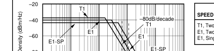
| SPEED | LOWER LIMIT | BREAK FREQUENCY | SLOPE | UPPER LIMIT |
| T1, Two Pair E1, Two Pair E1, Single Pair (E1-SP) | –38dBm/Hz –40dBm/Hz –42.5dBm/Hz | 196kHz 292kHz 485kHz | E –80dB/decade –80dB/decade –80dB/decade | –118dBm/Hz –120dBm/Hz –122dBm/Hz |
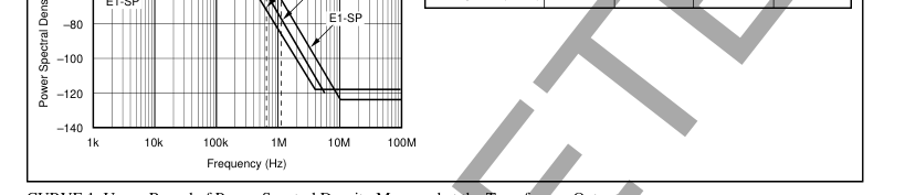
CURVE 1. Upper Bound of Power Spectral Density Measured at the Transformer Output.
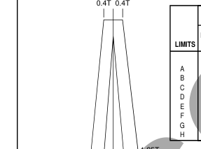
| LIMITS | TWO PAIR T1 AND E1 | SINGLE PAIR E1 | ||||||||
| NORMALIZED LEVELS | L QUATENARY SYMBOLS (V) | NORMALIZED LEVELS | QUATENARY SYMBOLS (V) | |||||||
| A B C D E F G H | O 0.01 1.07 1.00 0.93 0.03 –0.01 –0.16 –0.05 | +3 0.0264 2.8248 2.6400 2.4552 0.0792 0.0264 –0.4224 –0.1320 | +1 0.0088 0.9416 0.8800 0.8184 0.0264 –0.0088 –0.1408 –0.0440 | –1 –0.0088 –0.9416 –0.8800 –0.8184 –0.0264 0.0088 0.1408 0.0440 | –3 –0.0264 –2.8248 –2.6400 –2.4552 –0.0792 0.0264 0.4224 0.1320 | 0.01 1.07 1.00 0.93 0.04 –0.01 –0.20 –0.05 | +3 0.0250 2.6750 2.5000 2.3250 0.1000 –0.0250 –0.5000 –1.2500 | +1 0.0083 0.8917 0.8333 0.7750 0.0333 –0.0083 –0.1667 –0.0417 | –1 –0.0083 –0.8917 –0.8333 –0.7750 –0.0333 0.0083 0.1667 0.0417 | –3 0.0250 –2.6750 –2.5000 –2.3250 –0.1000 0.0250 0.5000 0.1250 |

CURVE 2. Transmitted Pulse Template and Actual Performance as Measured at the Transformer Output.
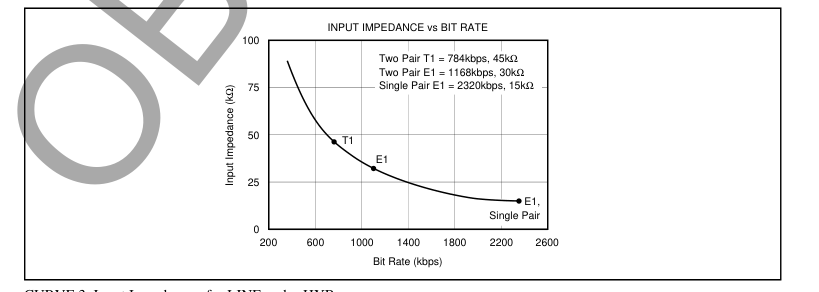
CURVE 3. Input Impedance of rxLINE and rxHYB.
Page 6
THEORY OF OPERATION
The transmit channel consists of a D/A converter and a switched-capacitor pulse forming network followed by a differential line driver. The pulse forming network receives symbol data from the DSP and generates a 2B1Q output waveform. The output meets the pulse mask and power spectral density requirements defined in European Telecommunications Standards Institute document RTR/TM-03036 for E1 mode and in sections 6.2.1 and 6.2.2.1 of Bellcore technical advisory TA-NWT-001210 for T1 mode. The differential line driver uses a composite output stage combining class B operation (for high efficiency driving large signals) with class AB operation (to minimize crossover
distortion). The receive channel is designed around a fourth-order delta sigma A/D converter. It includes a difference amplifier designed to be used with an external compromise hybrid for first-order analog crosstalk reduction. A programmable gain amplifier with gains of 0dB to +9dB is also included. The delta sigma modulator operating at a 24X oversampling ratio produces 14 bits of resolution at output rates up to 584kHz. The basic functionality of the AFE1203 is illustrated in Figure 1. The receive channel operates by summing the two differential inputs, one from the line (rxLINE) and the other from the compromise hybrid (rxHYB). The connection of these two
inputs so that the hybrid signal is subtracted from the line signal is described in the paragraph titled “Echo Cancellation in the AFE”. The equivalent gain for each input in the difference amp is 1. The resulting signal then passes to a programmable gain amplifier which can be set for gains of 0dB through 9dB. The ADC converts the signal to a 14-bit digital word, rxD13-rxD0.
SCALEABLE TIMING
The AFE1203 scales operation with the clock frequency. All internal filters, the A/D converter, the D/A converter, and the pulse former change frequency with the clock speed so that the unit can be used at different frequencies by changing the clock speed.
rxLOOP INPUT rxLOOP is the loopback control signal. When enabled, the rxLINEP and rxLINEN inputs are disconnected from the AFE. The rxHYBP and rxHYBN inputs remain connected. Loopback is enabled by applying a positive signal (Logic 1) to rxLOOP.
ECHO CANCELLATION IN THE AFE
The rxHYB input is designed to be subtracted from the rxLINE input for first-order echo cancellation. To accomplish this, note that the rxLINE input is connected to the same polarity signal at the transformer (positive to positive and negative to negative) while the rxHYB input is connected to opposite polarity through the compromise hybrid (negative to positive and positive to negative) as shown in Figure 2.
RECEIVE DATA CODING
The data from the receive channel A/D converter is coded in Straight Offset Binary.

RECEIVE CHANNEL PROGRAMMABLE
GAIN AMPLIFIER
The gain of the amplifier at the input of the Receive Channel is set by two gain control pins, rxGAIN1 and rxGAIN0. The resulting gain between 0dB and +9dB is shown below.
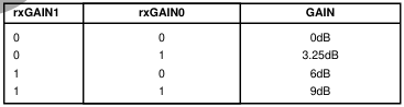
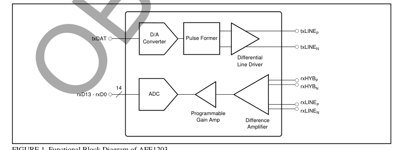
FIGURE 1. Functional Block Diagram of AFE1203.
Page 7
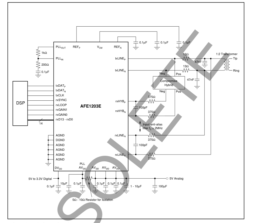
FIGURE 2. Basic Connection Diagram.
rxHYB AND rxLINE INPUT ANTI-ALIASING FILTERS The –3dB frequency of the input anti-aliasing filter for the rxLINE and rxHYB differential inputs should be approximately 2MHz for operation at 2.3Mbps. Suggested values for the filter are 375Ω for each of the two input resistors and 100pF for the capacitor. Together the two 375Ω resistors and the 100pF capacitor result in –3dB frequency of just over 2MHz. The 375Ω input resistors will result in a minimal voltage divider loss with the input impedance of the AFE1203. This circuit applies at rates of 1Mbps to 2Mbps. For slower rates, the anti-aliasing filters will give best performance with their –3dB frequency approximately equal to the bit rate. For
example, a –3dB frequency of 500kHz should be used for a single pair bit rate of 500kbps.
rxHYB AND rxLINE INPUT BIAS VOLTAGE The transmitter output on the txLINE pins and the rxLINE inputs are centered at midscale, 2.5V. Inside the AFE1203, the rxHYB and rxLINE signals are subtracted as described in the paragraph on echo cancellation above. This means that the rxHYB inputs need to be centered at 2.5V just as the rxLINE signal is centered at 2.5V. The external compromise hybrid must be designed so that the signal into the rxHYB inputs remains centered at 2.5V.
Page 8
TIMING DIAGRAM
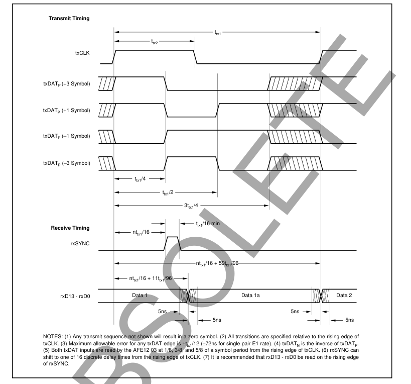
FIGURE 3. Timing Diagram.
RECEIVE TIMING
The rxSYNC signal controls portions of the A/D converter’s decimation filter and the data output timing of the A/D converter. It is generated at the symbol rate by the user and must be synchronized with txCLK. The leading edge of rxSYNC can occur at the leading edge of txCLK or it can be shifted by the user in increments of 1/16 of a symbol period to one of 15 discrete delay times after the leading edge of txCLK.
RECEIVE OUTPUT DATA RATE
The receive channel delta-sigma A/D converter of the AFE1203 uses a modulator which operates at an oversampling
rate of 24X the symbol rate. The A/D converter’s decimation filter downsamples the modulator output by a factor of 12. The bandwidth of the decimation filter is equal to one-half the symbol rate. This yields two output words per symbol period. These two output words are shown as Data 1 and Data 1a in Figure 3. The specifications of the AFE1203 assume that one A/D converter output is used per symbol period and the other output is ignored. The Receive Timing diagram above suggests using the rising edge of the rxSYNC pulse to read the first data output in a symbol period. Either data output may be used. Both data outputs may be used for more flexible post-processing.
Page 9
DISCUSSION OF
SPECIFICATIONS
UNCANCELLED ECHO
The key measure of transceiver performance is uncancelled echo. This measurement is made as shown in the diagram of Figure 4. The AFE is connected to an output circuit including a typical 1:2 line transformer. The line is simulated by a 135Ω resistor. Symbol sequences are generated by the tester and applied both to the AFE and to the input of an adaptive filter. The output of the adaptive filter is subtracted from the AFE output to form the uncancelled echo signal. Once the filter taps have converged, the rms value of the uncancelled echo is calculated. Since there is no far-end signal source or additive line noise, the uncancelled echo contains only noise
and linearity errors generated in the transmitter and receiver. The data sheet value for uncancelled echo is the ratio of the rms uncancelled echo (referred to the receiver input through the receiver gain) to the nominal transmitted signal (13.5dBm into 135Ω, or 1.74Vrms). This echo value is measured under a variety of conditions: with loopback enabled (line input disconnected); with loopback disabled under all receiver gain ranges; and with the line shorted (S1 closed in Figure 4).
PROGRAMMABLE POWER DISSIPATION
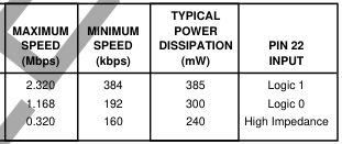
The power dissipation of the AFE1203 is digitally programmable by the user to three levels: Normal, Medium, and Low. The maximum bit rate of the AFE1203 is 2.3Mbps with Normal power dissipation. At lower power dissipation
levels, the maximum bit rate is lower and in addition, the minimum bit rate is lower. The power control pin (pin 22) has three input levels, Logic 1, Logic 0, and high impedance. In the high impedance state, up to 20µA leakage current can be tolerated out of the power control pin. The AFE1203 requires six baud periods to settle after a change in the power control pin status. Typical power dissipation specifications, shown in Table I, assume a 5V analog supply, a 3.3V digital supply, standard 13.5dBm delivered to the line, a pseudo random equiprobable sequence of HDSL output pulses, and a 1:2 turns ratio line transformer. The power dissipation specifications in-
cludes all power dissipated in the AFE1203—it does not include power dissipated in the external load. The external power is 16.5dBm, 13.5dBm to the line and 13.5dBm to the impedance matching resistors. The external power of 16.5dBm is 45mW. If a 5V digital supply is used rather than a 3.3V supply, the power dissipation increases by approximately 3mW.
POWER
LEVEL
Normal Medium Low
TABLE I. Power Control Operation.
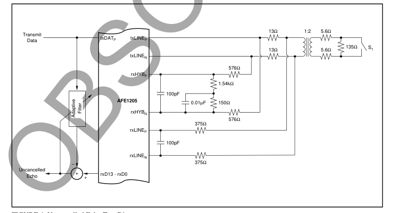
FIGURE 4. Uncancelled Echo Test Diagram.
Page 10
LAYOUT
The analog front end of an HDSL system has a number of conflicting requirements. It must accept and deliver digital outputs at fairly high rates of speed, phase-lock to a highspeed digital clock, and convert the line input to a highprecision (14-bit) digital output. Thus, there are really three sections of the AFE1203: the digital section, the phaselocked loop, and the analog section. A combined analog and digital ground plane is recommended. The ground plane should pass under all of the AFE1203 and its pins. The power supply for the digital section of the AFE1203 can range from 3.3V to 5V. This supply should be decoupled to ground with a ceramic 0.1µF capacitor placed as close to
DGND (pin 12) and DVDD (pin 13) as possible. Ideally, both a digital power supply plane and a ground plane should run up to and underneath the digital pins of the AFE1203 (pins 3 through 26). However, DVDD may be supplied by a wide printed circuit board (PCB) trace. A ground plane underneath all digital pins is strongly recommended. The Phase Locked Loop (PLL) analog supply, pin 2, must be derived from AVDD, the general analog supply. The power supply to the PLL must be in the range of 4.75V to 5.25V. The PLL section of the AFE1203 should be decoupled with
both a 10µF tantalum capacitor and a 0.1µF ceramic capacitor. Both capacitors should be placed between pins 1 and 2. The ceramic capacitor should be placed as close to the AFE1203 as possible. The placement of the tantalum capacitor is not as critical, but should be close. A 5Ω to 10Ω resistor should be used to connect the PLL supply (pin 2) to the analog supply. This resistor, in combination with the 10µF tantalum capacitor, form a low pass filter to keep glitches that occur on the general analog supply, AVDD, from affecting the PLL supply. The PLL ground (pin 1) should connect directly to the ground plane. The ground plane should also extend underneath PLLOUT and PLLIN
(pins 47 and 48, respectively). The remaining portion of the AFE1203 should be considered analog. All AGND pins should be connected directly to the common ground plane and all AVDD pins should be connected to an analog 5V power plane. Both of these planes should have a low impedance path to the power supply. Ideally, all ground planes and traces and all power planes and traces should return to the power supply connector before being connected together (if necessary). Each ground and power trace pair should be routed over each other, should not overlap any portion of another pair, and the pairs should be separated by a distance of at least 0.25 inch (6mm).
Page 11
IMPORTANT NOTICE
Texas Instruments and its subsidiaries (TI) reserve the right to make changes to their products or to discontinue any product or service without notice, and advise customers to obtain the latest version of relevant information to verify, before placing orders, that information being relied on is current and complete. All products are sold subject to the terms and conditions of sale supplied at the time of order acknowledgment, including those pertaining to warranty, patent infringement, and limitation of liability.
TI warrants performance of its semiconductor products to the specifications applicable at the time of sale in accordance with TI’s standard warranty. Testing and other quality control techniques are utilized to the extent TI deems necessary to support this warranty. Specific testing of all parameters of each device is not necessarily performed, except those mandated by government requirements.
Customers are responsible for their applications using TI components.
In order to minimize risks associated with the customer’s applications, adequate design and operating safeguards must be provided by the customer to minimize inherent or procedural hazards.
TI assumes no liability for applications assistance or customer product design. TI does not warrant or represent that any license, either express or implied, is granted under any patent right, copyright, mask work right, or other intellectual property right of TI covering or relating to any combination, machine, or process in which such semiconductor products or services might be or are used. TI’s publication of information regarding any third party’s products or services does not constitute TI’s approval, warranty or endorsement thereof.
Copyright 2000, Texas Instruments Incorporated
Page 12
PACKAGE OPTION ADDENDUM
14-Feb-2026
www.ti.com
PACKAGING INFORMATION

(1) Status: For more details on status, see our product life cycle.
(2) Material type: When designated, preproduction parts are prototypes/experimental devices, and are not yet approved or released for full production. Testing and final process, including without limitation quality assurance, reliability performance testing, and/or process qualification, may not yet be complete, and this item is subject to further changes or possible discontinuation. If available for ordering, purchases will be subject to an additional waiver at checkout, and are intended for early internal evaluation purposes only. These items are sold without warranties of any kind.
(3) RoHS values: Yes, No, RoHS Exempt. See the TI RoHS Statement for additional information and value definition.
(4) Lead finish/Ball material: Parts may have multiple material finish options. Finish options are separated by a vertical ruled line. Lead finish/Ball material values may wrap to two lines if the finish value exceeds the maximum column width.
(5) MSL rating/Peak reflow: The moisture sensitivity level ratings and peak solder (reflow) temperatures. In the event that a part has multiple moisture sensitivity ratings, only the lowest level per JEDEC standards is shown. Refer to the shipping label for the actual reflow temperature that will be used to mount the part to the printed circuit board.
(6) Part marking: There may be an additional marking, which relates to the logo, the lot trace code information, or the environmental category of the part.
Multiple part markings will be inside parentheses. Only one part marking contained in parentheses and separated by a "~" will appear on a part. If a line is indented then it is a continuation of the previous line and the two combined represent the entire part marking for that device.
Important Information and Disclaimer:The information provided on this page represents TI's knowledge and belief as of the date that it is provided. TI bases its knowledge and belief on information provided by third parties, and makes no representation or warranty as to the accuracy of such information. Efforts are underway to better integrate information from third parties. TI has taken and continues to take reasonable steps to provide representative and accurate information but may not have conducted destructive testing or chemical analysis on incoming materials and chemicals. TI and TI suppliers consider certain information to be proprietary, and thus CAS numbers
and other limited information may not be available for release.
In no event shall TI's liability arising out of such information exceed the total purchase price of the TI part(s) at issue in this document sold by TI to Customer on an annual basis.
Addendum-Page 1
Page 13
www.ti.com
TAPE AND REEL INFORMATION
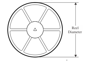
REEL DIMENSIONS
PACKAGE MATERIALS INFORMATION
24-Jul-2025
TAPE DIMENSIONS
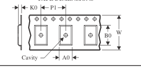
| A0 | Dimension designed to accommodate the component width |
| B0 | Dimension designed to accommodate the component length |
| K0 | Dimension designed to accommodate the component thickness |
| W | Overall width of the carrier tape |
| P1 | Pitch between successive cavity centers |
Reel Width (W1)
QUADRANT ASSIGNMENTS FOR PIN 1 ORIENTATION IN TAPE
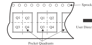
Sprocket Holes
User Direction of Feed
\*All dimensions are nominal
| Device | Package Type | Package Drawing | Pins | SPQ | Reel Diameter (mm) | Reel Width W1 (mm) | A0 (mm) | B0 (mm) | K0 (mm) | P1 (mm) | W (mm) | Pin1 Quadrant |
|---|---|---|---|---|---|---|---|---|---|---|---|---|
| AFE1203E/1K | SSOP | DL | 48 | 1000 | 330.0 | 32.4 | 11.35 | 16.2 | 3.1 | 16.0 | 32.0 | Q1 |
Pack Materials-Page 1
Page 14
PACKAGE MATERIALS INFORMATION
www.ti.com
24-Jul-2025
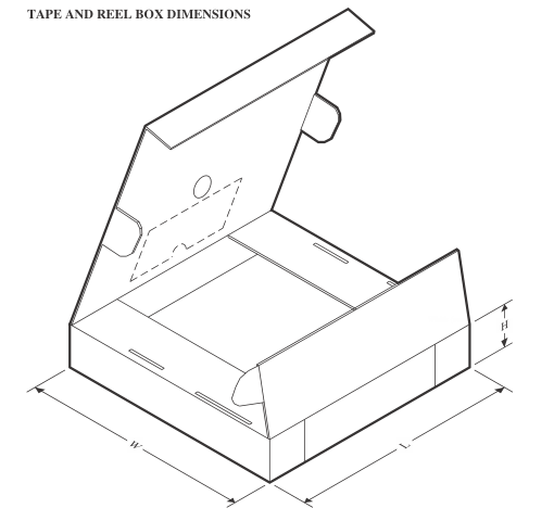
\*All dimensions are nominal
| Device | Package Type | Package Drawing | Pins | SPQ | Length (mm) | Width (mm) | Height (mm) |
|---|---|---|---|---|---|---|---|
| AFE1203E/1K | SSOP | DL | 48 | 1000 | 356.0 | 356.0 | 53.0 |
Pack Materials-Page 2
Page 15
IMPORTANT NOTICE AND DISCLAIMER
TI PROVIDES TECHNICAL AND RELIABILITY DATA (INCLUDING DATASHEETS), DESIGN RESOURCES (INCLUDING REFERENCE DESIGNS), APPLICATION OR OTHER DESIGN ADVICE, WEB TOOLS, SAFETY INFORMATION, AND OTHER RESOURCES “AS IS” AND WITH ALL FAULTS, AND DISCLAIMS ALL WARRANTIES, EXPRESS AND IMPLIED, INCLUDING WITHOUT LIMITATION ANY IMPLIED WARRANTIES OF MERCHANTABILITY, FITNESS FOR A PARTICULAR PURPOSE OR NON-INFRINGEMENT OF THIRD PARTY INTELLECTUAL PROPERTY RIGHTS. These resources are intended for skilled developers designing with TI products. You are solely responsible for (1) selecting the appropriate TI products for your application, (2) designing, validating and testing your application, and (3) ensuring your application meets applicable
standards, and any other safety, security, regulatory or other requirements. These resources are subject to change without notice. TI grants you permission to use these resources only for development of an application that uses the TI products described in the resource. Other reproduction and display of these resources is prohibited. No license is granted to any other TI intellectual property right or to any third party intellectual property right. TI disclaims responsibility for, and you fully indemnify TI and its representatives against any claims, damages, costs, losses, and liabilities arising out of your use of these resources. TI’s products are provided subject to TI’s Terms of Sale, TI’s General Quality Guidelines, or other applicable terms available either on
ti.com or provided in conjunction with such TI products. TI’s provision of these resources does not expand or otherwise alter TI’s applicable warranties or warranty disclaimers for TI products. Unless TI explicitly designates a product as custom or customer-specified, TI products are standard, catalog, general purpose devices. TI objects to and rejects any additional or different terms you may propose. IMPORTANT NOTICE
Copyright © 2026, Texas Instruments Incorporated
Last updated 10/2025