


 Download PDF
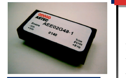
AEE02F12-49 ASTEC
Document overview
- PDF pages: 2
Technical content
Page 1

10 Watts
AEE00-12Vin
Input
Efficiency
Output
Special Features
- 10 W, Dual output
- 2:1 Input range
- 1.0" x 2.0" x 0.33 case
- Industry standard package
- Low Profile
- Low Cost
Environmental
Operating base temperature range:
-25°C to +100°C
Storage temperature: -40°C to +125°C
MTBF: 3 Million Hours (Belcore TR332)
Safety
UL UL1950 Recognition
CSA CSA22.2-950 Recognition
TUV EN60950 Recognition
Electrical Specs
Input range
9 to 18 VDC
78% typical (3.3V)
Voltage tolerance
±1.0%
Overall regulation
±1% max
Noise/ripple
1% Typ, 2% Max
Transient response
300 usec typical (50% step load change to within 3%Vo)
Temperature Regulation
±0.02 %Vo/°C
Switching frequency
330kHz
Isolation
I/O isolation
1500 VDC Input to Output 1000 VDC Input to Case 1000 VDC Output to Case
Isolation Resistance
300 Mohms
Europe (UK): 44 (1384) 842-211Asia (HK): 852-2437-9662
North America (USA): 1-888-41-ASTEC
Page 2
AMERICAS
5810 Van Allen Way Carlsbad, CA 92008 Telephone: 760-930-4600 Facsimile: 760-930-0698
Ordering Information
Input
Output
Voltage
Voltage
3.3V @ 2.55 A
9-18 V
5.0V @ 2 A
9-18 V
12V @ 0.84 A
9-18 V
15V @ 0.68 A
9-18 V
±5V @ ±1.0 A
9-18 V
±12V @ ±0.42 A
9-18 V
±15V @ ±0.33 A
9-18 V
NOTES: Enable Function
EUROPE
ASIA
Astec House, Waterfront Business Park
Units 2111-2116, Level 21
Merry Hill, Dudley
Tower1, Metroplaza
West Midlands, DY5 1LX, UK
223, Hing Fong Road
Telephone: 44 (1384) 842-211
Fwai Fong, New Territories Hong Kong
Facsimile: 44 (1384) 843-355
Telephone: 852-2437-9662 Facsimile: 852-2402-4426
Efficiency
Model Number
78%
AEE02F12-49
81%
AEE02A12-49
83%
AEE00B12-49
84%
AEE00C12-49
81%
AEE01AA12-4
83%
AEE00BB12-4
84%
AEE00CC12-4
- With the control pin floating (no connection), the unit is enabled and there is an output of 5V. 2. With the control pin Low (short to -Vin), the unit is enabled and there is an output of 5V. 3. With the control pin connected to an external logic signal (5V), the unit is disabled and there is no output. Trim Feature “9” at end of Model Number designates Trim option.
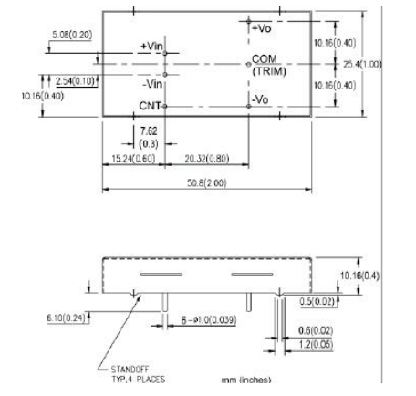
Mechanical Dimensions and Pin Assignments
Notes:
- 20 MHz bandwidth. An external 0.1 uf ceramic capacitor is recommended to be placed from +V out to comm. 2. All specifications are typical at nominal line, full load, and 25°C unless otherwise noted. 3. All specifications subject to change without notice. 4. Mechanical drawings are for reference only.
www.astecpower.com