
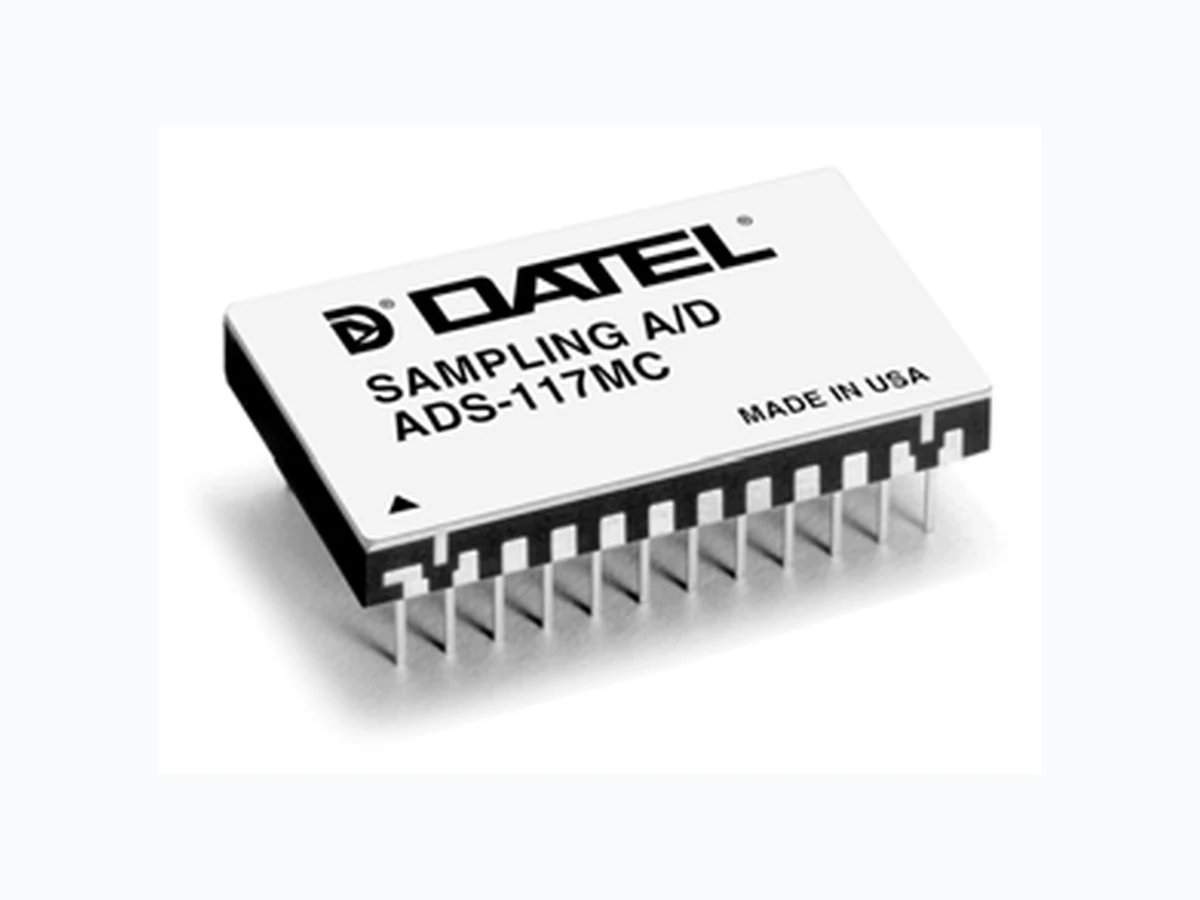
ADS-117 ETC
Document overview
- Manufacturer or author: Provided By www.digicamel.com(FREE DATASHEET DOWNLOAD SITE)
- PDF pages: 6
Technical content
Figure 1. ADS-117 Functional Block Diagram
FEATURES
- 12-bit resolution
- No missing codes
- 2MHz minimum throughput
- Functionally complete
- Small 24-pin DDIP
- Low-power, 1.6 Watts
- Three-state output buffers
- Samples to Nyquist frequencies GENERAL DESCRIPTION DATEL's ADS-117 is a functionally complete, 12-bit, 2MHz, sampling A/D converter. Its standard, 24-pin, double-width DIP contains a fast-settling sample-hold amplifier, a 12-bit subranging (two-step) A/D converter, a precision reference, three-state output register and all the timing and control logic necessary to operate from a single start convert pulse. Digital input and output levels are TTL. Total harmonic distortion (THD) and signal-to-noise ratio (including distortion) typically run –78dB and 70dB, respectively, with full scale inputs up to 100kHz. The ADS- 117 requires ±15V and +5V power supplies and typically consumes 1.6 Watts. Models are available for use in either commercial (0 to +70°C) or military (–55 to +125°C) operating temperature ranges. INPUT/OUTPUT CONNECTIONS PIN FUNCTION PIN FUNCTION
1 BIT 12 (LSB) 24 –15V SUPPLY
2 BIT 11 23 ANALOG GROUND
3 BIT 10 22 +15V SUPPLY
4 BIT 9 21 +10V REFERENCE
5 BIT 8 20 BIPOLAR
6 BIT 7 19 ANALOG INPUT
7 BIT 6 18 COMP BIN
8 BIT 5 17 ENABLE (1-12)
9 BIT 4 16 START CONVERT
10 BIT 3 15 EOC
11 BIT 2 14 DIGITAL GROUND
12 BIT 1 (MSB) 13 +5V SUPPLY
12 BIT 1 (MSB)
11 BIT 2
10 BIT 3
9 BIT 4
8 BIT 5
7 BIT 6
6 BIT 7
5 BIT 8
4 BIT 9
3 BIT 10
2 BIT 11
1 BIT 12 (LSB)
+10V REF. 21 START CONVERT 16 EOC 15 DIGITAL CORRECTION LOGIC DAC FLASH ADC COMP BIN 18 BUFFER S/H ANALOG INPUT 19
17 ENABLE (1-12)
+5V SUPPLY +15V SUPPLY ANALOG GROUND DIGITAL GROUND –15V SUPPLY
(TA = +25°C, ±VCC = +15V, +VDD =+5V, 2MHz sampling rate, and a minimum 3 minute warmup unless otherwise specified.) ANALOG INPUTS MIN. TYP . MAX. UNITS Input Voltage Range ➀ Bipolar — ±5 — Volts Unipolar — 0 to +10 — Volts Input Impedence 4.5 5 — k Ω Input Capacitance —6 1 5 p F DIGITAL INPUTS Logic Levels Logic "1" +2.0 — — Volts Logic "0" — — +0.8 Volts Logic Loading "1" — — +5 µA Logic Loading "0" — — –600 µA PERFORMANCE Resolution 12 Bits No Missing Codes (12 Bits; fin = 1MHz) 0 to +70°C Integral Non-Linearity 0°C to +70°C — ±1/2 ±3 LSB –55°C to +125°C — ±1 ±4 LSB Differential Non-Linearity Full Scale Absolute Accuracy (see Tech Note 1) Unipolar/Bipolar Zero Error 0°C to +70°C (see T ech Note 1) — ±0.07 ±0.38 %FSR Bipolar Offset Error 0°C to +70°C (see T ech Note 1) — ±0.1 ±0.38 %FSR Gain Error (see Tech Note 1) Internal Reference Voltage 0°C to +70°C +9.97 +10.0 +10.03 Volts –55°C to +125°C +9.95 — +10.05 Volts External Current —— 1 . 5 m A DYNAMIC PERFORMANCE Spurious Free Dynamic Range (–0.5dB) ➁ dc to 100kHz — –81 — dB 100kHz to 500kHz — –75 –70 dB 500kHz to 1MHz — –70 — dB Total Harm. Distort. (–0.5dB) dc to 100kHz — –78 — dB 100kHz to 500kHz — –73 –68 dB 500kHz to 1MHz — –71 — dB Input Bandwith (–3dB) Small Signal (–20dB input) 8 10 — MHz Large Signal (–0.5dB input) 7 9 — MHz Feedthrough (1MHz) –72 –74 — dB DYNAMIC PERF. (cont) MIN. TYP . MAX. UNITS SNR (wo/distortion, –0.5dB) dc to 100kHz 0°C to +70°C — 72 — dB –55°C to +125°C — 72 — dB 100kHz to 500kHz 0°C to +70°C 65 70 — dB –55°C to +125°C 65 70 — dB 500kHz to 1MHz 0°C to +70°C — 70 — dB –55°C to +125°C — 70 — dB SNR (and distort., –0.5dB) dc to 100kHz 0°C to +70°C — 70 — dB –55°C to +125°C — 69 — dB 100kHz to 500kHz 0°C to +70°C 64 70 — dB –55°C to +125°C 62 69 — dB 500kHz to 1MHz 0°C to +70°C — 69 — dB –55°C to +125°C — 69 — dB Two-tone Intermodulation Distortion (f in = 970kHz, 990kHz, fs = 2Mhz, –0.5dB) — –68 — dB Slew Rate — ±210 — V/µs Effect. Aperture Delay Time —— 1 6 n s Overvoltage Recovery Time; 20% — — 500 ns S/H Acq. Time, (to ±0.01%) 0 to +70°C — 155 165 ns –55°C to +125°C — 160 170 ns Conversion Rate 2 — — MHz OUTPUTS Output Coding Pin 18 High Pin 18 Low Logic Level Logic "1" +2.4 — — Volts Logic "0" — — +0.4 Volts Logic Loading "1" — — –160 µA Logic Loading "0" — — +6.4 mA POWER REQUIREMENTS Power Supply Ranges ➃ +15V Supply +1 4.25 +15.0 +15.75 Volts –15V Supply –14.25 –15.0 –15.75 Volts +5V Supply +4.75 +5.0 +5.25 Volts Power Supply Current +15V Supply — +48 +58 mA –15V Supply — –35 –45 mA +5V Supply — +75 +85 mA Power Dissipation — 1.6 1.9 Watts Power Supply Rejection — — ±0.07 %FSR%V PHYSICAL/ENVIRONMENTAL Operating Temp. Range, Case ADS-117MC 0 — +70 °C ADS-117MM, 883 –55 — +125 °C Storage Temperature Range –65 — +150 °C Thermal Impedance θjc — 3 — °C/W θca — 23 — °C/W Package Type 24-pin, metal-sealed, ceramic DDIP Weight 0.42 ounces (12 grams) ABSOLUTE MAXIMUM RATINGS PARAMETERS LIMITS UNITS +15V Supply (Pin 22) 0 to +16 Volts –15V Supply (Pin 24) 0 to –16 Volts +5V Supply (Pin 13) 0 to +6.0 Volts Digital Inputs (Pin 16, 17, 18) –0.3 to +V DD +0.3 Volts Analog Input (Pin 19) –9 to +15 Volts Lead Temp. (10 seconds) +300 °C 6.02 (SNR + Distortion) – 1.76 + 20 log Full Scale Amplitude Actual Input Amplitude ➂ Effective bits is equal to: ➀ See T able 1 also ➁ Same specifications for in-band harmonics. ➃ For ±12V, +5V operation, contact DATEL Staight binary/Offset binary Complementary binary Complementary offset binary
Table 3. Output Coding OFF. BINARY COMP . OFF. BIN. Figure 5. FFT Analysis of ADS-117
DATEL makes no representation that the use of its products in the circuits described herein, or the use of other technical information contained herein, will not infringe upon existing or future patent rights. The descriptions contained herein do not imply the granting of licenses to make, use, or sell equipment constructed in accordance therewith. Specifications are s ubject to change without notice. The DATEL logo is a registered DATEL, Inc. trademark. DS-0230F 07/04 MECHANICAL DIMENSIONS INCHES (mm)
ORDERING INFORMATION
ADS-EVAL1 Evaluation Board (without ADS-117) HS-24 Heat Sink for all ADS-117 models MODEL NUMBER OPERATING TEMP . RANGE ADS-117MC 0 to +70°C ADS-117MM –55 to +125°C ADS-117/883 –55 to +125°C For MIL-STD-883 product specification or availability of surface-mount packaging, contact DATEL. Receptacles for PC mounting can be ordered through AMP Inc., Part # 3-331272-8 (Component Lead Socket), 24 required. 0.200 MAX. (5.080) 0.235 MAX. (5.969) 0.600 ±0.010 (15.240) 0.80 MAX. (20.32) 0.100 TYP. (2.540) 0.100 (2.540) 0.018 ±0.002 (0.457) 0.100 (2.540) 0.040 (1.016) 1.31 MAX. (33.27) 11 2 1324 1.100 (27.940) 0.190 MAX. (4.826) 0.010 (0.254) +0.002 –0.001 SEATING PLANE 0.025 (0.635) Dimension Tolerances (unless otherwise indicated): 2 place decimal (.XX) ±0.010 (±0.254) 3 place decimal (.XXX) ±0.005 (±0.127) Lead Material: Kovar alloy Lead Finish: 50 microinches (minimum) gold plating over 100 microinches (nominal) nickel plating PIN 1 INDEX ISO 9001ISO 9001 /C82/C69/C71/C73/C83/C84/C69/C82/C69/C68 DATEL, Inc. 11 Cabot Boulevard, Mansfield, MA 02048-1151 Tel: (508) 339-3000 (800) 233-2765 Fax: (508) 339-6356 Internet: www.datel.com E-mail:sales@datel.com DATEL (UK) LTD. Tadley, England Tel: (01256)-880444 DATEL S.A.R.L. Montigny Le Bretonneux, France Tel: 1-34-60-01-01 DATEL GmbH München, Germany Tel: 89-544334-0 DATEL KK Tokyo, Japan Tel: 3-3779-1031, Osaka Tel: 6-6354-2025 DATEL China, Shanghai, China Tel:011-86-51317199