

 Download PDF
ADC76 BURR-BROWN
Document overview
- Manufacturer or author: Provided By digicamel.com
- PDF pages: 8
Technical content
Successive Approx. Register (SAR) 16-Bit D/A Converter Reference Clock Parallel Digital Output Short Cycle Convert Command Input Range Select Comparator In Clock Rate Control Clock Out Status Serial Out 16-Bit ANALOG-TO-DIGITAL CONVERTER International Airport Industrial Park • Mailing Address: PO Box 11400 • Tucson, AZ 85734 • Street Address: 6730 S. Tucson Blvd. • Tucson, AZ 85706 Tel: (520) 746-1111 • Twx: 910-952-1111 • Cable: BBRCORP • Telex: 066-6491 • FAX: (520) 889-1510 • Immediate Product Info: (800) 548-6132
DESCRIPTION
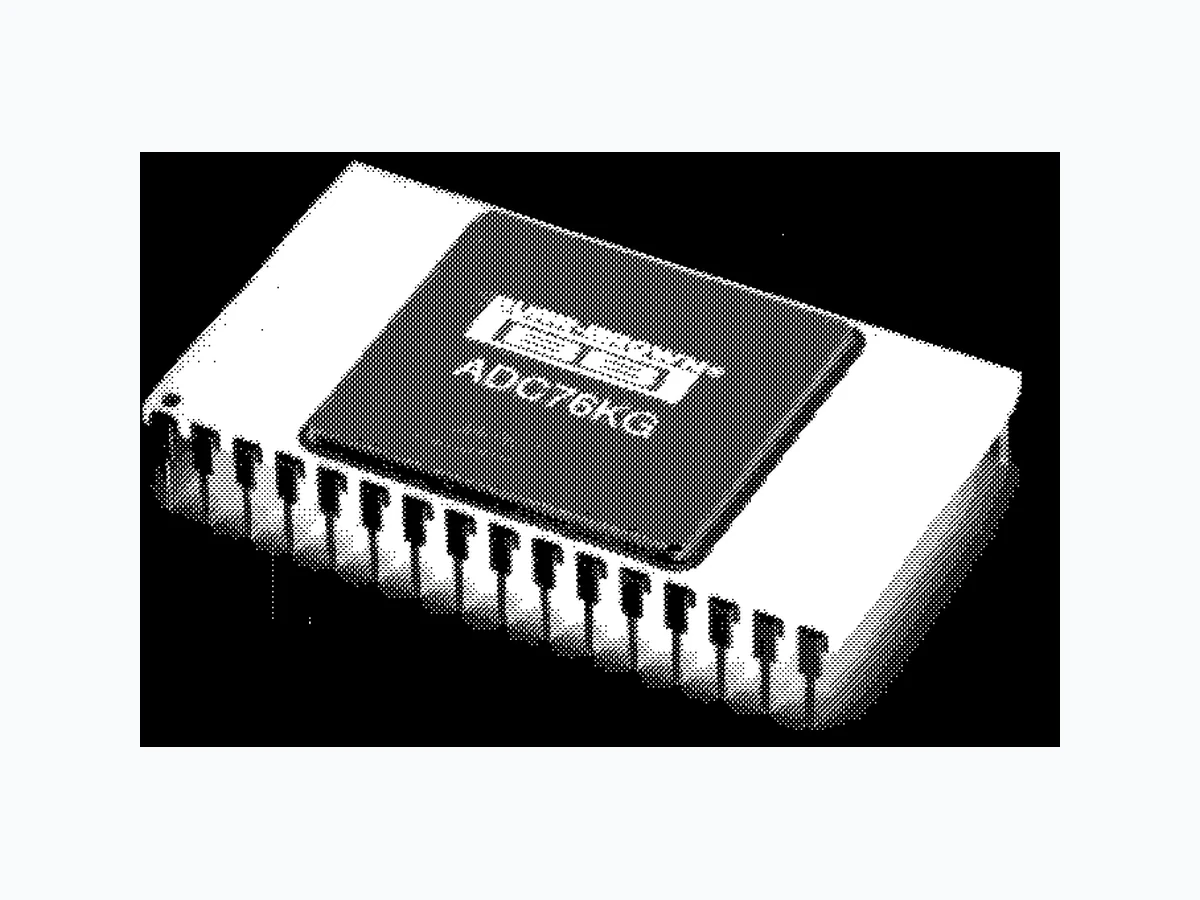
The ADC76 is a high quality, 16-bit successive ap- proximation analog-to-digital converter. The ADC76 uses state-of-the-art laser-trimmed IC thin-film resis- tors and is packaged in a hermetic 32-pin dual-in-line package. The converter is complete with internal ref- erence, short cycling capabilities, serial output, and thin-film scaling resistors, which allow selection of analog input ranges of ±2.5V, ±5V, ±10V, 0 to +5V, 0 to +10V and 0 to +20V. It is specified for operation over two temperature ranges: 0°C to +70°C (J, K) and –25°C to +85°C (A, B). Data is available in parallel and serial form with corresponding clock and status output. All digital inputs and outputs are TTL-compatible. Power supply voltages are ±15VDC and +5VDC. ADC76
FEATURES
l LINEARITY ERROR: ±0.003% max (KG, BG) l NO MISSING CODES GUARANTEED FROM –25 °C TO +85°C l 17µs CONVERSION TIME (16-Bit) l SERIAL AND PARALLEL OUTPUTS © 1990 Burr-Brown Corporation PDS-1063A Printed in U.S.A. December, 1993
At +25°C, and rated power supplies, unless otherwise noted. ADC76J, K ADC76A, B MODEL MIN TYP MAX MIN TYP MAX UNITS RESOLUTION 16 * Bits ANALOG INPUTS Voltage Ranges: Bipolar ±2.5, ±5, ±10 * V Unipolar 0 to +5, 0 to +10 * V 0 to +20 * Impedance (Direct Input) 0 to +5V, ±2.5V 2.5 * k Ω 0 to +10V, ±5.0V 5 * k Ω 0 to +20V, ±10V 10 * k Ω DIGITAL INPUTS (1) Convert Command Positive pulse 50ns wide (min) trailing edge (“1” to “0” initiates conversion) Logic Loading 1 * TTL Load TRANSFER CHARACTERISTICS ACCURACY Gain Error Offset Error: Unipolar(2) ±0.05 ±0.1 * * % of FSR (3) Bipolar(2) ±0.1 ±0.2 * * % of FSR Linearity Error: K, B ±0.003 * % of FSR J, A ±0.006 * % of FSR Inherent Quantization Error ±1/2 * LSB Differential Linearity Error ±0.003 * % of FSR Noise (3σ, p-p) ±0.001 ±0.003 * * % of FSR POWER SUPPLY SENSITIVITY ±15VDC 0.003 * % of FSR/%V S +5VDC 0.001 * % of FSR/%V S CONVERSION TIME (4)
14 Bits 15 * µs
15 Bits 16 * µs
16 Bits 17 * µs
WARM-UP TIME 5* M i n DRIFT Gain ±15 * ppm/ °C Offset: Unipolar ±2 ±4 * * ppm of FSR/ °C Bipolar ±10 * ppm of FSR/ °C Linearity ±2 ±3 * * ppm of FSR/ °C No Missing Codes Temp Range OUTPUT DIGITAL DATA (All codes complementary) Parallel Output Codes(5): Unipolar CSB * Bipolar COB, CTC (6) * Output Drive 2 * TTL Loads Serial Data Code (NRZ) CSB, COB * Output Drive 2 * TTL Loads Status Logic “1” during conversion * Status Output Drive 2 * TTL Loads Internal Clock: Clock Output Drive 2 * TTL Loads Frequency(7) 933 1400 * * kHz POWER SUPPLY REOUIREMENTS Power Consumption 0.655 * W Rated Voltage: Analog ±11.4 ±15 ±1 6 *** V D C Digital +4.75 +5 +5.25 * * * VDC Supply Drain: +15VDC +10 +15 * * mA +5VDC +17 +20 * * mA TEMPERATURE RANGE Specification 0 +70 –25 +85 °C Storage –55 +125 * * °C *Specification same as ADC76J, K. (2) Adjustable to zero. See “Optional External Gain and Offset Adjustment” section. (3) FSR means Full Scale Range. For example, unit connected for ±10V range has 20V FSR. (4) Conversion time may be shortened with “Short Cycle” set for lower resolution and with use of Clock Rate Control. See “Optional Conversion Time Adjustment” section. The Clock Rate Control (pin 23) should be connected to Digital Common for specified conversion time. Short Cycle (pin 32) should be left open for 16-bit resolution or connected to the n + 1 digital output for n-bit resolution. For example, connect Short Cycle to Bit 15 (pin 15) for 14-bit resolution. For resolutions less than 16 bits, pin 32 should also be tied to +5V through a 2kΩ resistor. (5) See Table I. CSB = Complementary Straight Binary, COB = Complementary Offset Binary, CTC = Complementary Two’s Complement. (6) CTC coding obtained by inverting MSB (pin 1). (7) Adjustable with Clock Rate Control from approximately 933kHz to 1.4MHz.
MODEL max (% of FSR) TEMPERATURE RANGE 1-24 25-99 100-249 ADC76AG ±0.006 –25 °C to +85°C ADC76BG ±0.003 –25 °C to +85°C ADC76JG ±0.006 0 °C to +70°C ADC76KG ±0.003 0 °C to +70°C PIN CONFIGURATION Top View DIP
PACKAGE INFORMATION
MODEL PACKAGE NUMBER (1) ADC76JG 32-Pin Hermetic DIP 172-5 ADC76KG 32-Pin Hermetic DIP 172-5 ADC76AG 32-Pin Hermetic DIP 172-5 ADC76BG 32-Pin Hermetic DIP 172-5 NOTE: (1) For detailed drawing and dimension table, please see end of data sheet, or Appendix D of Burr-Brown IC Data Book. ABSOLUTE MAXIMUM SPECIFICATIONS
ORDERING INFORMATION
The information provided herein is believed to be reliable; however, BURR-BROWN assumes no responsibility for inaccuracies or omissions. BURR-BROWN assumes no responsibility for the use of this information, and all use of such information shall be entirely at the user’s own risk. Prices and specifications are subject to change without notice. No patent rights or licenses to any of the circuits described herein are implied or granted to any third party. BURR-BROWN does not authorize or warrant any BURR-BROWN product for use in life support devices and/or systems. 16-Bit D/A Converter 16-Bit SAR 5kΩ5kΩ 6.3kΩ Reference Clock MSB Bit 1 1 Bit 2 2 Bit 3 3 Bit 4 4 Bit 5 5 Bit 6 6 Bit 7 7 Bit 8 8 Bit 9 9 Bit 10 10 Bit 11 11 Bit 12 12 (LSB for 13 Bits) Bit 13 13 Bit 15 15 (LSB for 14 Bits) Bit 14 14 Bit 16 16 Comparator
32 Short Cycle
31 Convert Command
29 Gain Adjust
27 Comparator In
26 Bipolar Offset
23 Clock Rate Control
22 Analog Common
(1) 21 –15V Supply
20 Clock Out
18 Status
19 Digital Common
17 Serial Out
NOTE: (1) Metal lid is connected to pin 22 (Analog Common).
TA = +25°C, VCC = ±15V unless otherwise noted. FIGURE 1. Input vs Output for an Ideal Bipolar A/D step over the range of the A/ D converter is 1LSB, ±1/2LSB. to clock, and valid data to status. mentary offset binary (COB) for bipolar input signal ranges. by inverting the MSB (pin 1). 14-bit resolution, parallel data output, with ±10V input. apply to the serial data output except for the CTC code. *See Table I for Digital Code Definitions.