
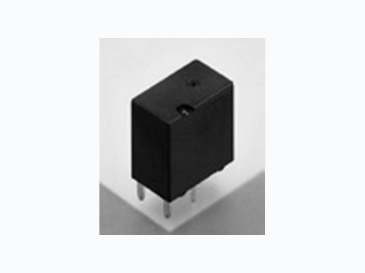
ACTE2H1 PANASONIC
Document overview
- Manufacturer or author: Provided By digicamel.com
- PDF pages: 9
Technical content
ASCTB97E 202103Panasonic Corporation 2021
FEATURES
Compact and high-capacity 25 A load switching Pin in Paste compliant model added. Miniature PC Board, Twin Type, 1 Form C Automotive Relay TE RELAYS Automotive Relays TYPICAL APPLICATIONS Powered windows, Automatic door locks, Powered mirrors, Powered sunroof, Powered seats, Lift gates and Slide door closers, etc. ( Unit: mm ) < Protective construction > High heat-resistant type: Sealed Pin in Paste compliant type: Flux tight 1212 13.513.5 13.513.5 7.27.2 1 3.61 3.6 1212 1414 1414 7.27.2 1 3.61 3.6 1212 1212 ORDERING INFORMATION (PART NO.) ACTE Contact arrangement 2: 1 Form C 3: 1 Form C × 2 ( 8 pins ) 5: 1 Form C × 2 ( 10 pins ) Heat resistance / Protective construction H: High heat-resistant type / Sealed R: Pin in Paste compliant type / Flux tight Coil resistance 1: 110 Ω 2: 160 Ω 3: 220 Ω Contact type Nil: Standard type C: Standard type ( Ag alloy / Cu clad ) industrial.panasonic.com/ac/e/2021.04 0ü 1 0ü
Automotive Relays TE RELAYS Panasonic Corporation Electromechanical Control Business Division industrial.panasonic.com/ac/e/ ASCTB97E 202103Panasonic Corporation 2021 TYPES Contact arrangement Contact type Rated coil voltage Coil resistance Part No. Packing Heat resistance Carton (1-tube) CaseHigh heat-resistant type Pin in Paste compliant type
1 Form C
12 V DC
110 Ω ACTE2H1 ACTE2R1 50 pcs. 2,000 pcs. 160 Ω ACTE2H2 ACTE2R2 220 Ω ACTE2H3 ACTE2R3 Standard type (Ag alloy / Cu clad) 110 Ω ACTE2CH1 ACTE2CR1 160 Ω ACTE2CH2 ACTE2CR2 220 Ω ACTE2CH3 ACTE2CR3
1 Form C x 2
(8 pins) Standard type 110 Ω ACTE3H1 ACTE3R1 40 pcs. 160 Ω ACTE3H2 ACTE3R2 220 Ω ACTE3H3 ACTE3R3 Standard type (Ag alloy / Cu clad) 110 Ω ACTE3CH1 ACTE3CR1 160 Ω ACTE3CH2* ACTE3CR2 220 Ω ACTE3CH3 ACTE3CR3 (10 pins) Standard type 110 Ω ACTE5H1 ACTE5R1 160 Ω ACTE5H2 ACTE5R2 220 Ω ACTE5H3 ACTE5R3 Standard type (Ag alloy / Cu clad) 110 Ω ACTE5CH1 ACTE5CR1 160 Ω ACTE5CH2 ACTE5CR2 220 Ω ACTE5CH3 ACTE5CR3 * Please order "ACTE3CH2A05V" (standard stock part number). The letter of suffix "V" is not marked on the device (relay). It is only marked on the inner and outer carton. Coil data Rated coil voltage Operate (Set) voltage (at 20°C)(Initial) Release (Reset) voltage (at 20°C)(Initial) Rated operating current [±10%] (at 20°C) Coil resistance [±10%] (at 20°C) Rated operating power (at 20°C) Usable voltage range Max. 5.5 V DC Min. 0.6 V DC 109 mA 110 Ω 1,309 mW 10 to 16 V DCMax. 6.5 V DC Min. 0.8 V DC 75 mA 160 Ω 900 mW Max. 7.7 V DC 54.5 mA 220 Ω 655 mW RATING 0ü 2 0ü
Automotive Relays TE RELAYS Panasonic Corporation Electromechanical Control Business Division industrial.panasonic.com/ac/e/ ASCTB97E 202103Panasonic Corporation 2021 Specifications Item Specifications Contact data Contact arrangement 1 Form C, 1 Form C x 2 Contact resistance Contact material Ag alloy Rated switching capacity (resistive) N.O. side: 20 A 14 V DC, N.C. side: 10 A 14 V DC Max. carrying current (initial)* 1 25 A/2 min (coil applied voltage 12 V DC, at 20°C) Min. switching load (resistive)* 2 1 A 14 V DC (at 20°C) Insulated resistance (initial) Min. 100 MΩ (at 500 V DC, Measurement at same location as “Dielectric strength” section) Dielectric strength (initial) Between open contacts 500 Vrms for 1 min. (detection current: 10 mA) Between contacts and coil 500 Vrms for 1 min. (detection current: 10 mA) Time characteristics (initial) Operate (Set) time (at rated voltage) Max. 10 ms (at 20°C, without contact bounce time) Release (Reset) time (at rated voltage) Max. 10 ms (at 20°C, without contact bounce time) (without diode) Shock resistance Functional Min. 100 m/s2 (approx. 10 G) (half-wave pulse of sine wave: 11 ms, detection time: 10 µs) Destructive Min. 1,000 m/s2 (approx. 100 G) (half-wave pulse of sine wave: 6 ms) Vibration resistance Functional 10 to 100 Hz, Min. 44.1 m/s2 (approx. 4.5 G) (detection time: 10 µs) Destructive 10 to 500 Hz, Min. 44.1 m/s2 (approx. 4.5 G) Time of vibration for each direction; X, Y direction: 2 hours, Z direction: 4 hours Expected life Mechanical Min. 107 (at 120 times/min) Electrical*4 <Resistive load> Min. 105 at rated switching capacity operating frequency: ON 1s, OFF 9s <Motor load> Min. 105 at 25 A 14 V DC at motor lock operating frequency: ON 0.5s, OFF 9.5s Conditions Conditions for usage, transport and storage* High heat-resistant type/Pin in Paste compliant type Ambient temperature: - 40 to +110°C Humidity: 2 to 85% RH (Avoid icing and condensation) Unit weight Single type: approx. 3.5 g, Twin type: approx. 6.5 g Notes: *1.Depends on connection conditions. Also, this does not guarantee repeated switching. We recommend that you confirm operation under actual conditions. *2. This value can change due to the switching frequency, environmental conditions, and desired reliability level, therefore it is recommended to check this with the actual load. *3. The upper operation ambient temperature limit is the maximum temperature that can satisfy the coil temperature rise value. For details, please refer to the “Automotive Relay Users Guide”. Please inquire our sales representative if you will be using the relay in a high temperature atmosphere (110°C). *4.Do not use for lamp loads, electric discharge lamp loads, any other lamp loads and capacitor loads. Please inquire our sales representative for details. *If the relay is used continuously for long periods of time with coils on both sides in an energized condition, breakdown might occur due to abnormal heating depending on the carrying condition. Therefore, please inquire our sales representative when using with a circuit that causes an energized condition on both sides simultaneously. REFERENCE DATA 1.-(1) Coil temperature rise (at room temperature) Sample: ACTE3H2, 3 pcs. Carrying current: 0 A, 10 A, 20 A Ambient temperature: Room temperature 140 160 180 120 100 12 16 1814 20 A 10 A 0 A Coil applied voltage, V Temperature rise, °C 1.-(2) Coil temperature rise (at 110°C) Sample: ACTE3H2, 3 pcs. Carrying current: 0 A, 10 A, 20 A Ambient temperature: 110°C 140 160 180 120 100 12 16 1814 20 A 20 A 10 A 0 A Coil applied voltage, V Temperature rise, °C 2. Ambient temperature and usable voltage range Sample: ACTE3H2 -40 -20 20 40 60 80 120 1000 Operate voltage (Cold start) Ambient temperature, °C Coil applied voltage, V Usable voltage range 0ü 3 0ü
Automotive Relays TE RELAYS Panasonic Corporation Electromechanical Control Business Division industrial.panasonic.com/ac/e/ ASCTB97E 202103Panasonic Corporation 2021 3. Distribution of operate (set) and release (reset) voltage Sample: ACTE3H2, 40 × 2 pcs. Operate voltage Release voltage 1 0 2 3 5 4 6 7 8 Voltage, v Quantity, n 4. Distribution of operate (set) and release (reset) time Sample: ACTE3H2, 40 × 2 pcs. Operate time Release time 1 0 2 3 5 4 6 7 8 * Without diode Quantity, n Time, ms 5.Electrical life test (Motor lock) M Sample: ACTE3H2, 3 pcs. Load: 25 A 14 V DC Power window motor actual load (lock condition) Operating frequency: ON 0.5 s, OFF 9.5 s Ambient temperature: Room temperature Circuit: 1050 1050 Change of operate (set) and release (reset) voltage Load current waveform Change of contact resistance Contact welding: 0 time Miscontact: 0 time Contact welding: 0 time Miscontact: 0 time N.C. side N.O. side Operate voltageOperate voltage Release voltageRelease voltage Ave. Max. Min. Max. Ave. Min. Max.Max. Min. Ave.(N.C.) Ave.(N.O.) Min. 100 ms 5 A Current value: 25 A No. of operations, × 104 Operate and release voltage, V No. of operations, × 104 Contact resistance, mΩ 0ü 4 0ü
Automotive Relays TE RELAYS Panasonic Corporation Electromechanical Control Business Division industrial.panasonic.com/ac/e/ ASCTB97E 202103Panasonic Corporation 2021 COMN.C. N.O. COIL COIL 5.2 4.8 4.8 3.7 2.2 0.5 1.6 dia. 2×1.1 dia. 2×1.5 dia. Tolerance: ± 0.1 (1) 4.8 3.72.2 (0.6) 5.2 0.5 +0.3 ー0.11 +0.3 ー0.1 4.8 12±0.5 0.4 13.5±0.53.5±0.5 0.5 0.6 +0.3 ー0.1 +0.3 ー0.1 0.25 +0.3 ー0.1 7.2±0.5 0.3 +0.3 ー0.1 0.3 +0.3 ー0.1 1.2 +0.3 ー0.1 Max. 1.0 A surface level Pre-soldering (all terminals) * Dimensions (thickness and width) of terminal is measured after pre-soldering. Intervals between terminals is measured at A surface level. Tolerance Max. 1 mm: ± 0.1 1 to 3 mm : ± 0.2 Min. 3 mm : ± 0.3 DIMENSIONS CAD The CAD data of the products with a “CAD” mark can be downloaded from our Website. Unit: mm CAD External dimensions PC board pattern (BOTTOM VIEW) Schematic (BOTTOM VIEW)
1 Form C type
Twin type (8 pins) COMN.C. COM N.O. COIL COIL 6.4 2.2 3. 1 5.2 3.7 4.8 3. 1 5.2 11.6 2×1.5 dia. 4×1.1 dia. 2×1.6 dia. Tolerance: ± 0.1 12±0.5 13.6±0.5 0.4 13.5±0.53.5±0.5 0.5 0.6 3.1 5.2 6.4 2.2 3.74.8 (0.6) 3.1 5.2 (1) 0.3 +0.3 ー0.1 0.3 +0.3 ー0.1 1.2 +0.3 ー0.1 0.3 +0.3 ー0.1 0.3 +0.3 ー0.1 1.2 +0.3 ー0.1 +0.3 ー0.1 +0.3 ー0.1 +0.3 ー0.1 +0.3 ー0.1 0.25 +0.3 ー0.1 11.6 Max. 1.0 A surface level Pre-soldering (all terminals) * Dimensions (thickness and width) of terminal is measured after pre-soldering. Intervals between terminals is measured at A surface level. Tolerance Max. 1 mm: ± 0.1 1 to 3 mm : ± 0.2 Min. 3 mm : ± 0.3 CAD External dimensions PC board pattern (BOTTOM VIEW) Schematic (BOTTOM VIEW) 0ü 5 0ü
Automotive Relays TE RELAYS Panasonic Corporation Electromechanical Control Business Division industrial.panasonic.com/ac/e/ ASCTB97E 202103Panasonic Corporation 2021 Twin type (10 pins) COMN.C. COM N.O. N.C. N.O. COIL COIL 2.2 3.7 4.8 3. 1 5.2 3. 1 5.2 3.2 3.2 3.2 1 1 2×1.6 dia. 4×1.1 dia. 4×1.5 dia. Tolerance: ± 0.1 3.2 3.2 3.2 12±0.5 13.6±0.5 0.4 13.5±0.53.5±0.5 0.5 0.6 3.1 5.2 2.2 3.74.8 (0.6) 3.1 5.2(1) 1 1 0.3 +0.3 ー0.1 0.3 +0.3 ー0.1 1.2 +0.3 ー0.1 0.3 +0.3 ー0.1 0.3 +0.3 ー0.1 1.2 +0.3 ー0.1 +0.3 ー0.11 +0.3 ー0.1 +0.3 ー0.11 +0.3 ー0.1 +0.3 ー0.1 +0.3 ー0.1 0.25 +0.3 ー0.1 Max. 1.0 A surface level Pre-soldering (all terminals) * Dimensions (thickness and width) of terminal is measured after pre-soldering. Intervals between terminals is measured at A surface level. Tolerance Max. 1 mm: ± 0.1 1 to 3 mm : ± 0.2 Min. 3 mm : ± 0.3 CAD External dimensions PC board pattern (BOTTOM VIEW) Schematic (BOTTOM VIEW) Pin in Paste compliant type COMN.C. N.O. COIL COIL 5.2 4.8 4.8 3.7 2.2 0.5 1.6 dia. 2×1.1 dia. 2×1.5 dia. Tolerance: ± 0.1 (1) 7.2±0.512±0.5 0.9 Max. 1.0 14±0.53±0.5 0.5 0.6 +0.3 ー0.1 +0.3 ー0.1 0.25 +0.3 ー0.1 A surface level Pre-soldering (all terminals) 4.8 3.72.2 (0.6) 5.2 0.5 0.3 +0.3 ー0.1 0.3 +0.3 ー0.1 1.2 +0.3 ー0.1 +0.3 ー0.1 +0.3 ー0.1 4.8 * Dimensions (thickness and width) of terminal is measured after pre-soldering. Intervals between terminals is measured at A surface level. Tolerance Max. 1 mm: ± 0.1 1 to 3 mm : ± 0.2 Min. 3 mm : ± 0.3 CAD External dimensions PC board pattern (BOTTOM VIEW) Schematic (BOTTOM VIEW) 0ü 6 0ü
Automotive Relays TE RELAYS Panasonic Corporation Electromechanical Control Business Division industrial.panasonic.com/ac/e/ ASCTB97E 202103Panasonic Corporation 2021 Twin type (8 pins) Pin in Paste compliant type COMN.C. COM N.O. COIL COIL 6.4 2.2 3. 1 5.2 3.7 4.8 3. 1 5.2 11.6 2×1.5 dia. 4×1.1 dia. 2×1.6 dia. Tolerance: ± 0.1 Air hole 12±0.5 13.6±0.5 0.9 14±0.53±0.5 0.5 0.6 3.1 5.2 6.4 2.2 3.74.8 (0.6) 3.1 5.2 (1) 0.3 +0.3 ー0.1 0.3 +0.3 ー0.1 1.2 +0.3 ー0.1 0.3 +0.3 ー0.1 0.3 +0.3 ー0.1 1.2 +0.3 ー0.1 +0.3 ー0.1 +0.3 ー0.1 +0.3 ー0.1 +0.3 ー0.1 0.25 +0.3 ー0.1 11.6 Max. 1.0 A surface level Pre-soldering (all terminals) * Dimensions (thickness and width) of terminal is measured after pre-soldering. Intervals between terminals is measured at A surface level. Tolerance Max. 1 mm: ± 0.1 1 to 3 mm : ± 0.2 Min. 3 mm : ± 0.3 CAD External dimensions PC board pattern (BOTTOM VIEW) Schematic (BOTTOM VIEW) Pin in Paste compliant type COMN.C. COM N.O. N.C. N.O. COIL COIL 2.2 3.7 4.8 3. 1 5.2 3. 1 5.2 3.2 3.2 3.2 1 1 2×1.6 dia. 4×1.1 dia. 4×1.5 dia. Tolerance: ± 0.1 3.2 3.2 3.2 12±0.5 13.6±0.5 0.9 14±0.53±0.5 0.5 0.6 3.1 5.2 2.2 3.74.8 (0.6) 3.1 5.2(1) 1 1 0.3 +0.3 ー0.1 0.3 +0.3 ー0.1 1.2 +0.3 ー0.1 0.3 +0.3 ー0.1 0.3 +0.3 ー0.1 1.2 +0.3 ー0.1 +0.3 ー0.11 +0.3 ー0.1 +0.3 ー0.11 +0.3 ー0.1 +0.3 ー0.1 +0.3 ー0.1 0.25 +0.3 ー0.1 Air hole Max. 1.0 A surface level Pre-soldering (all terminals) * Dimensions (thickness and width) of terminal is measured after pre-soldering. Intervals between terminals is measured at A surface level. Tolerance Max. 1 mm: ± 0.1 1 to 3 mm : ± 0.2 Min. 3 mm : ± 0.3 CAD External dimensions PC board pattern (BOTTOM VIEW) Schematic (BOTTOM VIEW) Twin type (10 pins) 0ü 7 0ü
Automotive Relays TE RELAYS Panasonic Corporation Electromechanical Control Business Division industrial.panasonic.com/ac/e/ ASCTB97E 202103Panasonic Corporation 2021 0 85 110-40 Humidity(%RH) Ambient temperature(°C) Allowable range Avoid icing when used at temperatures lower than 0°C Avoid con densation when used at temperatures higher than 0°C GUIDELINES FOR USAGE t1 t2 t1=60 to 120 s t2=Less than 30 s t3=Less than 5 s T1=150 to 180°C T2=230°C or more T3=Less than 250°C Please refer to "the latest product specifications" when designing your product.
- Requests to customers: https://industrial.panasonic.com/ac/e/salespolicies/ 1) Cautions for mounting (1) The temperature profile shows the temperature at the soldering portion on the PC board surface. (2) Depending on the mounting density condition, reflow heating method, and PC board type (metal etc.), the relay's exterior and interior temperature may become extremely high. Therefore, please confirm well under the actual use condition before use. 2) The other cautions of reflow soldering (1) When soldering condition is out of recommendation, the relay performance may be adversely affected. If soldering conditions are out of our recommendation, please inquire our sales representative before operation. (2) Please check the effect at the actual soldering because heat stress to relay is changed by PC board type and manufacturing process condition (3) Solder creepage, wettability or soldering strength will be affected by the mounting condition or soldering material. Please check the actual production condition in detail. (4) Do not wash the relay as failures may occur. (5) This product is not plastic sealed type. Please perform coating with sufficient attention to avoid infiltration of the solvent to the inside. Also, please pay careful attention to use and store them with no contamination of foreign material. Mounting and cleaning conditions for Pin in Paste compliant type Atmosphere when using, storing and transporting 1) Ambient temperature, humidity and air pressure during usage, transport, and storage of the relay. (1) Temperature: –40 to +110°C (High heat resistant type/Pin in Paste compliant type) (2) Humidity: 2 to 85% RH (Avoid icing and condensation) (3) Air pressure: 86 to 106 kPa The humidity range varies with the temperature. Use within the range indicated in the graph below. [Temperature and humidity range for usage, transport, and storage] For general cautions for use, please refer to the "Automotive Relay Users Guide". When soldering this relay, please observe the following conditions. [I.R.S method (recommended)] (Recommended number of reflow: 1 time) 2) Water condensation Water condensation occurs when the ambient temperature drops suddenly from a high temperature and humidity, or, the relay is suddenly transferred from a low ambient temperature to a high temperature and humidity. Condensation causes the failures like insulation deterioration, wire disconnection and rust etc. Panasonic Corporation does not guarantee the failures caused by condensation. The heat conduction by the equipment may accelerate the cooling of relay itself, and the condensation may occur. Please confirm no condensation in the worst condition of the actual usage. (Special attention should be paid when high temperature heating parts are close to the relay. Also, please consider the condensation may occur inside of the relay.) 3) Icing Please check the icing when an ambient temperature is lower than 0°C. Icing means, the moisture contained in the surrounding environment and inside the relay freezes when the ambient temperature falls below the freezing point. The icing causes the sticking of movable portion, the operation delay and the contact conduction failure etc. Panasonic Corporation does not guarantee the failures caused by the icing. The heat conduction by the equipment may accelerate the cooling of relay itself and the icing may occur. Icing condition is changed by ambient environment, please make sure to confirm no icing in the worst condition of the actual usage. 0ü 8 0ü
Electromechanical Control Business Division industral.panasonic.com/ac/e/ Specifications are subject to change without notice. 1006, Oaza Kadoma, Kadoma-shi, Osaka 571-8506, Japan ©Panasonic Corporation 2021 ASCTB97E 202103