
ACS2T NELLSEMI
Document overview
- Manufacturer or author: Provided By www.digicamel.com(FREE DATASHEET DOWNLOAD SITE)
- PDF pages: 7
Technical content
TRIACs, 2AAC Switch
FEATURES
High noise immunity - static dV/dt ≥ 500 V/µS High tolerance to external severe application environment such as EMC High voltage blocking capability
APPLICATIONS
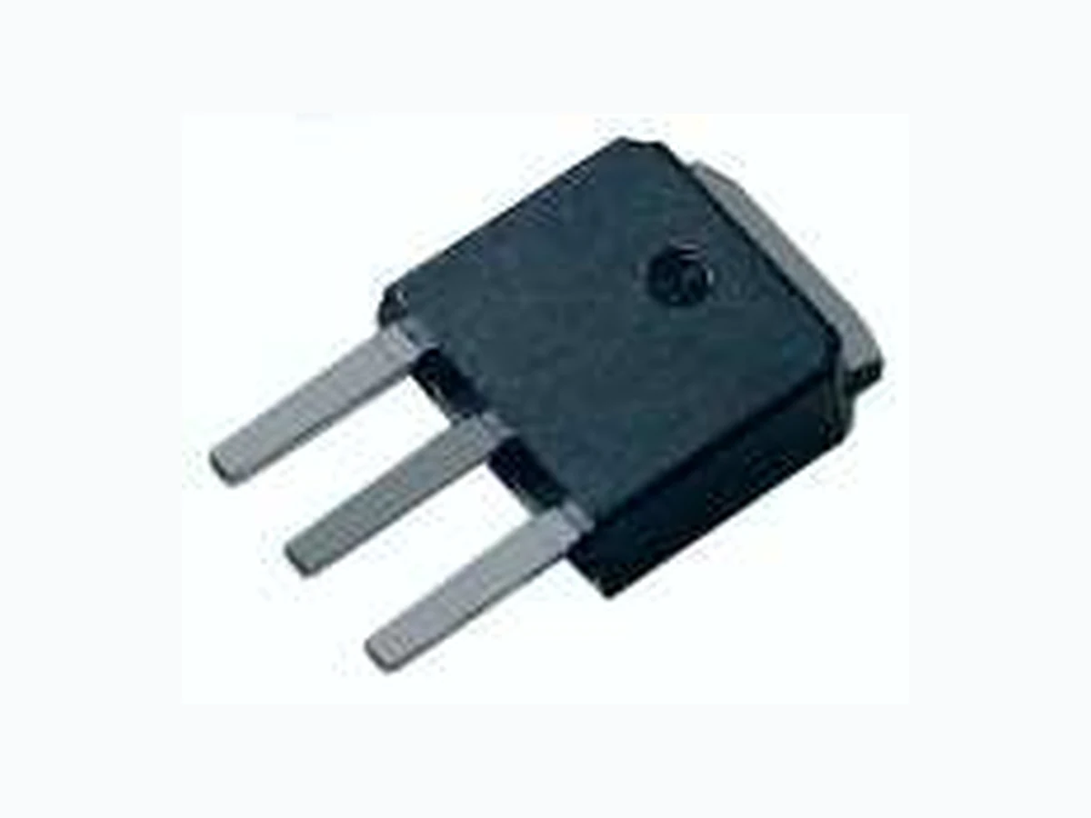
ACS2T series triacs provide high dV/dt rate with strong resistance to electromagnetic interference, intended for use in AC static switching in appliances and industrial control systems,driving low power highly inductive loads like relay, solenoid, pump, fan, and micro-motor . ITO-220AB/TO-220F ( 2TxxAF)ACS T1(1) T2(2) G(3) TO-92 ( 2Txx E)ACS SOT-223 ( 2TxxS)ACS 2 3 MAIN FEATURES SYMBOL VALUE UNIT IT(RMS) V /VDRM RRM IGT 2 A V mA10/25 1000 SYMBOL IT(RMS) 2 SOT-223/TO-251-4R/TO-252-4R ITSM Non repetitive surge peak on-state A 2I t 2A s dI/dt 50 IGM PG(AV) PGM - 40 to + 150 ºC A/µs A A W UNITV ALUE 20F = 50 Hz F = 60 Hz T = 10 msp T = 8.3 msp t = 10 msp F = 100 Hz T = 80ºCJ T =80ºCJ T =125ºCJ T < 2µsp TJ ABSOLUTE MAXIMUM RATINGS PARAMETER TEST CONDITIONS T = 103°CC Tstg - 40 to + 125 Peak gate power dissipation Average gate power dissipation Peak gate current RMS on-state current (full sine wave) current (full cycle, T initial = 25 °C)J 2l t Value for fusing Critical rate of rise of on-state current l = 2xl , t ≤100nsG GT r Stroage temperature range Operating junction temperature range T = 80ºCJ Repetitive peak off-state voltage Repetitive peak reverse voltage VDRM VRRM T = 25ºCJ 1000 V 0.1 TO-220F (insulate) TO-92 T = 90°CC T = 100°CC www.nellsemi.com Page 1 of 7 (ACS2TxxF ) ( ACS 2TxxG) 1 2 TO-251-4R (I-PAK) TO-252-4R (D-PAK)
Ⅰ-Ⅱ-Ⅲ MAX. mA Ⅰ-Ⅱ-Ⅲ Ⅰ-Ⅱ-Ⅲ MAX. mA MIN. QUADRANT ACS2Txxxx V = 12 V, R = 33ΩD L V = V , R = 3.3KΩ, T = 125°CD DRM L j I = 100 mAT I = 1.2 IG GT V = 67% V , gate open, T = 125°CD DRM j V V mA V/µs UNITTEST CONDITIONS SYMBOL 3 quadrants (1)IGT VGT VGD (2)IH dV/dt IL (T = 25 ºC unless otherwise specified)JELECTRICAL CHARACTERISTICS 1000 1.3 I-Ⅲ SW CW MAX. 0.2 600 (2)RD MAX. IDRM IRRM V = VD DRM MAX. Note 1: Minimum l is guaranted at 5% of l max.GT GT Note 2: For both polarities of T2 referenced to T1. Dynamic resistance T = 125°CJ T = 25°CJ T = 125°CJ 250 1000 µA STATIC CHARACTERISTICS V ALUETEST CONDITIONS SYMBOL V = VR RRM STATIC CHARACTERISTICS UNITV ALUESYMBOL (2)VTO MAX.Threshold voltage T = 125°CJ 0.90 V (2)VTM MAX.I = 2.8A, t = 380 µsTM P T = 25°CJ 1.55 mΩ THERMAL RESISTANCE Rth(j-c) Junction to case (AC) °C/W UNITV ALUESYMBOL TO-251-4R/TO-252-4R 4.5 PRODUCT SELECTOR PART NUMBER VOL T AGE (xx) SENSITIVITY PACKAGETYPE 1000 V VACS2TxxE-SW 3 Quadrants10mA TO -92 TO-92 SOT-223 TO-220F(insulate) 11.2 5.8 7.5 ACS2TxxE-CW ACS2TxxG-SW ACS2TxxG-CW ACS2TxxAF-SW ACS2TxxAF-CW V 3 Quadrants25mA TO-92 V 3 Quadrants10mA TO-251-4RACS2TxxF-SW ACS2TxxF-CW V 3 Quadrants25mA V 3 Quadrants10mA TO-252-4R V 3 Quadrants25mA TO-252-4R V 3 Quadrants10mA TO-220F V 3 Quadrants25mA TO-220F www.nellsemi.com Page 2 of 7 VACS2TxxS-SW 3 Quadrants10mA SOT -223 SOT -223VACS2TxxS-CW 3 Quadrants25mA TO-251-4R
ORDERING INFORMATION
Note: xx = voltage, yy = sensitivity ORDERING TYPE MARKING PACKAGE WEIGHT ,BASE Q TY DELIVERY MODE TO-92 0.2g 500 BagACS2TxxE-YY ORDERING INFORMATION SCHEME T riac series Current V oltage 2 = 2A 10 = 1000V ACS 2 T 10 Package type AF = TO-220F( )insulate AC switch S - T&R Packing Blank = Bulk T&R = 7" Tape and Reel ACS2T Series RoHS RoHS ACS2TxxF-YY TO-251-4R(I-PAK) 0.4g 80 Tube ACS2TxxG-YY TO -252-4R(D-PAK) 0.38g 80 Tube ACS2TxxAF-YY TO-220F 2.5g 50 Tube ACS2TxxE-YY ACS2TxxF-YY ACS2TxxG-YY ACS2TxxAF-YY E = TO-92 F = TO-251-4R (I-PAK) G = TO-252-4R (D-PAK) S = SOT-223 www.nellsemi.com Page 3 of 7 ACS2TxxS-YY SOT -223 980g 4000 7" T&RACS2TxxS-YY
Fig.2 RMS on-state current vs. case temperature Fig.1 Maximum power dissipation vs. RMS on-state current 0 0 .5 1 1.5 2 2 .5 Fig.3 On-state characteristics (maximum values) 0 25 50 Fig.4 Surge peak on-state current vs. number of cycles. 1 10 100 1000 Number of cycles Fig.5 Relative variation of gate trigger current versus junction temperature (typical values). Fig.6 Relative variation of holding current and latching current versus junction temperature (typical values). l [T ] / l [T = 25 °C]GT J GT J 3.0 2.5 2.0 1.5 1.0 0.5 0.0 140120100806040200-20-40 3.0 2.5 2.0 1.5 1.0 0.5 0.0 -40 -20 0 20 40 60 80 100 120 140 l l [T ] / l l [T = 25 °C]H, L J H, L J ACS2T Series RoHS RoHS l (A)T(RMS ) 75 100 125 α=180° TO-251-4R/TO-252-4R/ SOT-223 TO-220F(lns) TO-92 P(W) IT(RMS)(A) lTM(A) T =25°CJ T =125°CJ VTM(V) t=20mS Full cycle T (°C)J lGT3 l &lGT1 GT2 lH lL www.nellsemi.com Page 4 of 7 T (ºC)C
www.nellsemi.com Page 5 of 7 TO-252-4R (D-PAK) TO-251-4R (I-PAK) 21 3 21 3 T1(1) T2(3) G(2)
5.20(0.205) 4.45(0.175) TO-92 5.33(0.210) 4.58(0.180) 0.50(0.020) 0.40(0.016) 0.50(0.020) 0.40(0.016) 0.50(0.020) 0.40(0.016) 1.40(0.055) 1.14(0.045) 1.40(0.055) 1.14(0.045) 4.20(0.165) 3.20(0.126) 12.70(0.500)Min. 1 3 2 Ø ACS2T Series RoHS RoHS www.nellsemi.com Page 6 of 7 T1(1) T2(2) G(3) Case Style
T1(1) T2(2) G(3) ITO-220AB(TO-220F) 1 3 3.3 3.1 13.7 13.5 16.0 15.8 2.8 2.6 0.48 0.44 2.54 TYP 0.9 0.72.54 TYP 16.4 15.4 7.1 6.7 3.7 3.2 10.6 10.4 4.8 4.6 10° 2.85 2.65 3.4 3.1 www.nellsemi.com Page 7 of 7 T1(1) T2(2) G(3) SOT-223 3.00±0 .10 7.00±0 .30 4.60±0 .10 6.50±0 .20 1.65±0 .15 0.26±0 .04 0.90 1.75±0 .25 3.50±0 .20 10° Max .