

 Download PDF
AB08X5 ABRACON
Document overview
- PDF pages: 33
Technical content
Page 1
| AB08X5 Real-Time Clock Family | ||
| Date of Issue: October 16, 2014 | 3.0 x 3.0 mm | |
| Page 1 of 33 | Abracon Drawing #453567 | Revision: C |
Features
- Ultra-low supply current (all at 3V): - 14 nA with RC oscillator - 22 nA with RC oscillator and Autocalibration - 55 nA with crystal oscillator
- Baseline timekeeping features: - 32.768 kHz crystal oscillator with integrated load capacitor/resistor
- Counters for hundredths, seconds, minutes, hours, date, month, year, century, and weekday - Alarm capability on all counters - Programmable output clock generation (32.768 kHz to 1 year) - Countdown timer with repeat function - Automatic leap year calculation
- Advanced timekeeping features: - Integrated power optimized RC oscillator - Advanced crystal calibration to ± 2 ppm - Advanced RC calibration to ± 16 ppm - Automatic calibration of RC oscillator to crystal oscillator
- Watchdog timer with hardware reset - 256 bytes of general purpose RAM
- Power management features: - Automatic switchover to VBAT - External interrupt monitor - Programmable low battery detection threshold - Programmable analog voltage comparator
- I2C (up to 400 kHz) and 3-wire or 4-wire SPI (up to 2 MHz) serial interfaces available
- Operating voltage 1.5-3.6 V
- Clock and RAM retention voltage 1.5-3.6 V
- Operating temperature –40 to 85 °C
- All inputs include Schmitt Triggers
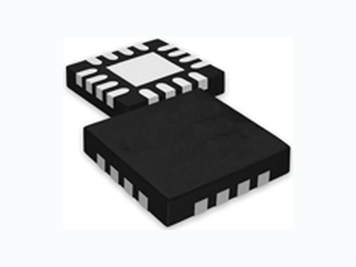
- 3x3 mm QFN-16 package
Applications
- Smart cards
- Wireless sensors and tags
- Medical electronics
- Utility meters
- Data loggers
- Appliances
- Handsets
- Consumer electronics
- Communications equipment
Description
The ABRACON AB08X5 Real-Time Clock family provides a groundbreaking combination of ultra-low power coupled with a highly sophisticated feature set. With power requirements significantly lower than any other industry RTC (as low as 14 nA), these are the first semiconductors based on innovative SPOTTM (Subthreshold Power Optimized Technology) CMOS platform. The AB08X5 includes on-chip oscillators to provide minimum power consumption, full RTC functions including battery backup and programmable counters and alarms for timer and watchdog functions, and either an I2C or SPI serial interface for communication with a host controller.
Disclaimer: AB08X5 series of devices are based on innovative SPOT technology, proprietary to Ambiq Micro.
Page 2
| AB08X5 Real-Time Clock Family | ||
| Date of Issue: October 16, 2014 | 3.0 x 3.0 mm | |
| Page 2 of 33 | Abracon Drawing #453567 | Revision: C |
1. Family Summary
The AB08X5 family consists of several members (see Table 1). All devices are supplied in a standard 3x3 mm QFN-16 package. Members of the software and pin compatible AB18X5 RTC family are also listed.
Table 1: Family Summary
| Part # | Baseline Timekeeping | Advanced Timekeeping | Power Management | Interface | |||||||
|---|---|---|---|---|---|---|---|---|---|---|---|
| XT Osc | Number of GP Outputs | RC Osc | Calib/ Auto- calib | Watch- dog | RAM (B) | VBAT Switch | Reset Mgmt | Ext Int | Power Switch and Sleep FSM | ||
| AB0805 | ■ | 3 | ■ | ■ | ■ | 256 | ■ | ■ | I2C | ||
| AB0815 | ■ | 2 | ■ | ■ | ■ | 256 | ■ | ■ | SPI | ||
| Software and Pin Compatible AB18X5 Family Components | |||||||||||
| AB1805 | ■ | 4 | ■ | ■ | ■ | 256 | ■ | ■ | ■ | ■ | I2C |
| AB1815 | ■ | 3 | ■ | ■ | ■ | 256 | ■ | ■ | ■ | ■ | SPI |
Page 3
| AB08X5 Real-Time Clock Family | ||
| Date of Issue: October 16, 2014 | 3.0 x 3.0 mm | |
| Page 3 of 33 | Abracon Drawing #453567 | Revision: C |
2. Functional Description
Figure 1 illustrates the AB08X5 functional design.
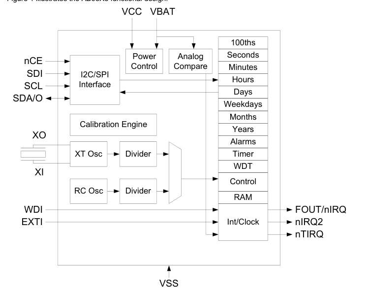
Figure 1. Detailed Block Diagram
The AB08X5 serves as a full function RTC for host processors such as microcontrollers. The AB08X5 includes 3 distinct feature groups: 1) baseline timekeeping features, 2) advanced timekeeping features, and 3) basic power management features. Functions from each feature group may be controlled via I/O offset mapped registers. These registers are accessed using either an I2C serial interface (e.g., in the AB0805) or a SPI serial interface (e.g., in the AB0815). Each feature group is described briefly below and in greater detail in subsequent sections.
The baseline timekeeping feature group supports the standard 32.786 kHz crystal (XT) oscillation mode for maximum frequency accuracy with an ultra-low current draw of 55 nA. The baseline timekeeping feature group also includes a standard set of counters monitoring hundredths of a second up through centuries. A complement of countdown timers and alarms may additionally be set to initiate interrupts or resets on several of the outputs.
Page 4
| AB08X5 Real-Time Clock Family | ||
| Date of Issue: October 16, 2014 | 3.0 x 3.0 mm | |
| Page 4 of 33 | Abracon Drawing #453567 | Revision: C |
The advanced timekeeping feature group supports two additional oscillation modes: 1) RC oscillator mode, and 2) Autocalibration mode. At only 14 nA, the temperature-compensated RC oscillator mode provides an even lower current draw than the XT oscillator for applications with reduced frequency accuracy requirements. A proprietary calibration algorithm allows the AB08X5 to digitally tune the RC oscillator frequency and the XT oscillator frequency with accuracy as low as 2 ppm at a given temperature. In Autocalibration mode, the RC oscillator is used as the primary oscillation source and is periodically calibrated against the XT oscillator. Autocalibration may be done automatically every 8.5 minutes or 17
minutes and may also be initiated via software. This mode enables average current draw of only 22 nA with frequency accuracy similar to the XT oscillator. The advanced timekeeping feature group also includes a rich set of input and output configuration options that enables the monitoring of external interrupts (e.g., pushbutton signals), the generation of clock outputs, and watchdog timer functionality.
Power management features built into the AB08X5 enable it to operate as a backup device in both linepowered and battery-powered systems. An integrated power control module automatically detects when main power (VCC) falls below a threshold and switches to backup power (VBAT). 256B of ultra-low leakage RAM enable the storage of key parameters when operating on backup power. The AB08X5 also includes digitally-tunable voltage detection on the backup power supply.
Page 5
| AB08X5 Real-Time Clock Family | ||
| Date of Issue: October 16, 2014 | 3.0 x 3.0 mm | |
| Page 5 of 33 | Abracon Drawing #453567 | Revision: C |
3. AB08X5 Example Applications
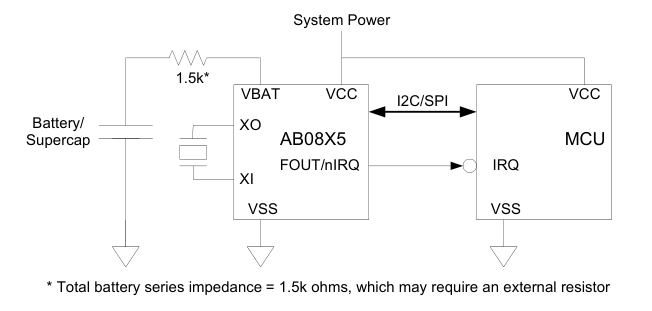
3.1 Battery Backed Up RTC
The most common AB08X5 application is a battery backed up RTC, which maintains time and may hold data in RAM. The AB08X5 is normally powered from a system power supply, which may be a larger battery. The AB08X5 is continuously charging a supercapacitor or rechargeable battery via the internal trickle charger. When the main power supply goes away, the AB08X5 automatically switches to the VBAT supply and maintains time and RAM data at very low battery supply currents.
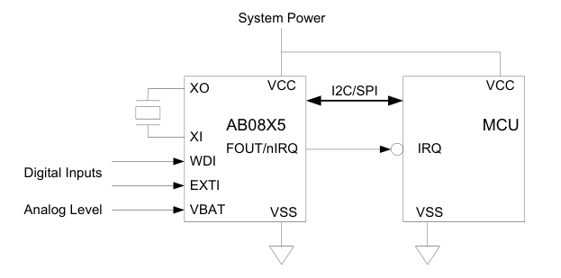
3.2 RTC with Interrupt Aggregation
The flexible inputs of the AB08X5 can be used to aggregate a variety of interrupt sources, including external digital inputs, analog levels, timers and alarms into a single interrupt source to an MCU.
Page 6
| AB08X5 Real-Time Clock Family | ||
| Date of Issue: October 16, 2014 | 3.0 x 3.0 mm | |
| Page 6 of 33 | Abracon Drawing #453567 | Revision: C |
4. Package Pins
4.1 Pin Configuration and Connections
Figure 2 and Table 2 show the QFN-16 pin configurations for the AB08X5 parts. Pins labeled NC must be left unconnected. The thermal pad, pin 17, on the QFN-16 packages must be connected to VSS.
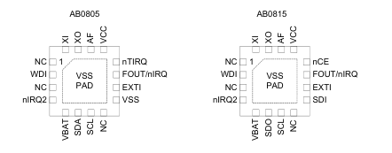
Figure 2. Pin Configuration Diagram
Table 2: Pin Connections
| Pin Name | Pin Type | Function | Pin Number | |
|---|---|---|---|---|
| AB0805 | AB0815 | |||
| VSS | Power | Ground | 9,17 | 17 |
| VCC | Power | System power supply | 13 | 13 |
| XI | XT | Crystal input | 16 | 16 |
| XO | XT | Crystal output | 15 | 15 |
| AF | Output | Autocalibration filter | 14 | 14 |
| VBAT | Power | Battery power supply | 5 | 5 |
| SCL | Input | I2C or SPI interface clock | 7 | 7 |
| SDO | Output | SPI data output | 6 | |
| SDI | Input | SPI data input | 9 | |
| nCE | Input | SPI chip select | 12 | |
| SDA | Input | I2C data input/output | 6 | |
| EXTI | Input | External interrupt input | 10 | 10 |
| WDI | Input | Watchdog reset input | 2 | 2 |
| FOUT/nIRQ | Output | Int 1/function output | 11 | 11 |
| nIRQ2 | Output | Int 2 output | 4 | 4 |
| nTIRQ | Output | Timer interrupt output | 12 | |
Page 7
| AB08X5 Real-Time Clock Family | ||
| Date of Issue: October 16, 2014 | 3.0 x 3.0 mm | |
| Page 7 of 33 | Abracon Drawing #453567 | Revision: C |
4.2 Pin Descriptions
Table 3 provides a description of the pin connections.
Table 3: Pin Descriptions
| Pin Name | Description |
|---|---|
| VSS | Ground connection. In the QFN-16 packages the ground slug on the bottom of the package must be connected to VSS. |
| VCC | Primary power connection. If a single power supply is used, it must be connected to VCC. |
| VBAT | Battery backup power connection. If a backup battery is not present, VBAT must be connected directly to VSS, but it may also be used to provide the analog input to the internal comparator (see Analog- Comparator). |
| XI | Crystal oscillator input connection. |
| XO | Crystal oscillator output connection. |
| AF | Autocalibration filter connection. A 47pF ceramic capacitor must be placed between this pin and VSS for improved Autocalibration mode timing accuracy. |
| SCL | I/O interface clock connection. It provides the SCL input in both I2C and SPI interface parts. A pull-up resistor is required on this pin. |
| SDA (only available in I2C environments) | I/O interface I2C data connection. A pull-up resistor is required on this pin. |
| SDO (only available in SPI environments) | I/O interface SPI data output connection. |
| SDI | I/O interface SPI data input connection. |
| nCE (only available in SPI environments) | I/O interface SPI chip select input connection. It is an active low signal. A pull-up resistor is recom- mended to be connected to this pin to ensure it is not floating. A pull-up resistor also prevents inadver- tent writes to the RTC during power transitions. |
| EXTI | External interrupt input connection. It may be used to generate an External 1 interrupt with polarity selected by the EX1P bit if enabled by the EX1E bit. The value of the EXTI pin may be read in the EXIN register bit. This pin does not have an internal pull-up or pull-down resistor and so one must be added externally. It must not be left floating or the RTC may consume higher current. Instead, it must be con- nected directly to either VCC or VSS if not used. |
| WDI | Watchdog Timer reset input connection. It may also be used to generate an External 2 interrupt with polarity selected by the EX2P bit if enabled by the EX2E bit. The value of the WDI pin may be read in the WDIN register bit. This pin does not have an internal pull-up or pull-down resistor and so one must be added externally. It must not be left floating or the RTC may consume higher current. Instead, it must be connected directly to either VCC or VSS if not used. |
Page 8
| AB08X5 Real-Time Clock Family | ||
| Date of Issue: October 16, 2014 | 3.0 x 3.0 mm | |
| Page 8 of 33 | Abracon Drawing #453567 | Revision: C |
Table 3: Pin Descriptions
| Pin Name | Description |
|---|---|
| FOUT/nIRQ | Primary interrupt output connection. This pin is an open drain output. An external pull-up resistor must be added to this pin. It should be connected to the host device and is used to indicate when the RTC can be accessed via the serial interface. FOUT/nIRQ may be configured to generate several signals as a function of the OUT1S field(see 0x11 - Control2). FOUT/nIRQ is also asserted low on a power up until the AB08X5 has exited the reset state and is accessible via the I/O interface. 1. FOUT/nIRQ can drive the value of the OUT bit. 2. FOUT/nIRQ can drive the inverse of the combined interrupt signal IRQ (see Interrupts). 3. FOUT/nIRQ can drive the square wave output (see 0x13 - SQW) if enabled by SQWE. 4. FOUT/nIRQ can drive the inverse of the alarm interrupt signal AIRQ (see Interrupts). |
| nIRQ2 | 1. Secondary interrupt output connection. It is an open drain output. This pin can be left floating if not used. nIRQ2 may be configured to generate several signals as a function of the OUT2S field (see 0x11 - Control2). nIRQ2 can drive the value of the OUTB bit. 2. nIRQ2 can drive the square wave output (see 0x13 - SQW) if enabled by SQWE. 3. nIRQ2 can drive the inverse of the combined interrupt signal IRQ(see Interrupts). 4. nIRQ2 can drive the inverse of the alarm interrupt signal AIRQ(see Interrupts). 5. nIRQ2 can drive either sense of the timer interrupt signal TIRQ. |
| nTIRQ (only available in I2C environments) | Timer interrupt output connection. It is an open drain output. nTIRQ always drives the active low nTIRQ signal. If this pin is used, an external pull-up resistor must be added to this pin. If the pin is not used, it can be left floating. |
Page 9
| AB08X5 Real-Time Clock Family | ||
| Date of Issue: October 16, 2014 | 3.0 x 3.0 mm | |
| Page 9 of 33 | Abracon Drawing #453567 | Revision: C |
5. Electrical Specifications
5.1 Absolute Maximum Ratings
Table 4 lists the absolute maximum ratings.
Table 4: Absolute Maximum Ratings
| SYMBOL | PARAMETER | TEST CONDITIONS | MIN | TYP | MAX | UNIT |
|---|---|---|---|---|---|---|
| V CC | System Power Voltage | -0.3 | 3.8 | V | ||
| V BAT | Battery Voltage | -0.3 | 3.8 | V | ||
| V I | Input voltage | VCC Power state | -0.3 | V + 0.3 CC | V | |
| V I | Input voltage | VBAT Power state | -0.3 | V + 0.3 BAT | V | |
| V O | Output voltage | VCC Power state | -0.3 | V + 0.3 CC | V | |
| V O | Output voltage | VBAT Power state | -0.3 | V + 0.3 BAT | V | |
| I I | Input current | -10 | 10 | mA | ||
| I O | Output current | -20 | 20 | mA | ||
| V ESD | ESD Voltage | CDM | ±500 | V | ||
| HBM | ±4000 | V | ||||
| I LU | Latch-up Current | 100 | mA | |||
| T STG | Storage Temperature | -55 | 125 | °C | ||
| T OP | Operating Temperature | -40 | 85 | °C | ||
| T SLD | Lead temperature | Hand soldering for 10 seconds | 300 | °C | ||
| T REF | Reflow soldering temperature | Reflow profile per JEDEC J- STD-020D.1 | 260 | °C |
5.2 Power Supply Parameters
Figure 3 and Table 5 describe the power supply and switchover parameters. See Power Control and Switching for a detailed description of the operations.
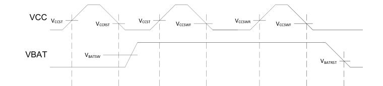
| POR | VCC Power | POR | VCC Power | VBAT Power | VCC Power | VBAT Power | POR |
Power State
Figure 3. Power Supply Switchover
Page 10
| AB08X5 Real-Time Clock Family | ||
| Date of Issue: October 16, 2014 | 3.0 x 3.0 mm | |
| Page 10 of 33 | Abracon Drawing #453567 | Revision: C |
For Table 5, TA = -40 °C to 85 °C, TYP values at 25 °C.
Table 5: Power Supply and Switchover Parameters
| SYMBO L | PARAMETER | PWR | TYPE | POWER STATE | TEST CONDITIONS | MIN | TYP | MAX | UNIT |
|---|---|---|---|---|---|---|---|---|---|
| V CC | System Power Voltage | VCC | Static | VCC Power | Clocks operating and RAM and registers retained | 1.5 | 3.6 | V | |
| V CCIO | VCC I/O Interface Voltage | VCC | Static | VCC Power | I2C or SPI opera- tion | 1.5 | 3.6 | V | |
| V CCST | VCC Start-up Voltage(1) | VCC | Rising | POR -> V Power CC | 1.6 | V | |||
| V CCRST | VCC Reset Voltage | VCC | Falling | VCC Power -> POR | V < V or BAT BAT,MIN no V BAT | 1.3 | 1.5 | V | |
| V CCSWR | VCC Rising Switch-over Threshold Voltage | VCC | Rising | VBAT Power -> VCC Power | V ≥ V BAT BATRST | 1.6 | 1.7 | V | |
| V CCSWF | VCC Falling Switch-over Threshold Voltage | VCC | Falling | VCC Power -> VBAT Power | V ≥ V BAT BATSW,MIN | 1.2 | 1.5 | V | |
| V CCSWH | VCC Switchover Thresh- old Hysteresis(2) | VCC | Hyst. | VCC Power <-> VBAT Power | 70 | mV | |||
| V CCFS | VCC Falling Slew Rate to switch to VBAT state(4) | VCC | Falling | VCC Power -> VBAT Power | V < V CC CCSW,MAX | 0.7 | 1.4 | V/ms | |
| V BAT | Battery Voltage | VBAT | Static | VBAT Power | Clocks operating and RAM and reg- isters retained | 1.4 | 3.6 | V | |
| V BATSW | Battery Switchover Volt- age Range(5) | VBAT | Static | VCC Power -> VBAT Power | 1.6 | 3.6 | V | ||
| V BATRST | Falling Battery POR Volt- age(7) | VBAT | Falling | VBAT Power -> POR | V < V CC CCSWF | 1.1 | 1.4 | V | |
| V BMRG | V Margin above BAT V (3) CC | VBAT | Static | V Power BAT | 200 | mV | |||
| V BATESR | V supply series resis- BAT tance(6) | VBAT | Static | V Power BAT | 1.0 | 1.5 | k | ||
| (1) V must be above V to exit the POR state, independent of the V voltage. CC CCST BAT (2) Difference between V and V . CCSWR CCSWF (3) V must be higher than V by at least this voltage to ensure the AB08X5 remains in the VBAT Power state. BAT CC (4) Maximum VCC falling slew rate to guarantee correct switchover to VBAT Power state. There is no V falling slew rate CC requirement if switching to the VBAT power source is not required. (5) V voltage to guarantee correct transition to VBAT Power state when V falls. BAT CC (6) Total series resistance of the power source attached to the VBAT pin. The optimal value is 1.5k, which may require an external resistor. VBAT power source ESR + external resistor value = 1.5k (7) V is also the static voltage required on V for register data retention. BATRST BAT | |||||||||
Page 11
| AB08X5 Real-Time Clock Family | ||
| Date of Issue: October 16, 2014 | 3.0 x 3.0 mm | |
| Page 11 of 33 | Abracon Drawing #453567 | Revision: C |
5.3 Operating Parameters
Table 6 lists the operating parameters.
For Table 6, TA = -40 °C to 85 °C, TYP values at 25 °C.
Table 6: Operating Parameters
| SYMBOL | PARAMETER | TEST CONDITIONS | V CC | MIN | TYP | MAX | UNIT |
|---|---|---|---|---|---|---|---|
| V T+ | Positive-going Input Thresh- old Voltage | 3.0V | 1.5 | 2.0 | V | ||
| 1.8V | 1.1 | 1.25 | |||||
| V T- | Negative-going Input Thresh- old Voltage | 3.0V | 0.8 | 0.9 | V | ||
| 1.8V | 0.5 | 0.6 | |||||
| I ILEAK | Input leakage current | 3.0V | 0.02 | 80 | nA | ||
| C I | Input capacitance | 3 | pF | ||||
| V OH | High level output voltage on push-pull outputs | 1.7V – 3.6V | 0.8•V CC | V | |||
| V OL | Low level output voltage | 1.7V – 3.6V | 0.2•V CC | V | |||
| I OH | High level output current on push-pull outputs | V = 0.8●V OH CC | 1.7V | -2 | -3.8 | mA | |
| 1.8V | -3 | -4.3 | |||||
| 3.0V | -7 | -11 | |||||
| 3.6V | -8.8 | -15 | |||||
| I OL | Low level output current | V = 0.2●V OL CC | 1.7V | 3.3 | 5.9 | mA | |
| 1.8V | 6.1 | 6.9 | |||||
| 3.0V | 17 | 19 | |||||
| 3.6V | 18 | 20 | |||||
| I OLEAK | Output leakage current | 1.7V – 3.6V | 0.02 | 80 | nA |
Page 12
| AB08X5 Real-Time Clock Family | ||
| Date of Issue: October 16, 2014 | 3.0 x 3.0 mm | |
| Page 12 of 33 | Abracon Drawing #453567 | Revision: C |
5.4 Oscillator Parameters
Table 7 lists the oscillator parameters.
VCC = 1.7 to 3.6V, TYP values at 25 °C and 3.0V.
For Table 7, TA = -40 °C to 85 °C unless otherwise indicated.
Table 7: Oscillator Parameters
| SYMBOL | PARAMETER | TEST CONDITIONS | MIN | TYP | MAX | UNIT |
|---|---|---|---|---|---|---|
| F XT | XI and XO pin Crystal Fre- quency | 32.768 | kHz | |||
| F OF | XT Oscillator failure detection frequency | 8 | kHz | |||
| C INX | Internal XI and XO pin capac- itance | 1 | pF | |||
| C EX | External XI and XO pin PCB capacitance | 1 | pF | |||
| OA XT | XT Oscillation Allowance | At 25°C using a 32.768 kHz crystal | 270 | 320 | kΩ | |
| F RCC | Calibrated RC Oscillator Fre- quency(1) | Factory Calibrated at 25°C, VCC = 2.8V | 128 | Hz | ||
| F RCU | Uncalibrated RC Oscillator Frequency | Calibration Disabled (OFF- SETR = 0) | 89 | 122 | 220 | Hz |
| J RCCC | RC Oscillator cycle-to-cycle jitter | Calibration Disabled (OFF- SETR = 0) – 128 Hz | 2000 | ppm | ||
| Calibration Disabled (OFF- SETR = 0) – 1 Hz | 500 | |||||
| A XT | XT mode digital calibration accuracy(1) | Calibrated at an initial tem- perature and voltage | -2 | 2 | ppm | |
| A AC | Autocalibration mode timing accuracy, 512 second period, T = -10°C to 60°C(1) A | 24 hour run time | 35 | ppm | ||
| 1 week run time | 20 | |||||
| 1 month run time | 10 | |||||
| 1 year run time | 3 | |||||
| T AC | Autocalibration mode operat- ing temperature(2) | -10 | 60 | °C | ||
| (1) Timing accuracy is specified at 25°C after digital calibration of the internal RC oscillator and 32.768 kHz crystal. A typical 32.768 kHz tuning fork crystal has a negative temperature coefficient with a parabolic frequency deviation, which due to the crystal alone can result in a change of up to 150 ppm across the entire operating temperature range of -40°C to 85°C in XT mode. Autocalibration mode timing accuracy is specified relative to XT mode timing accuracy from -10°C to 60°C. (2) Outside of this temperature range, the RC oscillator frequency change due to temperature may be outside of the allowable RC digital calibration range (+/-12%) for autocalibration mode.If this happens, an autocalibration failure will occur and the ACF interrupt flag is set. The AB08X5 should be switched to use the XT oscillator as its clock source. Please see the Autocalibration Fail section for more details. | ||||||
Page 13
| AB08X5 Real-Time Clock Family | ||
| Date of Issue: October 16, 2014 | 3.0 x 3.0 mm | |
| Page 13 of 33 | Abracon Drawing #453567 | Revision: C |
Figure 4 shows the typical calibrated RC oscillator frequency variation vs. temperature. RC oscillator calibrated at 2.8V, 25°C.
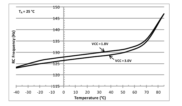
Figure 4. Calibrated RC Oscillator Typical Frequency Variation vs. Temperature
Figure 5 shows the typical uncalibrated RC oscillator frequency variation vs. temperature.
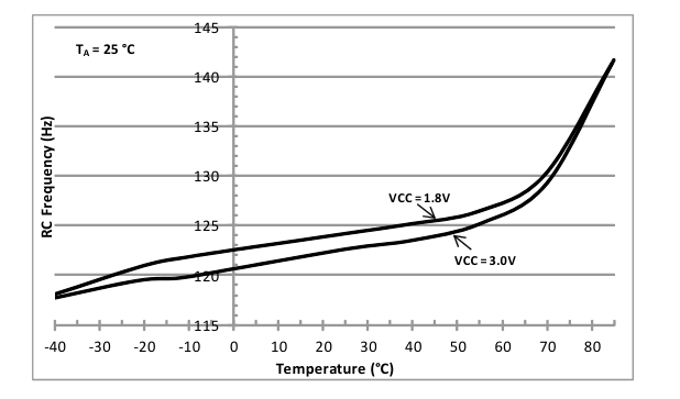
Figure 5. Uncalibrated RC Oscillator Typical Frequency Variation vs. Temperature
Page 14
| AB08X5 Real-Time Clock Family | ||
| Date of Issue: October 16, 2014 | 3.0 x 3.0 mm | |
| Page 14 of 33 | Abracon Drawing #453567 | Revision: C |
5.5 VCC Supply Current
Table 8 lists the current supplied into the VCC power input under various conditions.
TYP values at 25 °C, MAX values at 85 °C, VCC Power state
For Table 8, TA = -40 °C to 85 °C, VBAT = 0 V to 3.6 V
Table 8: VCC Supply Current
| SYMBOL | PARAMETER | TEST CONDITIONS | VCC | MIN | TYP | MAX | UNIT |
|---|---|---|---|---|---|---|---|
| I VCC:I2C | V supply current during I2C CC burst read/write | 400kHz bus speed, 2.2k pull-up resistors on SCL/SDA(1) | 3.0V | 6 | 10 | µA | |
| 1.8V | 1.5 | 3 | |||||
| I VCC:SPIW | V supply current during SPI CC burst write | 2 MHz bus speed (2) | 3.0V | 8 | 12 | µA | |
| 1.8V | 4 | 6 | |||||
| I VCC:SPIR | V supply current during SPI CC burst read | 2 MHz bus speed (2) | 3.0V | 23 | 37 | µA | |
| 1.8V | 13 | 21 | |||||
| I VCC:XT | V supply current in XT oscil- CC lator mode | Time keeping mode with XT oscillator running(3) | 3.0V | 55 | 330 | nA | |
| 1.8V | 51 | 290 | |||||
| I VCC:RC | V supply current in RC oscil- CC lator mode | Time keeping mode with only the RC oscillator running (XT oscillator is off)(3) | 3.0V | 14 | 220 | nA | |
| 1.8V | 11 | 170 | |||||
| I VCC:ACAL | Average V supply current in CC Autocalibrated RC oscillator mode | Time keeping mode with only RC oscillator running and Auto- calibration enabled. ACP = 512 seconds(3) | 3.0V | 22 | 235 | nA | |
| 1.8V | 18 | 190 | |||||
| (1) Excluding external peripherals and pull-up resistor current. All other inputs (besides SDA and SCL) are at 0V or V . CC AB0805 only. Test conditions: Continuous burst read/write, 0x55 data pattern, 25 s between each data byte, 20 pF load on each bus pin. (2) Excluding external peripheral current. All other inputs (besides SDI, nCE and SCL) are at 0V or V . AB0815 only. Test CC conditions: Continuous burst write, 0x55 data pattern, 25 s between each data byte, 20 pF load on each bus pin. (3) All inputs and outputs are at 0 V or V CC | |||||||
Page 15
| AB08X5 Real-Time Clock Family | ||
| Date of Issue: October 16, 2014 | 3.0 x 3.0 mm | |
| Page 15 of 33 | Abracon Drawing #453567 | Revision: C |
Figure 6 shows the typical VCC power state operating current vs. temperature in XT mode.
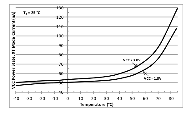
Figure 6. Typical VCC Current vs. Temperature in XT Mode
Figure 7 shows the typical VCC power state operating current vs. temperature in RC mode.
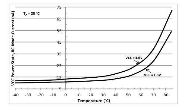
Figure 7. Typical VCC Current vs. Temperature in RC Mode
Page 16
| AB08X5 Real-Time Clock Family | ||
| Date of Issue: October 16, 2014 | 3.0 x 3.0 mm | |
| Page 16 of 33 | Abracon Drawing #453567 | Revision: C |
Figure 8 shows the typical VCC power state operating current vs. temperature in RC Autocalibration mode.
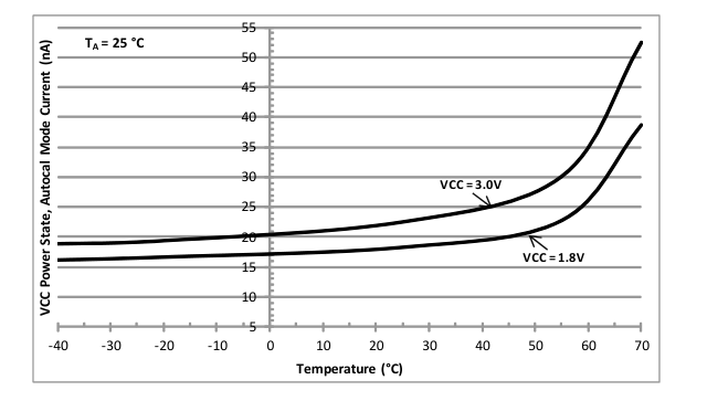
Figure 8. Typical VCC Current vs. Temperature in RC Autocalibration Mode
Figure 9 shows the typical VCC power state operating current vs. voltage for XT Oscillator and RC Oscillator modes and the average current in RC Autocalibrated mode.
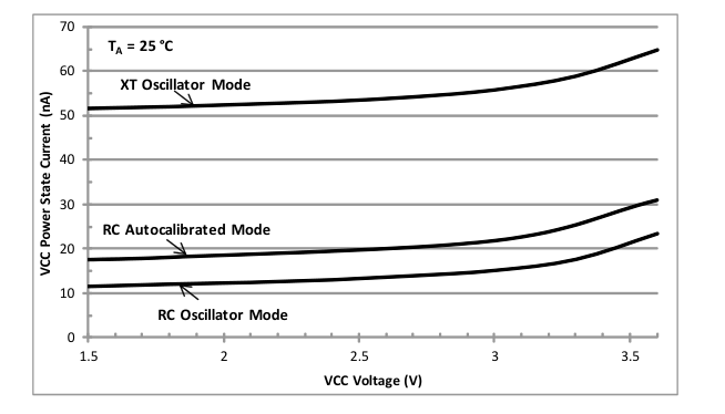
Figure 9. Typical VCC Current vs. Voltage, Different Modes of Operation
Page 17
| AB08X5 Real-Time Clock Family | ||
| Date of Issue: October 16, 2014 | 3.0 x 3.0 mm | |
| Page 17 of 33 | Abracon Drawing #453567 | Revision: C |
Figure 10 shows the typical VCC power state operating current during continuous I2C and SPI burst read and write activity. Test conditions: TA = 25 °C, 0x55 data pattern, 25 s between each data byte, 20 pF load on each bus pin, pull-up resistor current not included.
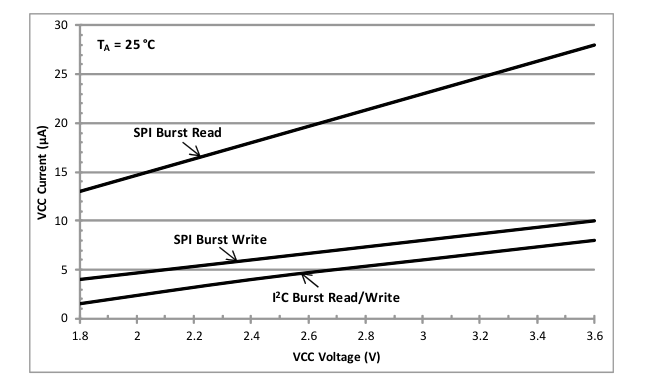
Figure 10. Typical VCC Current vs. Voltage, I²C and SPI Burst Read/Write
Page 18
| AB08X5 Real-Time Clock Family | ||
| Date of Issue: October 16, 2014 | 3.0 x 3.0 mm | |
| Page 18 of 33 | Abracon Drawing #453567 | Revision: C |
5.6 VBAT Supply Current
Table 9 lists the current supplied into the VBAT power input under various conditions.
For Table 9, TA = -40 °C to 85 °C, TYP values at 25 °C, MAX values at 85 °C, VBAT Power state.
Table 9: VBAT Supply Current
| SYMBOL | PARAMETER | TEST CONDITIONS | V CC | V BAT | MIN | TYP | MAX | UNIT |
|---|---|---|---|---|---|---|---|---|
| I VBAT:XT | VBAT supply current in XT oscillator mode | Time keeping mode with XT oscillator running(1) | < V CCSWF | 3.0V | 56 | 330 | nA | |
| 1.8V | 52 | 290 | ||||||
| I VBAT:RC | VBAT supply current in RC oscillator mode | Time keeping mode with only the RC oscillator run- ning (XT oscillator is off)(1) | < V CCSWF | 3.0V | 16 | 220 | nA | |
| 1.8V | 12 | 170 | ||||||
| I VBAT:ACAL | Average VBAT supply current in Autocalibrated RC oscillator mode | Time keeping mode with the RC oscillator running. Autocalibration enabled. ACP = 512 seconds(1) | < V CCSWF | 3.0V | 24 | 235 | nA | |
| 1.8V | 20 | 190 | ||||||
| I VBAT:VCC | VBAT supply current in VCC powered mode | V powered mode(1) CC | 1.7 - 3.6 V | 3.0V | -5 | 0.6 | 20 | nA |
| 1.8V | -10 | 0.5 | 16 | |||||
| (1) Test conditions: All inputs and outputs are at 0 V or V . CC | ||||||||
Figure 11 shows the typical VBAT power state operating current vs. temperature in XT mode.
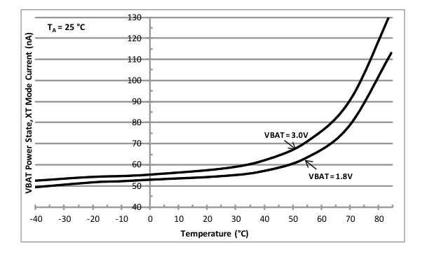
Figure 11. Typical VBAT Current vs. Temperature in XT Mode
Page 19
| AB08X5 Real-Time Clock Family | ||
| Date of Issue: October 16, 2014 | 3.0 x 3.0 mm | |
| Page 19 of 33 | Abracon Drawing #453567 | Revision: C |
Figure 12 shows the typical VBAT power state operating current vs. temperature in RC mode.
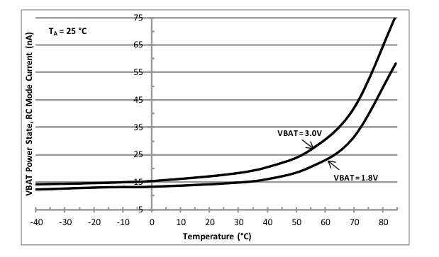
Figure 12. Typical VBAT Current vs. Temperature in RC Mode
Figure 13 shows the typical VBAT power state operating current vs. temperature in RC Autocalibration mode.
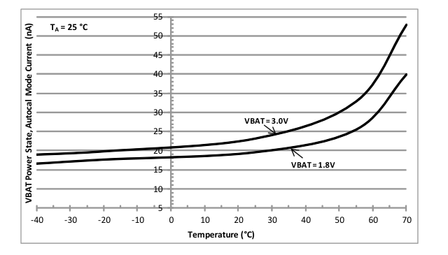
Figure 13. Typical VBAT Current vs. Temperature in RC Autocalibration Mode
Page 20
| AB08X5 Real-Time Clock Family | ||
| Date of Issue: October 16, 2014 | 3.0 x 3.0 mm | |
| Page 20 of 33 | Abracon Drawing #453567 | Revision: C |
Figure 14 shows the typical VBAT power state operating current vs. voltage for XT Oscillator and RC Oscillator modes and the average current in RC Autocalibrated mode, VCC = 0 V.
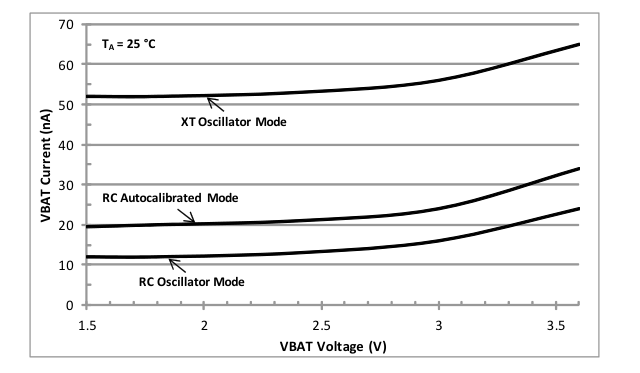
Figure 14. Typical VBAT Current vs. Voltage, Different Modes of Operation
Figure 15 shows the typical VBAT current when operating in the VCC power state, VCC = 1.7 V.
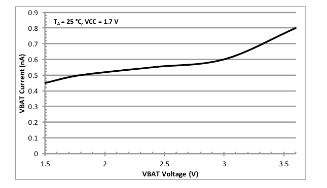
Figure 15. Typical VBAT Current vs. Voltage in VCC Power State
Page 21
| AB08X5 Real-Time Clock Family | ||
| Date of Issue: October 16, 2014 | 3.0 x 3.0 mm | |
| Page 21 of 33 | Abracon Drawing #453567 | Revision: C |
5.7 BREF Electrical Characteristics
Table 10 lists the parameters of the VBAT voltage thresholds. BREF values other than those listed in the table are not supported.
For Table 10, TA = -20 °C to 70 °C, TYP values at 25 °C, VCC = 1.7 to 3.6V.
Table 10: BREF Parameters
| SYMBOL | PARAMETER | BREF | MIN | TYP | MAX | UNIT |
|---|---|---|---|---|---|---|
| V BRF | VBAT falling threshold | 0111 | 2.3 | 2.5 | 3.3 | V |
| 1011 | 1.9 | 2.1 | 2.8 | |||
| 1101 | 1.6 | 1.8 | 2.5 | |||
| 1111 | 1.4 | |||||
| V BRR | VBAT rising threshold | 0111 | 2.6 | 3.0 | 3.4 | V |
| 1011 | 2.1 | 2.5 | 2.9 | |||
| 1101 | 1.9 | 2.2 | 2.7 | |||
| 1111 | 1.6 | |||||
| V BRH | VBAT threshold hysteresis | 0111 | 0.5 | V | ||
| 1011 | 0.4 | |||||
| 1101 | 0.4 | |||||
| 1111 | 0.2 | |||||
| T BR | VBAT analog comparator recom- mended operating temperature range | All values | -20 | 70 | °C |
Page 22
| AB08X5 Real-Time Clock Family | ||
| Date of Issue: October 16, 2014 | 3.0 x 3.0 mm | |
| Page 22 of 33 | Abracon Drawing #453567 | Revision: C |
5.8 I²C AC Electrical Characteristics
Figure 16 and Table 11 describe the I2C AC electrical parameters.
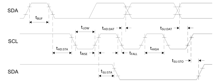
Figure 16. I²C AC Parameter Definitions
For Table 11, TA = -40 °C to 85 °C, TYP values at 25 °C.
Table 11: I²C AC Electrical Parameters
| SYMBOL | PARAMETER | VCC | MIN | TYP | MAX | UNIT |
|---|---|---|---|---|---|---|
| f SCL | SCL input clock frequency | 1.7V-3.6V | 10 | 400 | kHz | |
| t LOW | Low period of SCL clock | 1.7V-3.6V | 1.3 | µs | ||
| t HIGH | High period of SCL clock | 1.7V-3.6V | 600 | ns | ||
| t RISE | Rise time of SDA and SCL | 1.7V-3.6V | 300 | ns | ||
| t FALL | Fall time of SDA and SCL | 1.7V-3.6V | 300 | ns | ||
| t HD:STA | START condition hold time | 1.7V-3.6V | 600 | ns | ||
| t SU:STA | START condition setup time | 1.7V-3.6V | 600 | ns | ||
| t SU:DAT | SDA setup time | 1.7V-3.6V | 100 | ns | ||
| t HD:DAT | SDA hold time | 1.7V-3.6V | 0 | ns | ||
| t SU:STO | STOP condition setup time | 1.7V-3.6V | 600 | ns | ||
| t BUF | Bus free time before a new transmission | 1.7V-3.6V | 1.3 | µs |
Page 23
| AB08X5 Real-Time Clock Family | ||
| Date of Issue: October 16, 2014 | 3.0 x 3.0 mm | |
| Page 23 of 33 | Abracon Drawing #453567 | Revision: C |
5.9 SPI AC Electrical Characteristics
Figure 17, Figure 18, and Table 12 describe the SPI AC electrical parameters.
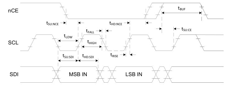
Figure 17. SPI AC Parameter Definitions – Input
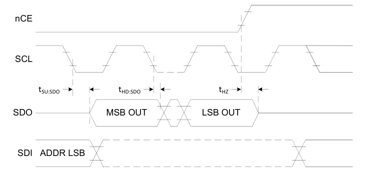
Figure 18. SPI AC Parameter Definitions – Output
For Table 12, TA = -40 °C to 85 °C, TYP values at 25 °C.
Page 24
| AB08X5 Real-Time Clock Family | ||
| Date of Issue: October 16, 2014 | 3.0 x 3.0 mm | |
| Page 24 of 33 | Abracon Drawing #453567 | Revision: C |
Table 12: SPI AC Electrical Parameters
| SYMBOL | PARAMETER | VCC | MIN | TYP | MAX | UNIT |
|---|---|---|---|---|---|---|
| f SCL | SCL input clock frequency | 1.7V–3.6V | 0.01 | 2 | MHz | |
| t LOW | Low period of SCL clock | 1.7V–3.6V | 200 | ns | ||
| t HIGH | High period of SCL clock | 1.7V–3.6V | 200 | ns | ||
| t RISE | Rise time of all signals | 1.7V–3.6V | 1 | µs | ||
| t FALL | Fall time of all signals | 1.7V–3.6V | 1 | µs | ||
| t SU:NCE | nCE low setup time to SCL | 1.7V–3.6V | 200 | ns | ||
| t HD:NCE | nCE hold time to SCL | 1.7V–3.6V | 200 | ns | ||
| t SU:CE | nCE high setup time to SCL | 1.7V–3.6V | 200 | ns | ||
| t SU:SDI | SDI setup time | 1.7V–3.6V | 40 | ns | ||
| t HD:SDI | SDI hold time | 1.7V–3.6V | 50 | ns | ||
| t SU:SDO | SDO output delay from SCL | 1.7V–3.6V | 150 | ns | ||
| t HD:SDO | SDO output hold from SCL | 1.7V–3.6V | 0 | ns | ||
| t HZ | SDO output Hi-Z from nCE | 1.7V–3.6V | 250 | ns | ||
| t BUF | nCE high time before a new transmission | 1.7V–3.6V | 200 | ns |
Page 25
| AB08X5 Real-Time Clock Family | ||
| Date of Issue: October 16, 2014 | 3.0 x 3.0 mm | |
| Page 25 of 33 | Abracon Drawing #453567 | Revision: C |
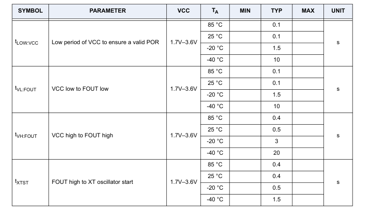
5.10 Power On AC Electrical Characteristics
Figure 19 and Table 13 describe the power on AC electrical characteristics for the FOUT pin and XT oscillator.
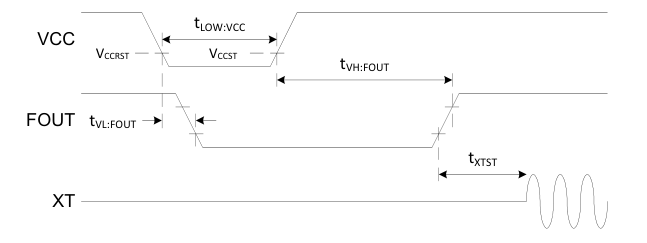
Figure 19. Power On AC Electrical Characteristics
For Table 13, TA = -40 °C to 85 °C, VBAT < 1.2 V
Table 13: Power On AC Electrical Parameters
Page 26
| AB08X5 Real-Time Clock Family | ||
| Date of Issue: October 16, 2014 | 3.0 x 3.0 mm | |
| Page 26 of 33 | Abracon Drawing #453567 | Revision: C |
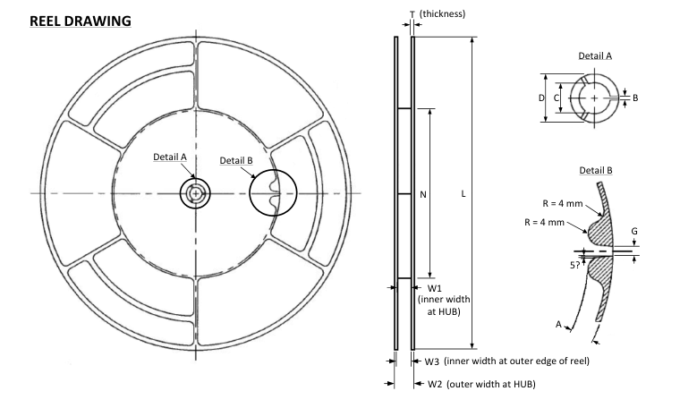
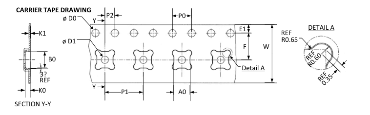
6. Tape and Reel Information
Page 27
| AB08X5 Real-Time Clock Family | ||
| Date of Issue: October 16, 2014 | 3.0 x 3.0 mm | |
| Page 27 of 33 | Abracon Drawing #453567 | Revision: C |
Table 14: Tape and Reel Dimensions
| 330 x 178 x 12 mm Reel Dimensions | 3x3 QFN Carrier Tape Dimensions | ||||||||
| Symbol | MIN | TYP | MAX | Units | Symbol | MIN | TYP | MAX | Units |
| T | 2.3 | 2.5 | 2.7 | mm | B0 | 3.2 | 3.3 | 3.4 | mm |
| N | 178.0 | K0 | 0.9 | 1.0 | 1.1 | ||||
| L | 330.0 | K1 | 0.25 | 0.3 | 0.35 | ||||
| W1 | 12.4 | 12.4 | 12.6 | D0 | 1.50 | 1.55 | 1.60 | ||
| W2 | 18.4 | D1 | 1.5 | ||||||
| W3 | 12.4 | 15.4 | P0 | 3.9 | 4.0 | 4.1 | |||
| C | 12.8 | 13.0 | 13.5 | P1 | 7.9 | 8.0 | 8.1 | ||
| D | 20.2 | P2 | 1.9 | 2.0 | 2.1 | ||||
| A | 10.0 | A0 | 3.2 | 3.3 | 3.4 | ||||
| G | 4.0 | E1 | 1.65 | 1.75 | 1.85 | ||||
| B | 1.5 | F | 5.4 | 5.5 | 5.6 | ||||
| W | 11.7 | 12.0 | 12.3 | ||||||
Page 28
| AB08X5 Real-Time Clock Family | ||
| Date of Issue: October 16, 2014 | 3.0 x 3.0 mm | |
| Page 28 of 33 | Abracon Drawing #453567 | Revision: C |
7. Reflow Profile
Figure 20 illustrates the reflow soldering requirements.
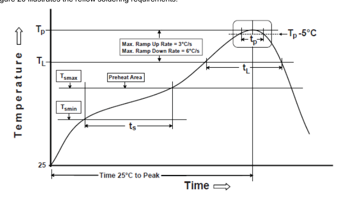
Figure 20. Reflow Soldering Diagram
Table 15: Reflow Soldering Requirements (Pb-free assembly)
| Profile Feature | Requirement |
| Preheat/Soak Temperature Min (T ) smin Temperature Max (T ) smax Time (ts) from (T to T ) smin smax | 150 °C 200 °C 60-120 seconds |
| Ramp-up rate (T to Tp) L | 3 °C/second max. |
| Liquidous temperature (T ) L Time (t ) maintained above T L L | 217 °C 60-150 seconds |
| Peak package body temperature (T ) p | 260 °C max. |
| Time (t ) within 5 °C of T p p | 30 seconds max. |
| Ramp-down rate (T to T ) p L | 6 °C/second max. |
| Time 25 °C to peak temperature | 8 minutes max. |
Page 29
| AB08X5 Real-Time Clock Family | ||
| Date of Issue: October 16, 2014 | 3.0 x 3.0 mm | |
| Page 29 of 33 | Abracon Drawing #453567 | Revision: C |
8. Ordering Information
Table 16: Ordering Information
| AB08X5 Orderable Part Numbers | Package | Temperature Range | MSL Level(2) | |
|---|---|---|---|---|
| P/N | Tape and Reel Qty | |||
| AB0805-T3 | 3000pcs/reel | Pb-Free(1) 16-Pin QFN 3 x 3 mm | -40 to +85 °C | 1 |
| AB0815-T3 | 3000pcs/reel | |||
| (1) Compliant and certified with the current RoHS requirements for all 6 substances, including the requirement that lead not exceed 0.1% by weight in raw homogeneous materials. The package was designed to be soldered at high temperatures (per reflow profile) and can be used in specified lead-free processes. (2) Moisture Sensitivity Level rating according to the JEDEC J-STD-020D.1 industry standard classifications. | ||||
Page 30
| AB08X5 Real-Time Clock Family | ||
| Date of Issue: October 16, 2014 | 3.0 x 3.0 mm | |
| Page 30 of 33 | Abracon Drawing #453567 | Revision: C |
9. Notes
i. The parts are manufactured in accordance with this specification. If other conditions and specifications which are required for this specification, please contact ABRACON for more information. ii. ABRACON will supply the parts in accordance with this specification unless we receive a written request to modify prior to an order placement. iii. In no case shall ABRACON be liable for any product failure from inappropriate handling or operation of the item beyond the scope of this specification. iv. When changing your production process, please notify ABRACON immediately. v. ABRACON Corporation’s products are COTS – Commercial-Off-The-Shelf products; suitable for
Commercial, Industrial and, where designated, Automotive Applications. ABRACON’s products are not specifically designed for Military, Aviation, Aerospace, Life-dependant Medical applications or any application requiring high reliability where component failure could result in loss of life and/or property. For applications requiring high reliability and/or presenting an extreme operating environment, written consent and authorization from ABRACON Corporation is required. Please contact ABRACON Corporation for more information. vi. All specifications and Marking will be subject to change without notice.
Page 31
| AB08X5 Real-Time Clock Family | ||
| Date of Issue: October 16, 2014 | 3.0 x 3.0 mm | |
| Page 31 of 33 | Abracon Drawing #453567 | Revision: C |
10. ABRACON CORPORATION – TERMS & CONDITIONS OF SALE
The following are the terms and conditions under which Abracon Corporation (“AB”) agrees to sell, to the entity named on the face hereof (“Buyer”), the products specified on the face hereof (the “Products”). Notwithstanding Buyer’s desire to use standardized RFQs, purchase order forms, order forms, acknowledgment forms and other documents which may contain terms in addition to or at variance with these terms, it is expressly understood and agreed that other forms shall neither add to, nor vary, these terms whether or not these terms are referenced therein. Buyer may assent to these terms by written acknowledgment, implication and/or by acceptance or payment of goods ordered any of which will
constitute assent.
- Prices: Prices shown on the face hereof are in US dollars, with delivery terms specified herein and are exclusive of any other charges including, without limitation, fees for export, special packaging, freight, insurance and similar charges. AB reserves the right to increase the price of Products by written notice to Buyer at least thirty (30) days prior to the original date of shipment. When quantity price discounts are quoted by AB, the discounts are computed separately for each type of product to be sold and are based upon the quantity of each type and each size ordered at any one time. If any discounted order is reduced by Buyer with AB’s consent, the prices shall be adjusted to the higher prices,
if applicable, for the remaining order. 2. Taxes: Unless otherwise specified in the quotation, the prices do not include any taxes, import or export duties, tariffs, customs charges or any such other levies. Buyer agrees to reimburse AB the amount of any federal, state, county, municipal, or other taxes, duties, tariffs, or custom charges AB is required to pay. If Buyer is exempt from any such charges, Buyer must provide AB with appropriate documentation. 3. Payment Terms: For each shipment, AB will invoice Buyer for the price of the Products plus all applicable taxes, packaging, transportation, insurance and other charges. Unless otherwise stated in a
separate agreement or in AB’s quotation, payments are due within thirty (30) days from the date of invoice, subject to AB’s approval of Buyer’s credit application. All invoicing disputes must be submitted in writing to AB within ten (10) days of the receipt of the invoice accompanied by a reasonably detailed explanation of the dispute. Payment of the undisputed amounts shall be made timely. AB reserves the right to require payment in advance or C.O.D. and otherwise modified credit terms. When partial shipments are made, payments for such shipments shall become due in accordance with the above terms upon submission of invoices. If, at the request of Buyer, shipment is postponed
for more than thirty (30) days, payment will become due thirty days after notice to Buyer that Products are ready for shipment. Any unpaid due amounts will be subject to interest at one decimal five percent (1.5%) per month, or, if less, the maximum rate allowed by law. 4. Delivery and Shipment: Shipment dates are estimates only. Failure to deliver by a specified date shall neither entitle Buyer to any compensation nor impose any liability on AB. AB reserves the right to ship and bill ten percent more or less than the exact quantity specified on the face hereof. All shipments will be made Ex Works as per Incoterms 2000 from AB’s place of shipment. In the absence of
specific instructions, AB will select the carrier. Claims against AB for shortages must be made in writing within ten (10) days after the arrival of the shipment. AB is not required to notify Buyer of the shipment. Buyer shall pay all freight charges, insurance and other shipping expenses. Freight charges, insurance and other shipping expenses itemized in advance of actual shipment, if any, are estimates only that are calculated on the basis of standard tariffs and may not reflect actual costs. Buyer must pay actual costs. 5. Purchase Order Changes and Cancellations: Purchase orders for standard AB Products may not be canceled within sixty (60) days of the original shipping date. Purchase orders for non-standard AB
Products are non-cancelable and non-returnable. All schedule changes must be requested at least thirty (30) days prior to original shipping date. Maximum schedule change “push-out” shall be no more than thirty (30) days from original shipping date. AB may terminate or cancel this order, in whole or in part, at any time prior to the completion of performance by written notice to Buyer without incur-
Page 32
| AB08X5 Real-Time Clock Family | ||
| Date of Issue: October 16, 2014 | 3.0 x 3.0 mm | |
| Page 32 of 33 | Abracon Drawing #453567 | Revision: C |
ring any liability to Buyer for breach of contract or otherwise. AB reserves the right to allocate Products in its sole discretion among Buyer and other potential buyers, or defer or delay the shipment of any Product, which is in short supply due to any reason. 6. Title and Risk of Loss: AB’s responsibility for any loss or damage ends, and title passes, when Products are delivered Ex Works as per Incoterms 2000 at AB’s designated shipping location to carrier, to Buyer or to Buyer’s agent, whichever occurs first. 7. Packing: Packaging shall be AB’s standard shipping materials or as specified on the face hereof. Any cost of non-standard packaging and handling requested by Buyer shall be abided by AB provided
Buyer gives reasonable prior notice and agrees in writing to pay additional costs. 8. Security Interest: Buyer hereby grants AB a purchase money security interest in the Products sold and in the proceeds of resale of such Products until such time as Buyer has paid all charges. AB retains all right and remedies available to AB under the Uniform Commercial Code. 9. Specifications: Specifications for each Product are the specifications specified in the published datasheets of such Product, as of the date of AB’s quotation (the “Specifications”). Except as otherwise agreed, AB reserves the right to modify the Specifications at any time without adversely affecting the
functionality. 10. Acceptance: Unless Buyer notifies AB in writing within ten (10) days from the date of receipt of Products that the Products fail to conform to the Specifications, the Products will be deemed accepted by Buyer. No such claim of non-conformity shall be valid if (i) the Products have been altered, modified or damaged by Buyer, (ii) the rejection notice fails to explain the non-conformance in reasonable detail and is not accompanied by a test report evidencing the non-conformity, or (iii) rejected Products are not returned to AB within thirty (30) days of rejection; provided, that no Product returns may be made without a return material authorization issued by AB.
- Limited Warranties and Disclaimers: AB warrants to Buyer that each Product, for a period of twelve (12) months from shipment date thereof, will conform to the Specifications and be free from defects in materials and workmanship. AB’s sole liability and Buyer’s exclusive remedy for Products that fail to conform to this limited warranty (“Defective Products”) is limited to repair or replacement of such Defective Products, or issue a credit or rebate of no more than the purchase price of such Defective Products, at AB’s sole option and election. This warranty shall not apply: (i) if Products have been damaged or submitted to abnormal conditions (mechanical, electrical, or thermal) during transit, stor-
age, installation, or use; or (ii) if Products are subject to Improper Use (as defined below); or (iii) if the non-conformance of Products results from misuse, neglect, improper testing, storage, installation, unauthorized repair, alteration, or excess usage at or beyond the maximum values (temperature limit, maximum voltage, and other Specification limits) defined by AB; (iv) to any other default not attributable to AB; or (v) removal, alteration, or tampering of the original AB product labeling. This warranty does not extend to Products or components purchased from entities other than AB or AB’s authorized distributors or to third-party software or documentation that may be supplied with any Product. In the
event no defect or breach of warranty is discovered by AB upon receipt of any returned Product, such Product will be returned to Buyer at Buyer’s expense and Buyer will reimburse AB for the transportation charges, labor, and associated charges incurred in testing the allegedly Defective Product. The above warranty is for Buyer’s benefit only, and is non-transferable. OTHER THAN THE LIMITED WARRANTY SET FORTH ABOVE, AB MAKES NO WARRANTIES, EXPRESS, STATUTORY, IMPLIED, OR OTHERWISE AND SPECIFICALLY DISCLAIMS THE IMPLIED WARRANTIES OF MERCHANTABILITY, FITNESS FOR A PARTICULAR PURPOSE AND NON-INFRINGEMENT, TO THE MAXIMUM EXTENT PERMITTED BY LAW. WITHOUT LIMITING THE GENERALITY OF THE
FOREGOING DISCLAIMERS, AB INCORPORATES BY REFERENCE ANY PRODUCT-SPECIFIC WARRANTY DISCLAIMERS SET FORTH IN THE PUBLISHED PRODUCT DATASHEETS. 12. Limitation of Liability: AB SHALL HAVE NO LIABILITY FOR LOSS ARISING FROM ANY CLAIM MADE AGAINST BUYER, OR FOR SPECIAL, INDIRECT, RELIANCE, INCIDENTAL, CONSEQUEN- TIAL, OR PUNITIVE DAMAGES INCLUDING, WITHOUT LIMITATION, LOSS OF USE, PROFITS, REVENUES, OR COST OF PROCUREMENT OF SUBSTITUTE GOODS BASED ON ANY BREACH
Page 33
| AB08X5 Real-Time Clock Family | ||
| Date of Issue: October 16, 2014 | 3.0 x 3.0 mm | |
| Page 33 of 33 | Abracon Drawing #453567 | Revision: C |
OR DEFAULT OF AB, HOWEVER CAUSED, AND UNDER ANY THEORY OF LIABILITY. BUYER’S SOLE REMEDY AND AB’S SOLE AND TOTAL LIABILITY FOR ANY CAUSE OF ACTION, WHETHER IN CONTRACT (INCLUDING BREACH OF WARRANTY) OR TORT (INCLUDING NEG- LIGENCE OR MISREPRESENTATION) OR UNDER STATUTE OR OTHERWISE SHALL BE LIM- ITED TO AND SHALL NOT EXCEED THE AGGREGATE AMOUNTS PAID BY BUYER TO AB FOR PRODUCTS WHICH GIVE RISE TO CLAIMS. BUYER SHALL ALWAYS INFORM AB OF ANY BREACH AND AFFORD AB REASONABLE OPPORTUNITY TO CORRECT ANY BREACH. THE FOREGOING LIMITATIONS SHALL APPLY REGARDLESS OF WHETHER AB HAS BEEN ADVISED OF THE POSSIBILITY OF SUCH DAMAGES AND NOTWITHSTANDING THE FAILURE OF ESSENTIAL PURPOSE OF ANY LIMITED REMEDY.
- Improper Use: Buyer agrees and covenants that, without AB’s prior written approval, Products will not be used in life support systems, human implantation, nuclear facilities or systems or any other application where Product failure could lead to loss of life or catastrophic property damage (each such use being an “Improper Use”). Buyer will indemnify and hold AB harmless from any loss, cost, or damage resulting from Improper Use of the Products. 14. Miscellaneous: In the event of any insolvency or inability to pay debts as they become due by Buyer, or voluntary or involuntary bankruptcy proceeding by or against Buyer, or appointment of a receiver or
assignee for the benefit of creditors of Buyer, AB may elect to cancel any unfulfilled obligations. No Products or underlying information or technology may be exported or re-exported, directly or indirectly, contrary to US law or US Government export controls. AB will be excused from any obligation to the extent performance thereof is caused by, or arises in connection with, acts of God, fire, flood, riots, material shortages, strikes, governmental acts, disasters, earthquakes, inability to obtain labor or materials through its regular sources, delay in delivery by AB’s supplies or any other reason beyond the reasonable control of AB. In the event any one or more of the provisions contained herein shall for
any reason be held to be invalid, illegal, or unenforceable in any respect, such invalidity, illegality, or unenforceability shall not affect any other provision hereof and these terms shall be construed as if such invalid, illegal, or unenforceable provision had never been contained herein. A waiver of a breach or default under these terms shall not be a waiver of any subsequent default. Failure of AB to enforce compliance with any of these terms shall not constitute a waiver of such terms. These terms are governed by the laws of the State of California without reference to conflict of law principles. The federal and state courts located within the State of California will have exclusive jurisdiction to adjudi-
cate any dispute arising out of these terms.