
DATASHEET SEARCH SITE
Document overview
- Manufacturer or author: Provided By www.digicamel.com(FREE DATASHEET DOWNLOAD SITE)
- PDF pages: 24
Technical content
Description
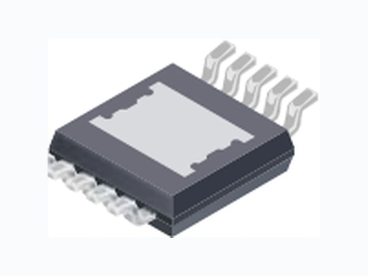
The A8513 is a single-output white LED (WLED) driver for LCD backlighting. It integrates a current-mode boost converter with an internal power switch and one current sink. The A8513 can operate from a single power supply from 4.5 to 40 V , to accommodate start/stop, cold crank, and load dump requirements. A 2 MHz boost converter switching frequency allows the A8513 to operate above the AM radio band. If required, the fault flag can be used as part of a circuit to drive an external P-FET to disconnect the input supply from the system in the event of a fault. The A8513 provides protection against output short and overvoltage, open or shorted diode, open or shorted LED pin, shorted boost switch or inductor, shorted I SET resistor, and IC overtemperature. A dual level cycle-by- cycle current limit function provides soft start and protects the internal current switch against high current overloads. The A8513 is provided in a 10-pin MSOP package (suffix LY) and a 16-pin TSSOP package (suffix LP). Both packages have an exposed thermal pad for enhanced thermal dissipation, and are lead (Pb) free, with 100% matte tin leadframe plating. A8513-DS Rev. 2 Features and Benefits
- AEC-Q100 Qualified
- Wide input voltage range of 4.5 to 40 V for start/stop, cold crank and load dump requirements
- Boost converter switching frequency up to 2 MHz, allowing operation above the AM band
- Excellent input voltage transient response
- Internal secondary OVP for redundant protection
- Fully integrated LED current sink and boost converter with
60 V DMOS FET
- Maximum LED current of 150 mA
- Drives up to 14 series LEDs
- Single EN/PWM pin interface for PWM Dimming and Enable function
- 5000:1 PWM dimming at 200 Hz Wide Input Voltage Range, High Efficiency Fault Tolerant LED Driver Packages: Typical Application Circuit Not to scale A8513 Continued on the next page… 10-pin MSOP with exposed thermal pad (LY package) 16-pin TSSOP with exposed thermal pad (LP package) Applications:
- LCD backlighting for: ▫ Automotive infotainment ▫ Automotive cluster ▫ Automotive center stack ▫ Industrial LCD displays ▫ Portable DVD players ▫ Flatbed Scanners ▫ LED Lighting SW OVP VOUT ROVP1 ROVP2 VIN VDDCVDD COUT EN/PWM ISET GND COMP LED FAULT PAD A8513VC RISET CIN L1 D1 CP VIN RZ (Optional) CZ (Optional) Boost fSW (MHz) VIN (min) (V) LEDs per String (max) 0.25/0.5/1 5 14 21 01 4 281 2 26 9 25 7
Wide Input Voltage Range, High Efficiency Fault Tolerant LED DriverA8513 2Allegro MicroSystems, Inc.
115 Northeast Cutoff
Worcester, Massachusetts 01615-0036 U.S.A. Absolute Maximum Ratings* Characteristic Symbol Notes Rating Unit LED Pin V LED –0.3 to 55 V OVP Pin V OVP –0.3 to 60 V VIN and ¯F¯ ¯A ¯¯¯U ¯¯L¯ ¯T¯ Pins V IN , VFAULT -0.3 to 40 V SW Pin V SW Continuous –0.6 to 60 V t < 50 ns –1.0 V ISET Pin V ISET –0.3 to 5.5 V All Other Pins –0.3 to 7 V Operating Ambient Temperature T A Range K –40 to 125 ºC Maximum Junction Temperature T J(max) 150 ºC Storage Temperature T stg –55 to 150 ºC *Stresses beyond those listed in this table may cause permanent damage to the device. The Absolute Maximum ratings are stress ratings only, and functional operation of the device at these or any other conditions beyond those indicated in the Electrical Characteristics table is not implied. Exposure to Absolute Maximum-rated conditions for extended periods may affect device reliability. Features and Benefits (continued) Selection Guide Part Number Oscillator Frequency, fSW (MHz) Packing* Package A8513KLYTR-T 2 4000 pieces per 13-in. reel 10-pin MSOP with exposed thermal pad A8513KLYTR-1-T 1 Contact factory for availabilityA8513KLYTR-2-T 0.5 A8513KLYTR-3-T 0.25 A8513KLPTR-T 2 4000 pieces per 13-in. reel 16-pin TSSOP with exposed thermal pad A8513KLPTR-1-T 1 Contact factory for availabilityA8513KLPTR-2-T 0.5 A8513KLPTR-3-T 0.25 *Contact Allegro® for additional packing options
- Fault flag pin to alert the controller to a myriad of possible fault conditions
- Protection Features: ▫ Shorted output ▫ Open or shorted LED pin ▫ Output undervoltage and overvoltage ▫ Input undervoltage ▫ Shorted boost switch or inductor ▫ Shorted I SET resistor ▫ Open boost Schottky ▫ Overtemperature
Wide Input Voltage Range, High Efficiency Fault Tolerant LED DriverA8513 3Allegro MicroSystems, Inc. Worcester, Massachusetts 01615-0036 U.S.A. Pin-out Diagram Terminal List Table Name Number Function LP LY COMP 15 10 Output of the error amplifier and compensation node. Connect compensation network from this pin to GND for control loop compensation. ¯F¯ ¯A ¯¯¯U ¯¯L¯ ¯T¯ 64 This pin is used to indicate fault conditions. Logic low indicates that the A8513 has a fault present. GND 13,14 9 Ground. ISET 12 8 Connect the R ISET resistor between this pin and GND to set the 100% LED current level. LED 10 6 Connect the cathode of the LED string to this pin. NC 1,2,8,9,16 – No connection. OVP 4 2 This pin is used to sense an overvoltage condition. Connect a resistive divider from the VOUT node to this pin to adjust the Overvoltage Protection (OVP). PAD – – Exposed pad of the package providing enhanced thermal dissipation. This pad must be connected to the ground plane(s) of the PCB with at least 8 thermal vias, directly in the pad. EN/PWM 11 7 PWM dimming pin. Used to control LED intensity by using pulse width modulation. SW 3 1 The drain of the internal NMOS switch of the boost converter. VDD 7 5 Output of internal LDO. Connect a 0.1 μF decoupling capacitor between this pin and GND. VIN 5 3 Input power to the A8513. SW OVP VIN FAULT VDD COMP GND ISET EN/PWM LED PAD NC NC SW OVP VIN FAULT VDD NC NC COMP GND GND ISET EN/PWM LED NC PAD Thermal Characteristics*may require derating at maximum conditions, see application information Characteristic Symbol Test Conditions* Value Unit Package Thermal Resistance (Junction to Ambient) RθJA LP package On 4-layer PCB based on JEDEC standard 34 ºC/W On 2-layer PCB with 3.8 in.2 of copper area each side 43 ºC/W LY package On 4-layer PCB based on JEDEC standard 48 ºC/W On 2-layer PCB with 2.5 in.2 of copper area each side 48 ºC/W Package Thermal Resistance (Junction to Pad) RθJP 2 ºC/W *To be verified by characterization. Additional thermal information available on the Allegro® website.
Wide Input Voltage Range, High Efficiency Fault Tolerant LED DriverA8513 4Allegro MicroSystems, Inc. Worcester, Massachusetts 01615-0036 U.S.A. VDD Regulator UVLO Internal Soft Start Enable PWM Enable Short LED Detect ISET Fault LED Driver 1.235 V Ref Driver Circuit Internal VCC Internal VCC VREF Internal VCC VREF VREF ISS Thermal Shutdown ISS 100 kΩ Enable Current Sense Diode Open Sense OVP Sense Oscillator SW VIN COMP EN/PWM GND ISET OVP LED FAULT ∑ + Functional Block Diagram
Wide Input Voltage Range, High Efficiency Fault Tolerant LED DriverA8513 5Allegro MicroSystems, Inc. Worcester, Massachusetts 01615-0036 U.S.A. ELECTRICAL CHARACTERISTICS1 Valid at VIN = 16 V, TA = 25ºC, indicates specifications guaranteed through the full operating temperature range with TA = TJ = –40ºC to125 ºC, typical specifications are at TA = 25ºC; unless otherwise specified Characteristics Symbol Test Conditions Min. Typ. Max. Unit Input Voltage Specifications Operating Input Voltage Range V IN 4.5 − 40 V VIN Pin UVLO Start Threshold V UVLOrise VIN rising −− 4.35 V VIN Pin UVLO Stop Threshold V UVLOfall VIN falling −− 3.90 V VIN Pin UVLO Hysteresis V UVLOhys − 450 − mV Input Current Input Quiescent Current I Q EN/PWM = VIH , SW = 2 MHz, no load − 5 − mA Input Sleep Supply Current I QSLEEP VIN = 16 V, EN/PWM = 0 V − 11 0 μA Input logic Level (Low) V IL 5 V < VIN < 40 V −− 400 mV Input logic Level (High) V IH 5 V < VIN < 40 V 1.5 −− V EN/PWM Pull-Down Resistor R EN/PWM EN/PWM = 5 V − 100 − kΩ ¯F¯ ¯A ¯¯¯U ¯¯L¯ ¯T¯ Pin Pull-Down Voltage V FAULT IFAULT = 0.5 mA −− 0.4 V ¯F¯ ¯A ¯¯¯U ¯¯L¯ ¯T¯ Pin Leakage Current I FAULTlkg VFAULT = 5 V −− 1 μA Error Amplifier Open Loop Voltage Gain A VOL − 45 − dB Transconductance g m ΔICOMP = ±10 μA − 990 −μ A/V Source Current I EA(SRC) VCOMP = 1.5 V − –360 −μ A Sink Current I EA(SINK) VCOMP = 1.5 V − 360 −μ A COMP Pin Pull-Down Resistance R COMP ¯F¯ ¯A ¯¯¯U ¯¯L¯ ¯T¯ asserted − 2000 −Ω Output Overvoltage Protection Overvoltage Protection Threshold V OVPHI(th) Measured at OVP Pin 1.168 1.218 1.268 V OVP Pin Leakage Current I OVPH Standard CMOS input, measured at VOVP = 1.2 V −− 100 nA OVP Pin Undervoltage Threshold V UVP(th) Measured at OVP Pin −− 110 mV Secondary Overvoltage Protection V OVP(sec) Measured at SW Pin 53 55.5 58 V BOOST Switch Switch On-Resistance R DS(on)SW ISW = 750 mA, VIN = 16 V − 450 800 m Ω Switch Leakage Current I SWlkg VSW = 16 V, EN/PWM = VIL , TA = TJ between –40ºC and 85ºC − 0.1 1 uA VSW = 16 V, EN/PWM = VIL , TA = TJ = 125ºC − 10 − uA Switch Current Limit I SW(LIM) 1.9 2.2 2.8 A Secondary Switch Current Limit I SW(LIM2) Higher than ISW(LIM)(max) in all conditions, A8513 latches when detected 3 3.5 4.64 A Minimum Switch On-Time t SW(ON) − 75 100 ns Minimum Switch Off-Time t SW(OFF) − 55 85 ns Continued on the next page…
Wide Input Voltage Range, High Efficiency Fault Tolerant LED DriverA8513 6Allegro MicroSystems, Inc. Worcester, Massachusetts 01615-0036 U.S.A. Oscillator Frequency Oscillator Frequency f SW A8513KLYTR-1-T, A8513KLPTR-1-T 1.8 2 2.2 MHz A8513KLYTR-2-T, A8513KLPTR-2-T 0.9 1 1.1 MHz A8513KLYTR-3-T, A8513KLPTR-3-T 450 500 550 kHz A8513KLYTR-4-T, A8513KLPTR-4-T 225 250 275 kHz LED Current Sinks LED Accuracy Err LED ISET = 150 μA −− 3% LED Regulation Voltage V LED ISET = 150 μA − 880 − mV ISET to ILED Current Gain A ISET ISET = 150 μA 1014 1045 1076 A/A ISET Pin Voltage V ISET − 1.003 − V Allowable ISET Current I SET 40 − 160 μA Soft Start LED Current Gain A ILEDSS Current through enabled LED pin during soft start − 48 − A/A Maximum PWM Dimming Off-Time t PWML Measured while EN/PWM = low during dimming control, and internal references are powered-on (exceeding t PWML results in shutdown) − 16 − ms Minimum PWM On-Time t PWMH First cycle when powering-up A8513 − 1.5 3 μs EN/PWM High to LED-On Delay t dPWM(on) Time between PWM enable and when LED current reaches 90% of maximum; V PWM = 0 → 2 V − 250 500 ns EN/PWM Low to LED-Off Delay t dPWM(off) Time between PWM enable going low and when LED current reaches 10% of maximum; V PWM = 2 → 0 V − 250 500 ns Thermal Protection (TSD) Thermal Shutdown Threshold2 TTSD Temperature rising − 165 − ºC Thermal Shutdown Hysteresis2 T TSDHYS − 20 − ºC 1For input and output current specifications, negative current is defined as coming out of the node or pin (sourcing), and positive current is defined as going into the node or pin (sinking). 2Ensured by design and characterization, not production tested. ELECTRICAL CHARACTERISTICS1 (continued) Valid at VIN = 16 V, TA = 25ºC, indicates specifications guaranteed through the full operating temperature range with TA = TJ = –40ºC to125 ºC, typical specifications are at TA = 25ºC; unless otherwise specified Characteristics Symbol Test Conditions Min. Typ. Max. Unit
Wide Input Voltage Range, High Efficiency Fault Tolerant LED DriverA8513 7Allegro MicroSystems, Inc. Worcester, Massachusetts 01615-0036 U.S.A. Characteristic Performance -55 -5 45 145 95 -55 -5 45 145 95 -55 -5 45 145 95 -55 -5 45 145 95 4.345 4.295 4.245 4.195 4.145 4.095 4.045 3.995 3.945 3.855 3.805 3.755 3.705 3.655 3.605 3.555 3.505 VUVLOrise (V) VUVLOfall (V) VIN UVLO Rising Threshold Voltage 2.20 2.15 2.10 2.05 2.00 1.95 1.90 1.85 1.80 Switch Frequency IQSLEEP (μA) fSW (MHz) Temperature (°C) Temperature (°C) Temperature (°C) Temperature (°C) VIN Input Sleep Mode Current versus Ambient Temperature versus Ambient Temperature versus Ambient Temperature VIN UVLO Falling Threshold Voltage versus Ambient Temperature VIN = 40 V Efficiency, η (%) Input Voltage, VIN (V) Efficiency Versus Input Voltage ILED = 90 mA, LED Vf ≈ 3.2 V Efficiency Versus Input Voltage ILED = 150 mA, LED Vf ≈ 3.2 V 7856 9 1 1 1 2 1 4 10 13 15 16 17 18 19 21 20 22 Input Voltage, VIN (V) 7856 9 1 1 1 2 1 4 10 13 15 16 17 18 19 21 20 22 Efficiency, η (%) 5 series LEDs; VOUT = 17 V 6 series LEDs; VOUT = 20 V 7 series LEDs; VOUT = 23 V 5 series LEDs; VOUT = 17 V 6 series LEDs; VOUT = 20 V 7 series LEDs; VOUT = 23 V
Wide Input Voltage Range, High Efficiency Fault Tolerant LED DriverA8513 8Allegro MicroSystems, Inc. Worcester, Massachusetts 01615-0036 U.S.A. -55 -5 45 145 95 Temperature (°C) Temperature (°C) -55 -5 45 145 95 PWM dimming only PWM + analog dimming 100 0.1 0.10 151.0 150.8 150.6 150.4 150.2 150.0 149.8 149.6 LED Current Ratio (%) PWM Duty Cycle (%) Normalized LED Current Ratio versus PWM Duty Cycle fPWM = 200 Hz, VIN = 12 V, 6 series LEDs (≈ 21 V, 150 mA) LED Current versus Ambient Temperature ILED = 150 μA 0.01 0.10 1 10 100 2.5 2.4 2.3 2.2 2.1 2.0 1.9 1.8 1.7 1.6 Swtich Current, ISW (A) Switch Current Limit versus Ambient Temperature LED Current, ILED (mA)
Worcester, Massachusetts 01615-0036 U.S.A. 0.88 V at the maximum LED current). tions that would prevent the system from functioning correctly. pin is shorted to GND by pre-charging the LED pin (figure 3). OVP pin does not rise above VOVPLO(th) the IC will not power up. Figure 1. Start-up by slowly ramping up EN/PWM with VIN at 16 V; shows EN/PWM (ch4, 2 V/div.), time = 2 ms/div. Figure 2. Start-up by slowly ramping up VIN with EN/PWM at 2 V; shows EN/PWM (ch4, 2 V/div.), time = 2 ms/div. Figure 3. LED detection period; shows ¯F¯ ¯A ¯¯¯U ¯¯L¯ ¯T¯ (ch1, 5 V/div.), VLED (ch2,
10Allegro MicroSystems, Inc. Worcester, Massachusetts 01615-0036 U.S.A. LEDs are able to run at the full preset current level. where ILED is in A and RISET is in Ω. is referred to as the 100% current. pin is floated, and critical internal circuits are kept active. going low, is shown in figure 6. Figure 4. Typical PWM dimming sequence, with PWM dimming frequency Figure 5. Typical EN/PWM signal (5 V/div.) to LED current (100 mA/div.)
11Allegro MicroSystems, Inc. Worcester, Massachusetts 01615-0036 U.S.A. thus limiting the dimming ratios that can be achieved. the LED current using a single resistor connected to the ISET pin.
- For a dual-resistor configuration (lower panel of figure 7), the ISET current is controlled by the following formula: ISET = – VISET RISET VDAC – VISET (4) The advantage of this circuit is that the DAC voltage can be higher or lower, thus adjusting the LED current to a higher or lower value of the preset LED current set by the RISET resistor: ▫ VDAC = 1.003 V; the output is strictly controlled by RISET ▫ VDAC > 1.003 V; the LED current is reduced ▫ VDAC < 1.003 V; the LED current is increased Output Overvoltage Protection (OVP) and Output Undervoltage Protection (UVP) The A8513 has output overvoltage protection (OVP), output undervoltage protection and secondary overvoltage protection (open diode). Overvoltage Protection The OVP pin has a threshold, VOVPHI(th) , of 1.218 V . A resistive divider can be used to set the VOUT over- voltage protection threshold up to 45 V (see figure 8). There is no restriction on the value of the resistor chosen, but it is recom- mended that the divider current be kept between 10 and 60 μA. This will minimize the effect of sense current on the accuracy of OVP, and minimize output voltage bleed-off during PWM dim- ming. Formulas for calculating the OVP resistor voltage divider are shown below. R OVP1 = (VOVP – 1.218 V) / ISET (5) ROVP2 = 1.218 V / ISET (6) The OVP function is not inherently a latched fault. If the OVP condition occurs during a load dump, the IC will stop switching but not shut down.
Figure 7. Simplified diagram of voltage LED current control (upper) single resistor, and (lower) dual resistors. Figure 8. Simplified diagram of the OVP pin functions.
12Allegro MicroSystems, Inc. Worcester, Massachusetts 01615-0036 U.S.A. Figure 9. Open LED condition during PWM dimming. (A) The LED string Figure 10. Open LED condition when PWM duty cycle is 100%. (A) The pin). (B) The A8513 starts boosting the output voltage (ch1, 20 V/div.). Figure 11. Power-up into an open LED situation. (A) A8513 enabled, 5 V/div.), time = 1 ms/div.. Figure 12. Input disconnect switch function during an output short. (A) VOUT present due to short, before the PMOSFET (ch3, 5 V/div.) is disconnected. Figure 13. typical circuit for input disconnect switch.
13Allegro MicroSystems, Inc. Worcester, Massachusetts 01615-0036 U.S.A. Figure 14. Secondary Overvoltage protection tripped when the switching (ch2, 5 V/div.). Shows LED current (ch3, 100 mA/div.), time = 500 ns/div. Figure 15. Cycle-by-cycle current limit, inductor current is C3 (1 A/div.). Figure 16. Secondary current limit during an inductor short condition. through the inductor (C3, 2 A/div.); time = 1 μs/div.
14Allegro MicroSystems, Inc. Worcester, Massachusetts 01615-0036 U.S.A. momentary glitches on the input power supply. The VDD pin provides regulated bias supply for internal circuits. wait until EN/PWM goes high to re-enable the IC. Figure 17. Input UVLO. (A) UVLO tripped (VIN, ch1, 2 V/div.), (B) fault flag (ch4, 1 V/div.), time = 5 ms/div.
Wide Input Voltage Range, High Efficiency Fault Tolerant LED DriverA8513 15Allegro MicroSystems, Inc. Worcester, Massachusetts 01615-0036 U.S.A. Fault protection during operation The A8513 constantly monitors the state of the system to deter- mine if any fault conditions occur. The response to a triggered fault condition is summarized in the table below. Note: Some of the protection features might not be active during startup, to prevent false triggering of fault conditions. The latching faults can be cleared in two ways:
- Keep the EN/PWM pin low for more than 16 ms.
- Cycle the power to create a UVLO condition. Fault behavior diagrams are shown in figures 18, 19 and 20. Fault Mode Table Fault Name Type Active Fault Flag Set Description Boost Sink driver Primary Switch Current Protection (cycle-by-cycle current limit) Auto-restart Always No This fault condition is triggered by the cycle-by-cycle current limit ISW(LIM) . Prevents current in inductor from exceeding ISW(LIM) . Off for a single cycle On Secondary Switch Current Limit Latched Always Yes When the current through the boost switch exceeds the secondary current SW limit, ISW(LIM2) , the A8513 immediately shuts down. Off Off Secondary OVP Latched Always Yes Secondary overvoltage protection is used for open diode detection. When diode D1 opens, the switch pin voltage will increase until V OVP(sec) is reached. Off Off LED Pin Short Protection Auto-restart Startup Yes This fault prevents the A8513 from starting-up if the LED pin is shorted to ground. After the short is removed, soft-start is allowed to begin. Off Off ISET Short Protection Auto-restart Always Yes This fault occurs when the I SET current goes above 150% of the maximum Allowable ISET Current, I SET(max). The boost will stop switching and the IC will disable the LED sinks until the fault is removed. When the fault is removed, the IC tries to regulate to the preset LED current. Off Off LED String Open Protection Latched Always Yes This fault occurs when the OVP pin exceeds the V OVPHI(th) threshold. The A8513 immediately stops switching. If at the same time, the LED voltage is below regulation, the IC will shut down. Off Off Output Overvoltage Protection Auto-restart Always No This fault occurs when the OVP pin exceeds V OVPHI(th) threshold (for example, during a load dump). The A8513 immediately stops switching, but continues to sink current through the LED pin. Off On Output Undervoltage Protection Auto-restart Always Yes This fault occurs when the OVP pin senses less than 110 mV on the pin. Off Off Overtemperature Protection Auto-restart Always Yes This fault occurs when the die temperature exceeds T TSD . Off Off VIN UVLO NA Always Yes until internal regulator shuts down This fault occurs when VIN drops below VUVLOfall . This fault resets all latched faults. Off Off
16Allegro MicroSystems, Inc. Worcester, Massachusetts 01615-0036 U.S.A. Figure 18. ¯F¯ ¯A ¯¯¯U ¯¯L¯ ¯T¯ (ch1, 5 V/div.), VSW (ch2, 20 V/div.), ILED (ch3, 100 mA/div.), and ISET (ch4, 1 V/div.), time = 1 μs/div. Figure 20. VIN (ch1, 20 V/div.), VOUT (ch2, 20 V/div.), and VSW (ch3, Figure 19. ¯F¯ ¯A ¯¯¯U ¯¯L¯ ¯T¯ (ch1, 5 V/div.), ILED (ch2, 100 mA/div.), and ISET (ch3,
Wide Input Voltage Range, High Efficiency Fault Tolerant LED DriverA8513 17Allegro MicroSystems, Inc. Worcester, Massachusetts 01615-0036 U.S.A. Design Example This section provides a method for selecting component values when designing an application using the A8513. A typical circuit using this design is shown in figure 21. Assumptions: For the purposes of this example, the following are given as the application requirements:
- V IN: 5 to 16 V
- Quantity of series LEDs, #SERIESLEDS: 6
- LED current, ILED: 120 mA
- Vf at 120 mA: 3.2 V
- fSW: 2 MHz
- TA(max): 85°C
- PWM dimming frequency: 200 Hz with a minimum duty cycle of 1%. Procedure: Select the appropriate configuration and the individual component values in an ordered sequence. Step 1: Connect the series LED string from VOUT to the LED pin. Step 2: Determine the value for the ILED setting resistor, RISET : RISET = VISET × AISET/ ILED (7) = (1.003 × 1045) / 120 mA = 8.74 kΩ Choose an 8.66 kΩ resistor. Step 3: Determine the values of the OVP resistors. The OVP resistors are connected between the OVP pin and the output volt- age (VOUT) and the OVP pin and ground. Step 3a: The first step is to determine the maximum voltage based on the LED V f requirements. To this value the regulation voltage should be added, as well as another 2 V to account for noise, output ripple, and resistor tolerances. The regulation volt- age, V LED , of the A8513 is 880 mV . Then: VOUT(OVP) = #SERIESLEDS × Vf + VLED + 2 V (8) = 6 × 3.2 V+ 0.880 V + 2 V = 22.08 V To find the OVP resistor values, the user should choose a resis- tor divider that has very low current (IOVP) and ROVP should be approximately 1 MΩ. A good starting point is 50 μA as IOVP . (The IOVP current is used later in calculating the total leakage current.) Then : ROVP1 = (VOUT(OVP) – VOVPHI(th) ) / IOVP (9) = (22.08 V – 1.218 V) / 50 μA = 417.2 kΩ and: ROVP2 = VOVPHI(th) / IOVP (10) = 1.218 V / 50 μA = 24.36 kΩ Choose a value of resistor that is higher value than the calculated ROVP . In this case 422 kΩ was selected. Below is the actual value of the minimum OVP trip level with the selected resistor: VOUT(OVP) = ROVP × IOVP × VOVPHI(th) (11) = 422 kΩ × 50 μA + 1.218 V = 22.32 V STEP 3b: At this point a quick check should be done to determine if the conversion ratio is acceptable for the selected frequency: Dmaxofboost = 1 – tSW(OFF) × fSW (12) = 1 – 85 ns × 2 MHz = 83% where the Minimum Switch Off-Time, tSW(OFF) , is found in the Electrical Characteristics table. The Theoretical Maximum VOUT is then calculated as: VOUT(max) Vd=–1 – Dmaxofboost VIN(min) 5 V (13) where Vd is the diode forward voltage. The Theoretical Maximum VOUT value must be greater than the value VOUT(OVP) . If this is not the case, a lower frequency ver- sion of the A8513 should be chosen to meet the maximum duty cycle requirements. Step 4: Inductor selection. The inductor should be chosen such that it can handle the necessary input current. In most applica- tions, due to stringent EMI requirements, the system must operate in continuous conduction mode throughout the whole input volt- age range.
Wide Input Voltage Range, High Efficiency Fault Tolerant LED DriverA8513 18Allegro MicroSystems, Inc. Worcester, Massachusetts 01615-0036 U.S.A. Step 4a: Determine the Duty Cycle: D(max) Vd VIN(min) VOUT(OVP) 1 – 1 – 5 V (14) where Vd is the voltage drop of the boost diode. Step 4b: Determine the maximum and minimum input current to the system. The minimum input current will dictate the inductor value. The maximum current rating will dictate the current rating of the inductor. Given I OUT = ILED = 120 mA: IIN(max) = VIN(min) VOUT(OVP) IOUT H 0.595 A==22.32 V 5 V 0.9 120 mA (15) where η is efficiency. Next, calculate minimum input current, as follows: IIN(min) = VIN(max) VOUT(OVP) IOUT H 0.19 A== 22.32 V 16 V 0.9 120 mA (16) A good approximation of efficiency η can be taken from the effi- ciency curves located in the data sheet. A value of 90% is a good starting approximation. STEP 4c: Determine the inductor value. To assure that the inductor operates in continuous conduction mode the value of inductor should be set such that the ½ inductor ripple current is not greater than the average minimum input cur- rent. A good inductor choice for inductor ripple current is 30% of the maximum input current: ΔI L = IIN(max) × 0.3 (17) = 0.595 A × 0.3 = 0.18 A then: L = VIN(min) D(max)fSWΔIL 10.83 μH0.18 A== 0.785 V
2 MHz
(18) Double-check to make sure the ½ current ripple is less than IIN(min): IIN(min) > 1/2 ΔIL (19) 0.19 A > 0.09 A A good inductor value to use would be 10 μH. Step 4d: This step verifies that there is sufficient slope compensa- tion for the inductor chosen. The required slope compensation value for different frequencies is listed below: fSW (MHz) Slope Compensation (A/μs) 2 3.73 1 1.85 0.500 3.70 0.250 1.83 Next insert the inductor value used in the design: = VIN(min) D(max) fSWLused ΔILused 10 μH 0.20 A== 0.785 V
2.0 MHz
(20) Calculate the minimum required slope: (1 – D(max)) (1 – 0.78) fSW Required Slope (min) ΔILused 0.20 A 10 –6 11 0 –6 == 1.8 A/μs (21)
Wide Input Voltage Range, High Efficiency Fault Tolerant LED DriverA8513 19Allegro MicroSystems, Inc. Worcester, Massachusetts 01615-0036 U.S.A. For a stable system, the required minimum slope must be smaller than the IC slope compensation. Note: The slope compensation value is in A/μs; the 1×10⁻⁶ is a constant multiplier. STEP 4e: Determine the inductor current rating : ILminimum rating = IIN(max) + 1/2 ΔILused (22) = 0.595 A + 0.20 A / 2 = 0.695 A Step 5: Choose the proper switching diode. The switching diode should be chosen for three characteristics when it is used in LED lighting circuitry. The first and most obvious are the current rating of the diode and the reverse voltage rating. The reverse voltage rating should be such that during operation condition the voltage rating of the device is larger than the maximum output voltage; in this case it is V OUT (OVP) . The peak current through the diode is: Idp = IIN(max) + 1/2 ΔILused (23) = 0.595 A + 0.20 A / 2 = 0.695 A The third major component in deciding the switching diode is the reverse current, I R , characteristic of the diode. This characteristic is especially important when PWM dimming is implemented. During PWM off-time the boost converter is not switching. This results in a slow bleeding off of the output voltage, due to leakage currents. I R can be a large contributor, especially at high tempera- tures. On the diode that was selected in this design, the current varies between 1 and 100 μA. Step 6: Choose the output capacitors. The output capacitors should be chosen such that they provide filtering for both the boost converter and for the PWM dimming function. The biggest factors that contribute to the size of the output capacitor is PWM dimming frequency and the PWM duty cycle. Another major contributor is leakage current, I lkg . This current is a combination of the OVP resistor divider, IOVP , and the reverse leakage of the switching diode. In this design the PWM dimming frequency is 200 Hz and the minimum duty cycle is 1%. Typically the voltage variation on the output during PWM dimming must be less than 250 mV (V COUT) so that no audible noise can be heard. The capacitance can be calculated as follows: COUT = fPWM(dimming) 1 – Ddimming(min) 1 – 0.01 200 Hz Ilkg 120 μA 2.38 μF== 0.250 V VCOUT (24) A capacitor larger than 2.38 μF capacitor should be selected due to degradation of capacitance at high voltages on the capacitor. One ceramic 4.7 μF, 50 V capacitor is a good choice to fulfill this requirement. Corresponding capacitors include: Vendor Value Part number Murata 4.7 μF 50 V GRM32ER71H475KA88L Murata 2.2 μF 50 V GRM31CR71H225KA88L The rms current through the capacitor is given by: ICOUTrms = 1 – D(max) D(max) + ∆IL IOUT 0.120 A 0.23 A IIN(max) 1 – 0.78 0.78 + 0.20 A
0.595 A 12
(25) The output capacitor should have a current rating of at least 230 mA. The current rating of the 4.7 μF, 50V capacitor is 1.5 A.
20Allegro MicroSystems, Inc. Worcester, Massachusetts 01615-0036 U.S.A. Figure 21. A typical circuit designed using the example above in this section.
21Allegro MicroSystems, Inc. Worcester, Massachusetts 01615-0036 U.S.A. R1 is used to provide a leakage path such that the OVP pin is above 100 mV during startup. Otherwise the IC would assume the output is shorted to GND and would not proceed with soft start. R1 is used to provide a leakage path such that the OVP pin is above 100 mV during startup. Otherwise the IC would assume the output is shorted to GND and would not proceed with soft start. Figure 22. Typical application showing boost configuration and PMOS disconnect switch implementation Figure 23. Typical application showing SEPIC configuration
Wide Input Voltage Range, High Efficiency Fault Tolerant LED DriverA8513 22Allegro MicroSystems, Inc. Worcester, Massachusetts 01615-0036 U.S.A. Package LP, 16-Pin TSSOP with Exposed Thermal Pad A
1.20 MAX
0.15 0.00 0.30 0.19 0.20 0.09 0.60 ±0.15
1.00 REF
C SEATING PLANEC0.10 16X
0.65 BSC
0.25 BSC
5.00±0.10 GAUGE PLANE SEATING PLANE A Terminal #1 mark area B For Reference Only; not for tooling use (reference MO-153 ABT) Dimensions in millimeters Dimensions exclusive of mold flash, gate burrs, and dambar protrusions Exact case and lead configuration at supplier discretion within limits shown B C Exposed thermal pad (bottom surface); dimensions may vary with device 6.10 0.65 0.45 1.70 3.00 3.00 Reference land pattern layout (reference IPC7351 SOP65P640X110-17M); All pads a minimum of 0.20 mm from all adjacent pads; adjust as necessary to meet application process requirements and PCB layout tolerances; when mounting on a multilayer PCB, thermal vias at the exposed thermal pad land can improve thermal dissipation (reference EIA/JEDEC Standard JESD51-5) PCB Layout Reference View C Branded Face
3 NOM
Wide Input Voltage Range, High Efficiency Fault Tolerant LED DriverA8513 23Allegro MicroSystems, Inc. Worcester, Massachusetts 01615-0036 U.S.A. Package LY, 10-Pin MSOP with Exposed Thermal Pad Terminal #1 mark area A Gauge Plane Seating Plane 0.86 ±0.05 SEATING PLANE 0.50 REF 0.25 A B C C 0.53 ±0.10 0.15 ±0.05 0.05 0.15 0° to 6°3.00 ±0.10 1.98
1.98 MIN
1.73 0.30 0.50 1.65 0.27 0.18 For Reference Only; not for tooling use (reference JEDEC MO-187BA-T) Dimensions in millimeters Dimensions exclusive of mold flash, gate burrs, and dambar protrusions Exact case and lead configuration at supplier discretion within limits shown B Exposed thermal pad (bottom surface) Reference land pattern layout (reference IPC7351 SOP50P490X110-11M) All pads a minimum of 0.20 mm from all adjacent pads; adjust as necessary to meet application process requirements and PCB layout tolerances; when mounting on a multilayer PCB, thermal vias at the exposed thermal pad land can improve thermal dissipation (reference EIA/JEDEC Standard JESD51-5)
Wide Input Voltage Range, High Efficiency Fault Tolerant LED DriverA8513 24Allegro MicroSystems, Inc. Worcester, Massachusetts 01615-0036 U.S.A. Copyright ©2011-2012, Allegro MicroSystems, Inc. Allegro MicroSystems, Inc. reserves the right to make, from time to time, such de par tures from the detail spec i fi ca tions as may be required to per- mit improvements in the per for mance, reliability, or manufacturability of its products. Before placing an order, the user is cautioned to verify that the information being relied upon is current. Allegro’s products are not to be used in life support devices or systems, if a failure of an Allegro product can reasonably be expected to cause the failure of that life support device or system, or to affect the safety or effectiveness of that device or system. The in for ma tion in clud ed herein is believed to be ac cu rate and reliable. How ev er, Allegro MicroSystems, Inc. assumes no re spon si bil i ty for its use; nor for any in fringe ment of patents or other rights of third parties which may result from its use.
Revision History
Revision Revision Date Description of Revision Rev. 2 January 18, 2012 Update Features List