
DATASHEET SEARCH SITE
Document overview
- Manufacturer or author: Provided By www.digicamel.com(FREE DATASHEET DOWNLOAD SITE)
- PDF pages: 20
Technical content
I2 C™- Compatible Interface VPump ADD Fault Monitor OCP PNG TSD VUV EXTM VDD VS IRQ Charge Pump Oscillator Regulator Tone Detect TDO TDI VREG TDO TCAP fsw fsw 22 kHz EXTM TGate TMode 10 nF GNDLX DAC LNB Voltage Control Wave Shape Linear Stage 10 nF C13 220 nF C10 220 nF R1 R2 R3 R4 33 μH D1 220 μH BFC R5 R6 BFO BFC C12 100 7 C11 0.68 μF BFI 15 7 1 7 R10 B B B B A GND C C 100 μF 100 μF 1 μF PAD nF 100 1 MH
Description
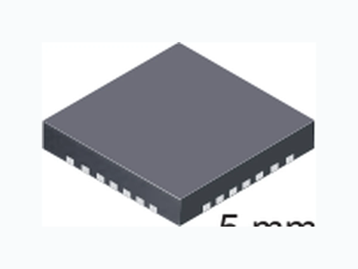
Intended for analog and digital satellite receivers, this single low noise block converter regulator (LNBR) is a monolithic linear and switching voltage regulator, specifically designed to provide the power and the interface signals to an LNB down converter via coaxial cable. The A8290 requires few external components, with the boost switch and compensation circuitry integrated inside of the device. A high switching frequency is chosen to minimize the size of the passive filtering components, further assisting in cost reduction. The high levels of component integration ensure extremely low noise and ripple figures. The A8290 has been designed for high efficiency, utilizing the Allegro ® advanced BCD process. The integrated boost switch has been optimized to minimize both switching and static losses. To further enhance efficiency, the voltage drop across the tracking regulator has been minimized. The A8290 has integrated tone detection capability, to support full two-way DiSEqC™ communications. Several schemes are available for generating tone signals, all the way down to no-load, and using either the internal clock or an external time source. A DiSEqC™ filter bypass switch is also integrated, to minimize the output impedance during tone generation. 8290-DS, Rev. 16 Features and Benefits ▪ 2-wire serial I 2C™ -compatible interface: control (write) and status (read) ▪ LNB voltages (16 programmable levels) compatible with all common standards ▪ Tracking switch-mode power converter for lowest dissipation ▪ Integrated converter switches and current sensing ▪ Output current limit of 900 mA typical, with 48 ms timer ▪ Static current limit circuit allows full current at startup and 13→18 V output transition; reliably starts wide load range ▪ Push-pull output stage minimizes 13 →18 V and 18→13 V output transition times for highly capacitive loads ▪ Adjustable rise/fall time via external timing capacitor ▪ Built-in tone oscillator, factory-trimmed to 22 kHz facilitates DiSEqC™ tone encoding, even at no-load ▪ Four methods of 22 kHz tone generation, via I 2C™ data bits and/or external pin ▪ Filter bypass MOSFET minimizes losses during tone transmit ▪ 22 kHz tone detector facilitates DiSEqC™ 2.0 decoding ▪ Diagnostics for output voltage level, input supply UVLO, and DiSEqC™ tone output ▪ Auxiliary modulation input ▪ LNB overcurrent with timer ▪ Cable disconnect diagnostic Single LNB Supply and Control Voltage Regulator Continued on the next page… Functional Block Diagram A8290 R9-C11 network is needed only when a highly inductive load is applied, such as ProBand LNB. B A D2, D4, D5, and R10 are used for surge protection. Either C12 or C9 should be used, but not both.C Package: 28-pin QFN (suffix ET) 5 mm × 5 mm (Not to scale)
Single LNB Supply and Control Voltage RegulatorA8290 2Allegro MicroSystems, Inc.
115 Northeast Cutoff, Box 15036
Worcester, Massachusetts 01615-0036 (508) 853-5000 www.allegromicro.com Package Thermal Characteristics* Package RθJA (°C/W) PCB ET 32 4-layer * Additional information is available on the Allegro website. Selection Guide Part Number Packing a Description A8290SETTR-Tb 7 in. reel, 1500 pieces/reel 12 mm carrier tape ET package, MLP surface mount 0.90 mm nominal height aContact Allegro for additional packing options. bLeadframe plating 100% matte tin. A comprehensive set of fault registers are provided, which comply with all the common standards, including: overcurrent, thermal shutdown, undervoltage, cable disconnect, power not good, and tone detect. The device uses a 2-wire bidirectional serial interface, compatible with the I 2C™ standard, that operates up to 400 kHz. The A8290 is supplied in a lead (Pb) free 28-lead MLP/QFN. Absolute Maximum Ratings Characteristic Symbol Conditions Rating Units Load Supply Voltage, VIN pin V IN 30 V Output Current1 IOUT Internally Limited A Output Voltage, BOOST pin –0.3 to 33 V Output Voltage, LNB, BFI, BFO pins Surge 2 –1 to 33 V Output Voltage, LX pin –0.3 to 30 V Output Voltage, VCP pin –0.3 to 41 V Logic Input Voltage, EXTM and BFC pins –0.3 to 5 V Logic Input Voltage, other pins –0.3 to 7 V Logic Output Voltage –0.3 to 7 V Operating Ambient Temperature T A –20 to 85 °C Junction Temperature T J(max) 150 °C Storage Temperature T stg –55 to 150 °C 1Output current rating may be limited by duty cycle, ambient temperature, and heat sinking. Under any set of conditions, do not exceed the specified current ratings, or a junction temperature, TJ, of 150°C. 2Use Allegro recommended Application circuit. Description (continued)
Single LNB Supply and Control Voltage RegulatorA8290 3Allegro MicroSystems, Inc. Worcester, Massachusetts 01615-0036 (508) 853-5000 www.allegromicro.com PAD LNB GNDLX LX VIN BFI NC BFO GND VREG SDA ADD SCL NC IRQ NC NC BFC NC NC NC NC BOOST VCP TCAP NC TDO EXTM TDI Terminal List Table Name Number Function ADD 11 Address select BFC 19 Bypass FET control BFI 24 Bypass FET input (connect to LNB) BFO 22 Bypass FET output BOOST 1 Tracking supply voltage to linear regulator EXTM 6 External modulation input GND 8 Signal ground GNDLX 27 Boost switch ground IRQ 14 Interrupt request LNB 28 Output voltage to LNB LX 26 Inductor drive point NC 4, 13, 15-18, 20, 21, 23 No connection PAD Pad Exposed pad; connect to the ground plane, for thermal dissipation SCL 12 I 2C™-compatible clock input SDA 10 I 2C™ -compatible data input/output TCAP 3 Capacitor for setting the rise and fall time of the LNB output TDI 7 Tone detect input TDO 5 Tone detect output VCP 2 Gate supply voltage VIN 25 Supply input voltage VREG 9 Analog supply Device Pin-out Diagram (Top View)
Single LNB Supply and Control Voltage RegulatorA8290 4Allegro MicroSystems, Inc. Worcester, Massachusetts 01615-0036 (508) 853-5000 www.allegromicro.com ELECTRICAL CHARACTERISTICS at TA = 25°C, VIN = 8 to 16 V, unless noted otherwise1 Characteristics Symbol Test Conditions Min. Typ. Max. Units General Set-Point Accuracy, Load and Line Regulation Err Relative to selected VLNB target level, ILOAD = 0 to 500 mA –3 – 3 % Supply Current IIN(Off) ENB bit = 0, LNB output disabled, VIN = 12 V – – 10.0 mA IIN(On) ENB bit = 1, LNB output enabled, ILOAD = 0 mA, VIN = 12 V – – 19.0 mA Boost Switch On Resistance R DS(on)BOOST ILOAD = 500 mA – 300 600 m Ω Switching Frequency f SW 320 352 384 kHz Switch Current Limit I LIMSW VIN = 10 V, VOUT = 20.3 V – 3.8 – A Linear Regulator Voltage Drop ∆VREG VBOOST – VLNB, no tone signal, ILOAD = 500 mA 600 800 1000 mV TCAP Pin Current ICHG TCAP capacitor (C7) charging –12.5 –10 –7.5 μA IDISCHG TCAP capacitor (C7) discharging 7.5 10 12.5 μA Output Voltage Rise Time2 tr(VLNB) For VLNB 13 → 18 V; CTCAP = 5.6 nF, ILOAD = 500 mA – 500 – μs Output Voltage Pull-Down Time2 tf(VLNB) For VLNB 18 → 13 V; CLOAD = 100 μF, ILOAD = 0 mA – 12.5 – ms Output Reverse Current I RLNB ENB bit = 0, VLNB = 33 V , BOOST capacitor (C5) fully charged –1 5 m A Ripple and Noise on LNB Output3 Vrip,n(pp)
20 MHz BWL; reference circuit shown in
Functional Block diagram; contact Allegro for additional information on application circuit board design –3 0 – m V PP Protection Circuitry Output Overcurrent Limit4 ILIMLNB VBOOST – VLNB = 800 mV 800 900 1000 mA Overcurrent Disable Time t DIS 40 48 56 ms VIN Undervoltage Lockout Threshold V UVLO VIN falling 7.05 7.35 7.65 V VIN Turn On Threshold V IN(th) VIN rising 7.40 7.70 8.00 V Undervoltage Hysteresis V UVLOHYS – 350 – mV Thermal Shutdown Threshold2 TJ – 165 – °C Thermal Shutdown Hysteresis2 ∆TJ –2 0 – ° C Power Not Good Flag Set PNG SET With respect to VLNB 77 85 93 % Power Not Good Flag Reset PNG RESET With respect to VLNB 82 90 98 % Power Not Good Hysteresis PNG HYS With respect to VLNB –5 – % Cable Disconnect Boost Voltage V CAD CADT bit = 1, ENB bit = 1, VSEL0 through VSEL3 = 1 22.0 22.8 23.5 V Cable Disconnect Set V CADSET 20.16 21.00 21.84 V Continued on the next page…
Single LNB Supply and Control Voltage RegulatorA8290 5Allegro MicroSystems, Inc. Worcester, Massachusetts 01615-0036 (508) 853-5000 www.allegromicro.com Bypass FET Bypass FET Control (BFC) Logic Input VBFC(H) 2.0 – – V VBFC(L) – – 0.8 V Input Leakage I BFCLKG –1 – 1 μA Bypass FET On Resistance R DS(on) ILOAD = 500 mA, and VBFC = Low, or BFC2 bit = 1 – 0.5 1 Ω Turn On/Off Delay2 tD(ON/OFF) VBFC = Low, or BFC2 bit = 1 – 650 – μs Tone Tone Frequency f TONE 20 22 24 kHz Tone Amplitude, Peak-to-Peak V TONE(pp) ILOAD = 0 to 500 mA, CLOAD = 750 nF 400 620 800 mV Tone Duty Cycle DC TONE ILOAD = 0 to 500 mA, CLOAD = 750 nF 40 50 60 % Tone Rise Time t rTONE ILOAD = 0 to 500 mA, CLOAD = 750 nF 5 10 15 μs Tone Fall Time t fTONE ILOAD = 0 to 500 mA, CLOAD = 750 nF 5 10 15 μs EXTM Logic Input VEXTM(H) 2.0 – – V VEXTM(L) – – 0.8 V EXTM Input Leakage I EXTMLKG –1 – 1 μA Tone Detector Tone Detect Input Amplitude Receive, Peak-to-Peak V TDR(pp) fTONE = 22 kHz sine wave, TMODE = 0 300 – – mV Tone Detect Input Amplitude Transmit, Peak- to-Peak VTDT(pp)Int fTONE = 22 kHz sine wave, using internal tone (options 1 and 2, in figure 2) 400 – – mV VTDT(pp)Ext fTONE = 22 kHz sine wave, using external tone (options 3 and 4, in figure 2) 300 – – mV Tone Reject Input Amplitude, Peak-to-Peak V TRI(pp) fTONE = 22 kHz sine wave – – 100 mV Frequency Capture f TDI 600 mVpp sine wave 17.6 – 26.4 kHz Input Impedance2 ZTDI – 8.6 – k Ω TDO Output Voltage V TDO(L) Tone present, ILOAD = 3 mA – – 0.4 V TDO Output Leakage I TDOLKG Tone absent, VTDO = 7 V – – 10 μA I2C™-Compatible Interface Logic Input (SDA, SCL) Low Level V SCL(L) – – 0.8 V Logic Input (SDA, SCL) High Level V SCL(H) 2.0 – – V Logic Input Hysteresis V I2CIHYS – 150 – mV Logic Input Current I I2CI VI2CI = 0 to 7 V –10 <±1.0 10 μA Logic Output Voltage SDA and IRQ V t2COut(L) ILOAD = 3 mA – – 0.4 V Logic Output Leakage SDA and IRQ V t2CLKG Vt2COut = 0 to 7 V – – 10 μA SCL Clock Frequency f CLK – – 400 kHz Output Fall Time t fI2COut Vt2COut(H) to Vt2COut(L) – – 250 ns Bus Free Time Between Stop/Start t BUF 1.3 – – μs Hold Time Start Condition t HD:STA 0.6 – – μs Setup Time for Start Condition t SU:STA 0.6 – – μs Continued on the next page… ELECTRICAL CHARACTERISTICS (continued) at TA = 25°C, VIN = 8 to 16 V, unless noted otherwise1 Characteristics Symbol Test Conditions Min. Typ. Max. Units
Single LNB Supply and Control Voltage RegulatorA8290 6Allegro MicroSystems, Inc. Worcester, Massachusetts 01615-0036 (508) 853-5000 www.allegromicro.com I2C™-Compatible Interface (continued) SCL Low Time t LOW 1.3 – – μs SCL High Time t HIGH 0.6 – – μs Data Setup Time t SU:DAT 100 – – ns Data Hold Time t HD:DAT For tHD:DAT(min) , the master device must provide a hold time of at least 300 ns for the SDA signal in order to bridge the undefined region of the SCL signal falling edge 0 – 900 ns Setup Time for Stop Condition t SU:STO 0.6 – – μs I2C™ Address Setting ADD Voltage for Address 0001,000 Address1 0 – 0.7 V ADD Voltage for Address 0001,001 Address2 1.3 – 1.7 V ADD Voltage for Address 0001,010 Address3 2.3 – 2.7 V ADD Voltage for Address 0001,011 Address4 3.3 – 5.0 V 1Operation at 16 V may be limited by power loss in the linear regulator. 2Guaranteed by worst case process simulations and system characterization. Not production tested. 3LNB output ripple and noise are dependent on component selection and PCB layout. Refer to the Application Schematic and PCB layout recommendations. Not production tested. 4Current from the LNB output may be limited by the choice of Boost components. ELECTRICAL CHARACTERISTICS (continued) at TA = 25°C, VIN = 8 to 16 V, unless noted otherwise1 Characteristics Symbol Test Conditions Min. Typ. Max. Units I2C™ Interface Timing Diagram tSU:STA t HD:STA t SU:DAT t HD:DAT t BUF tSU:STO tHIGH tLOW SDA SCL
Single LNB Supply and Control Voltage RegulatorA8290 7Allegro MicroSystems, Inc. Worcester, Massachusetts 01615-0036 (508) 853-5000 www.allegromicro.com Functional Description Protection The A8290 has a wide range of protection features and fault diag- nostics which are detailed in the Status Register section. Boost Converter/Linear Regulator The A8290 solution contains a tracking current-mode boost converter and linear regulator. The boost converter tracks the requested LNB voltage to within 800 mV , to minimize power dissipation. Under conditions where the input voltage, V BOOST , is greater than the output voltage, VLNB, the linear regulator must drop the differential voltage. When operating in these conditions, care must be taken to ensure that the safe operating temperature range of the A8290 is not exceeded. The boost converter operates at 352 kHz typical: 16 times the internal 22 kHz tone frequency. All the loop compensation, current sensing, and slope compensation functions are provided internally. The A8290 has internal pulse-by-pulse current limiting on the boost converter and dc current limiting on the LNB output to protect the IC against short circuits. When the LNB output is shorted, the LNB output current is limited to 900 mA typical, and the IC will be shut down if the overcurrent condition lasts for more than 48 ms. If this occurs, the A8290 must be reenabled for normal operation. The system should provide sufficient time between successive restarts to limit internal power dissipation; a minimum of 5 s is recommended. At extremely light loads, the boost converter operates in a pulse-skipping mode. Pulse skipping occurs when the BOOST voltage rises to approximately 450 mV above the BOOST target output voltage. Pulse skipping stops when the BOOST voltage drops 200 mV below the pulse skipping level. In the case that two or more set top box LNB outputs are con- nected together by the customer (e.g., with a splitter), it is pos- sible that one output could be programmed at a higher voltage than the other. This would cause a voltage on one output that is higher than its programmed voltage (e.g., 19 V on the output of a 13 V programmed voltage). The output with the highest voltage will effectively turn off the other outputs. As soon as this voltage is reduced below the value of the other outputs, the A8290 output will auto-recover to their programmed levels. Charge Pump. Generates a supply voltage above the internal tracking regulator output to drive the linear regulator control. Slew Rate Control. During either start-up, or when the output voltage at the LNB pin is transitioning, the output voltage rise and fall times can be set by the value of the capacitor connected from the TCAP pin to GND (C TCAP or C7 in the Applications Schematic). Note that during start-up, the BOOST pin is pre- charged to the input voltage minus a voltage drop. As a result, the slew rate control for the BOOST pin occurs from this voltage. The value of C TCAP can be calculated using the following for- mula: CTCAP = (ITCAP × 6) / SR , where SR is the required slew rate of the LNB output voltage, in V/s, and ITCAP is the TCAP pin current specified in the datash- eet. The recommended value for CTCAP, 10 nF, should provide satisfactory operation for most applications. However, in some cases, it may be necessary to increase the value of CTCAP to avoid activating the current limit of the LNB output. One such situation is when two set-top boxes are connected in parallel. If this is the case, the following formula can be used to calculate a larger value for C TCAP: C TCAP ≥ (ITCAP × 6)(2 × CBOOST) / ILIMLNB , C TCAP ≥ (10 μA × 6)(2 × 100 μF) / 800 mA = 15 nF . The minimum value of CTCAP is 2.2nF. There is no theoretical maximum value of CTCAP , however, too large a value will prob- ably cause the voltage transition specifications to be exceeded. Tone generation is unaffected by the value of C TCAP. Pull-Down Rate Control. In applications that have to operate at very light loads and that require large load capacitances (in the order of tens to hundreds of microfarads), the output linear stage provides approximately 40 mA of pull-down capability. This ensures that the output volts are ramped from 18 V to 13 V in a reasonable amount of time. ODT (Overcurrent Disable Time) If the LNB output current exceeds 900 mA, typical, for more than 48 ms, then the LNB output will be disabled and the OCP bit will be set. See figure 1, a timing diagram for this function.
5 s of delay between restarts. during continuous operation. is 1 tone cycle. Detection thresholds are given in table 1. Table 1. Detection Thresholds for Tone Generation Options Figure 1. ODT (Overcurrent Disable Timing) Mode Timing Diagram
the tone source is either internal or external (via the EXTM pin). trol, whether gated or clocked. grammed voltage minus 325 mV (typical). tone detection amplitude is 300 mV . impedance during tone transmission. tive low) or by setting the BFC2 bit to 1 in the Control register. but the pull up resistor R5 must be present. to access the internal Control and Status registers of the A8290. depending on the direction of the data.
- Start Condition. Defined by a negative edge on the SDA line,
- Address Cycle. 7 bits of address, plus 1 bit to indicate read (1)
fined by the remaining two bits, are selected by the ADD input. The address is transmitted MSB first. Register section for more information.
- Stop Condition. Defined by a positive edge on the SDA line,
A8290 always responds by resetting the data transfer sequence. Option 1 – Use internal tone, gated by the TGATE bit. Option 2 – Use internal tone, gated by the EXTM pin. Option 3 – Use external tone, gated by the TGATE bit. Option 4 – Use external tone. Figure 2. Options for tone generation
10Allegro MicroSystems, Inc. write operations must be preceded with the address. during the ninth clock cycle. clock cycle, in order to allow this handshaking to occur. of the SDA line and send the data from register 1 to the master. data and waits for a stop signal. Figure 3. I2C™ Interface. Read and write sequences.
11Allegro MicroSystems, Inc. ister section for full description. or due to a fault, or is enabled. dicates that the A8290 is fully active with no fault conditions. Figure 4. I2C™ Interface. Read sequences after interrupt request.
12Allegro MicroSystems, Inc. bit 7). The power-up states for the control functions are all 0s. Table 2. Control Register Address (I1, I0) = 00
0 VSEL0
2 VSEL2
3 VSEL3
4 ODT 1 (recommended): The ODT functions are always
enabled, but setting 1 recommended at all times.
5 ENB
6 I0 Address Bit: 0
7 I1 Address Bit: 0
Bit 0 VSEL0 These three bits provide incremental control over the voltage on the LNB output. levels are defined in table 4, Output V oltage Amplitude Selection. Bit 3 VSEL3 Switches between the low level and high level output voltages on the LNB output. in steps of 333 mV using the VSEL2, VSEL1 and VSEL0 control register bits. 0, the LNB output is disabled.
13Allegro MicroSystems, Inc. Table 3. Control Register Address (I1, I0) = 10
0 TMODE
1 TGATE
2 CADT
5 BFC2
7 I1 Address Bit: 1
the LNB pin, then the LNB voltage will decrease proportionally to the load current. and the CAD bit in the status register is set to 0. abled. A 0 disables the bypass MOSFETs.
14Allegro MicroSystems, Inc. Table 4. Output Voltage Amplitude Selection
15Allegro MicroSystems, Inc. Table 5. Status Register Bit Setting master, assuming the fault has been resolved. performed, register 1 is always read first. Status registers is all 0s, to simplify checking of the Status bit.
16Allegro MicroSystems, Inc. Table 6. Status Register 1
0 DIS LNB output disabled
2 OCP Overcurrent
4 PNG Power Not Good
6 TSD Thermal Shutdown
7 VUV V
if the LNB output is enabled. OCP bit is reset in all cases, allowing the master to reenable the LNB output. enabled and within 90% of the programmed LNB voltage. condition and has disabled the LNB output. The disable bit, DIS, will also be set. the condition is still present, then the TSD bit will remain at 1. put if required. If the condition is still present, then the VUV bit will remain at 1.
17Allegro MicroSystems, Inc. Table 7. Status Register 2
0 CAD Cable Disconnected
2 TDET Tone Detect
CAD will be set to 1. The CAD bit is reset if the LNB volts drop below 19.95 V . ceived from the LNB, TDET will be set to 1 if the tone appears at the LNB output. When the tone is disabled and no tone is received from the LNB, TDET is reset.
18Allegro MicroSystems, Inc. Table 8. Component Selection Table *Either C9 or C12 are used, but not both.
Single LNB Supply and Control Voltage RegulatorA8290 19Allegro MicroSystems, Inc. Worcester, Massachusetts 01615-0036 (508) 853-5000 www.allegromicro.com 0.25 +0.05 –0.07 0.55 +0.20 –0.10 0.50 0.90 ±0.10 C0.08 29X SEATING PLANE C A Terminal #1 mark area B Exposed thermal pad (reference only, terminal #1 identifier appearance at supplier discretion) For Reference Only (reference JEDEC MO-220VHHD-1) Dimensions in millimeters Exact case and lead configuration at supplier discretion within limits shown C Reference land pattern layout (reference IPC7351 QFN50P500X500X100-29V1M); All pads a minimum of 0.20 mm from all adjacent pads; adjust as necessary to meet application process requirements and PCB layout tolerances; when mounting on a multilayer PCB, thermal vias at the exposed thermal pad land can improve thermal dissipation (reference EIA/JEDEC Standard JESD51-5) A PCB Layout Reference View B 3.15 3.15 3.15 3.15 0.30 28 0.501.15 4.80 4.80 C 5.00 ±0.15 5.00 ±0.15 D D Coplanarity includes exposed thermal pad and terminals Package ET 28 Pin MLP/QFN
Single LNB Supply and Control Voltage RegulatorA8290 20Allegro MicroSystems, Inc. Worcester, Massachusetts 01615-0036 (508) 853-5000 www.allegromicro.com
Revision History
Revision Revision Date Description of Revision Rev. 16 February 15, 2012 Update Absolute Maximum Ratings I2C™ is a trademark of Philips Semiconductors. DiSEqC™ is a trademark of Eutelsat S.A. Allegro MicroSystems, Inc. reserves the right to make, from time to time, such de par tures from the detail spec i fi ca tions as may be required to permit improvements in the per for mance, reliability, or manufacturability of its products. Before placing an order, the user is cautioned to verify that the information being relied upon is current. Allegro’s products are not to be used in life support devices or systems, if a failure of an Allegro product can reasonably be expected to cause the failure of that life support device or system, or to affect the safety or effectiveness of that device or system. The in for ma tion in clud ed herein is believed to be ac cu rate and reliable. How ev er, Allegro MicroSystems, Inc. assumes no re spon si bil i ty for its use; nor for any in fringe ment of patents or other rights of third parties which may result from its use. Copyright ©2005-2012, Allegro MicroSystems, Inc. For the latest version of this document, visit our website: www.allegromicro.com