
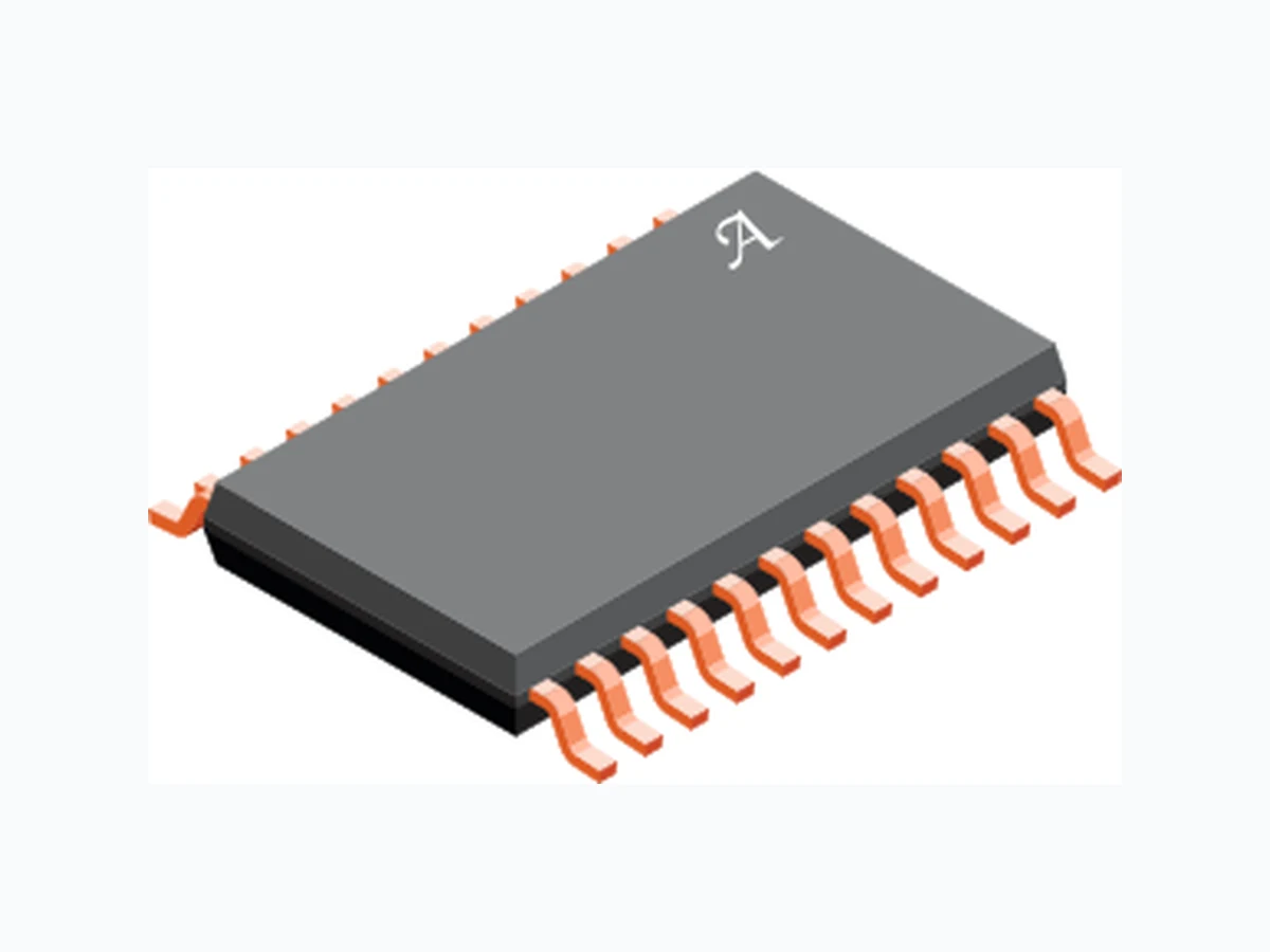
A5929 ALLEGRO
Document overview
- Manufacturer or author: Provided By www.digicamel.com(FREE DATASHEET DOWNLOAD SITE)
- PDF pages: 17
Technical content
The A5929 is a full-bridge controller for use with n-channel external power MOSFETs and is specifically designed for automotive applications. A unique charge pump regulator provides full (>10 V) gate drive at battery voltages down to 7 V and allows the A5929 to operate with reduced gate drive at battery voltages down to 5.5 V . A bootstrap capacitor is used to provide the above battery supply voltage required for n-channel MOSFETs. One logic level input is provided for each of the four power MOSFETs in the full-bridge, allowing motors to be driven with any PWM scheme defined by an external controller. The power MOSFETs are protected from cross-conduction by integrated crossover control. Motor phase short-to-supply and short-to-ground detection is provided by independent drain-source voltage monitors on each MOSFET. Short faults, supply undervoltage, and chip over-temperature conditions are indicated by a single open drain fault output. The A5929 is supplied in a 24-pin TSSOP power pack- age with an exposed thermal pad (package type LP). This package is available in lead (Pb) free versions, with 100% matte-tin lead frame plating (suffix –T). A5929-DS
- High current Full-Bridge gate drive for n-channel MOSFETs
- Cross-conduction protection
- 5.5 V to 50 V Supply V oltage Range
- Motor phase short to supply and short to ground detection
- Undervoltage, overtemperature monitors
- Low Current Sleep Mode Automotive Full-Bridge MOSFET Driver Typical Application Diagram Not to scale A5929 MCU A5929 VDD VBAT PACKAGE: 24-Pin eTSSOP with exposed thermal pad (suffix LP) FEATURES AND BENEFITS DESCRIPTION
Automotive Full-Bridge MOSFET DriverA5929 Allegro MicroSystems, LLC
115 Northeast Cutoff
Worcester, Massachusetts 01615-0036 U.S.A. Absolute Maximum Ratings 1 Characteristic Symbol Notes Rating Unit Load Supply Voltage VBB -0.3 to 50 V Terminal VREG -0.3 to 16 V Terminals CP1, CP2 -0.3 to 16 V Logic Inputs AHI, ALO, BHI, BLO, and ENAB -0.3 to 6.5 V Terminal VBRG -5 to 55 V Terminal LSS -4 to 6.5 V Terminals SA, SB -5 to 55 V Terminals GHA, GHB Sx to Sx+15 V Terminals GLA, GLB -5 to 16 V Terminals CA, CB -0.3 to Sx+15 V Terminal FAULT -0.3 to 6.5 V Terminal VDSTH -0.3 to 6.5 V Ambient Operating Temperature Range 2 TA -40 to 150 ºC Maximum continuous junction temperature TJ(max) 165 ºC Transient Junction Temperature TtJ Over temperature event not exceeding 10s, lifetime duration not exceeding 10hours, determined by design characterisation. 175 ºC Storage Temperature Range Tstg -55 to 150 ºC 1 With respect to GND. 2 Limited by power dissipation. Thermal Characteristics 3 may require derating at maximum conditions Characteristic Symbol Test Conditions Value Unit Package Thermal Resistance RθJA 4-layer PCB based on JEDEC standard 28 ºC/W 2-layer PCB with 3.8 in2 Copper each side 38 ºC/W RθJP 2 ºC/W 3Additional thermal information available on the Allegro website. Selection Guide Part Number Packing Package A5929KLPTR-T 4000 pieces per reel 9.7mm x 4.4mm, 1.2mm nominal height 24 lead TSSOP with exposed thermal pad SPECIFICATIONS
Automotive Full-Bridge MOSFET DriverA5929 Allegro MicroSystems, LLC Worcester, Massachusetts 01615-0036 U.S.A. Package LP, 24-Pin eTSSOP Pin-out Diagram Number Name Function
1 LSS Common Low-side Source
2 NC No connect
3 GLB Phase B Low-side Gate Drive
4 GHB Phase B High-side Gate Drive
5 SB Phase B Motor Connection
6 CB Phase B Bootstrap Capacitor
7 GLA Phase A Low-side Gate Drive
8 GHA Phase A High-side Gate Drive
9 SA Phase A Motor Connection
10 CA Phase A Bootstrap Capacitor
11 NC No connect
12 VREG Gate Drive Supply Output
14 CP1
15 VBB
16 VBRG
17 GND
18 ENAB
19 VDSTH
20 FAULT
21 AHI
22 ALO
23 BHI
24 BLO
13 CP2 Pump Capacitor
14 CP1 Pump Capacitor
15 VBB Main Power Supply
16 VBRG High-side Drain voltage sense
17 GND Ground
18 ENAB Enable Input
19 VDSTH VDS Monitor Threshold Voltage
20 FAULT Diagnostic output
21 AHI Phase A HS control
22 ALO Phase A LS control
23 BHI Phase B HS control
24 BLO Phase B LS control
– PAD Exposed thermal pad-Connect to GND
Automotive Full-Bridge MOSFET DriverA5929 Allegro MicroSystems, LLC Worcester, Massachusetts 01615-0036 U.S.A. ENAB AHI ALO BHI BLO FAULT VDSTH PAD GND VBB CP1 CP2 VREG VBRG CA GHA SA GLA LSS CB GHB SB GLB VBATCharge Pump Regulator Logic Supply Regulator Control Logic Diagnostics & Protection Phase A As Above for Phase B CP Battery + CBOOTA RGHA RGLA CBOOTB RGHB RGLB HS Drive LS Drive VDS Monitor VDS Monitor VREG Functional Block Diagram
Automotive Full-Bridge MOSFET DriverA5929 Allegro MicroSystems, LLC Worcester, Massachusetts 01615-0036 U.S.A. Characteristic Symbol Test Conditions Min. Typ. Max. Unit Supply & Reference VBB Functional Operating Range 2 Correct Function Parameters not Guaranteed 5.5 – 50 V VBB Quiescent Current IBBQ Operational Mode, Outputs Low VBB = 12 V – 6 14 mA IBBS Sleep Mode, VBB = 12 V, ENAB < 0.6 V – – 10 µA VREG Output Voltage VREG VBB > 9 V, IREG = 0 mA to 15 mA 12.5 13 13.75 V 7.5 V < VBB ≤ 9 V, IREG = 0 mA to 10 mA 12.0 13 13.75 V 6 V < VBB ≤ 7.5 V, IREG = 0 mA to 9 mA 2×VBB-3.0 – – V 5.5 V < VBB ≤ 6 V, IREG < 8 mA 8.5 9.5 – V Bootstrap Diode Forward Voltage VfBOOT ID = 10 mA 0.4 0.7 1.0 V ID = 100 mA 1.5 2.2 3.1 V Bootstrap Diode Resistance rD rD(100 mA) = (VfBOOT(150 mA) – VfBOOT(50 mA))/ 100 mA 6 13 28 Ω Bootstrap Diode Current Limit IDBOOT 250 500 750 mA Disable Time tSLT From ENAB < VIL to Gxx low 200 ns Sleep Mode Activation Timeout tSLT From ENAB < VIL 7.5 10 12.5 ms Wake Up from Sleep Delay tWK ENAB > VIH. CREG < 1 µF – – 1 ms Gate Output Drive Turn-on Time tr CLOAD = 1 nF, 20% to 80% – 35 – ns Turn-off Time tf CLOAD = 1 nF, 80% to 20% – 20 – ns Pull-up On Resistance RDS(on)UP TJ = 25°C, IGHx = -150 mA 5 8 13 Ω TJ = 150°C, IGHx = -150 mA 10 15 24 Pull-down On Resistance RDS(on)DN TJ = 25°C, IGLx = 150 mA 1.5 2.4 4.6 Ω TJ = 150°C, IGLx = 150 mA 2.5 4 6.5 GHx Output Voltage High VGHH Bootstrap Capacitor fully charged VCx -0.2 – – V GHx Output Voltage Low VGHL – – VSX+0.3 V GLx Output Voltage High VGLH VREG-0.2 – – V GLx Output Voltage Low VGLL – – VLSS+0.3 V GHx Passive Pull-down RGHPD VGHx - VSx < 0.3 V – 400 – kΩ GLx Passive Pull-down RGLPD VGLx - VLSS < 0.3 V – 400 – kΩ Turn-off Propagation Delay 3 tP(off) Input change to unloaded Gate output change 60 90 180 ns Turn-on Propagation Delay 3 tP(on) Input change to unloaded Gate output change 60 90 180 ns Prop Delay Matching – Phase to Phase DtPP Same phase change – 10 – ns Prop Delay Matching - On to Off DtOO Single phase – 30 – ns Continued on the next page… ELECTRICAL CHARACTERISTICS: valid at TJ = -40 to +150°C, VBB = 7 to 50 V; unless otherwise specified
Automotive Full-Bridge MOSFET DriverA5929 Allegro MicroSystems, LLC Worcester, Massachusetts 01615-0036 U.S.A. Characteristic Symbol Test Conditions Min. Typ. Max. Unit Logic Inputs & Outputs Input Low Voltage (xHI, xLO) VIL – – 0.8 V Input High Voltage (xHI, xLO) VIH 2.0 – – V Input Low Voltage (ENAB) VIL – – 0.8 V Input Low Voltage (ENAB) VIL Minimum power sleep mode – – 0.6 V Input High Voltage (ENAB) VIH 2.0 – – V Input Hysteresis (xHI, xLO) (ENAB) VIhys 100 300 – mV Input Pull-down Resistor (xHI, xLO) RPD – 50 – kΩ Input Pulse Filter Time (xHI,xLO) tPIN – 35 – ns VDS Disable Voltage VDSD – – 100 mV Fault Disable Voltage VFLTD – – 0.5 V Output Low Voltage (FAULT) VOL IOL = 1 mA. No Fault indicated – 0.2 0.4 V Output Leakage (FAULT)1 IO 0 V < VO < 5.5 V, Fault indicated -1 – 1 µA Protection VREG Undervoltage Lockout VREGON VREG rising 7.5 8 8.5 V VREGOFF VREG falling 6.75 7.25 7.75 V Bootstrap Undervoltage VBOOTUV VBOOT falling, VCx – VSx 62 – 75 %VREG Bootstrap Undervoltage Hysteresis VBOOTHys – 9 – %VREG VDS Threshold Internal VDSTHI VDSTH > 2.7 V 1.1 1.2 1.3 V VDS Threshold Range VDSTH 0.2 – 2 V VDS Threshold Input Leakage VDSTHL 0 V < VDSTH < 5.5 V -3 – 3 µA VBRG Input Voltage VBRG VBB-1 VBB VBB+1 V VBRG Input Current IVBRG VDSTH = 2 V, VBB = 12 V; 0 V < VBRG < VBB – – 250 µA Short-to-Ground Threshold Offset VSTGO VDSTH ≥ 1 V – ±100 – mV VDSTH < 1 V -150 ±50 +150 Short-to-Battery Threshold Offset VSTBO VDSTH ≥1 V – ±100 – mV VDSTH <1V -150 ±50 +150 VDS Fault Blank Time tBL 1.5 2.3 4.5 µs Over-temperature Warning TJF Temperature increasing 170 – 180 ºC Over-temperature Hysteresis TJHyst Recovery = TJF - TJHyst – 15 – ºC 1 For input and output current specifications, negative current is defined as coming out of (sourced by) the specified device terminal. 2 Function is correct but parameters are not guaranteed below the general limits (7V). 3 See Figure 1 for gate drive output timing. ELECTRICAL CHARACTERISTICS (continued): valid at TJ = -40 to +150°C, VBB = 7 to 50 V; unless otherwise specified xH xL GHx GLx tP(off) tP(off)tP(on) tP(on) Figure 1: Gate Drive Timing
Automotive Full-Bridge MOSFET DriverA5929 Allegro MicroSystems, LLC Worcester, Massachusetts 01615-0036 U.S.A. FUNCTIONAL DESCRIPTION The A5929 provides four high current gate drives capable of driv- ing a wide range of n-channel power MOSFETs. The gate drives are configured as two high-side and two low-side drives. The four gate drives are controlled by individual TTL-threshold logic inputs which may be driven from 3.3 V or 5 V logic outputs. The A5929 provides all necessary circuitry to ensure that the gate-source turn-on voltages of both high-side and low-side external MOSFETs are driven above 10 V at supply voltages down to 7 V . For extreme low battery voltage conditions, cor- rect functional operation is maintained down to 5.5 V but with a reduced gate drive. The control inputs to the A5929 provide a simple solution for many motor drive applications controlled by an external micro- controller or DSP. Phase commutation and PWM control must be managed by the external system controller. Specific device functions are described more fully in the follow- ing sections. Input & Output Terminal Functions VBB Power supply for all device functions including internal logic and Charge Pump. System power should be connected to VBB through a reverse voltage protection circuit. The VBB pin should be decoupled to ground with ceramic capacitors mounted physically close to the device pins. CP1, CP2 Pump capacitor connection for charge pump. Connect a minimum 220nF, typically 470nF, between CP1 and CP2. VREG Regulated voltage, nominally 13 V , used to supply the low side gate drivers and to charge the bootstrap capacitors. A sufficiently large storage capacitor must be connected to this terminal to provide the transient charging current. GND Analogue reference, Digital and power ground. Connect to sup- ply ground – see layout recommendations. CA, CB High-side connections for the bootstrap capacitors and positive supply for high-side gate drivers. GHA, GHB High-side, gate-drive outputs for external n channel MOSFETs. SA, SB Load phase connections. Used to sense the voltages switched across the load. Also connected to the negative side of the boot- strap capacitors and constitute the negative supply connections for the floating high-side drivers. GLA, GLB Low-side, gate-drive outputs for external n-channel MOSFETs. LSS Low-side return path for discharge of the capacitance on the MOSFET gates, connected to the common sources of the low- side external MOSFETs through a low impedance track. VBRG Sense input to the top of the external MOSFET bridge. Allows accurate measurement of the voltage at the drains of the high side MOSFETs. AHI, BHI Input to control the high-side gate drives. A logic high commands the relevant high-side gate drive to be activated. ALO, BLO Input to control the low-side gate drives. A logic high commands the relevant low-side gate drive to be activated. ENAB Enable input to control all outputs and sleep mode. A logic high enables the outputs to be active. A logic low immediately disables all gate drive outputs and causes the A5929 to enter sleep mode after the Sleep Mode Activation Timeout. FAULT Open drain active-high fault output. If a fault is present the open-
Automotive Full-Bridge MOSFET DriverA5929 Allegro MicroSystems, LLC Worcester, Massachusetts 01615-0036 U.S.A. drain pull-down is off and the FAULT input may be pulled high by an external pull-up resistor connected to any voltage up to a maximum of 5.5 V . VDSTH Drain source fault threshold programming pin. The VDS fault threshold may be set by applying an externally generated analogue voltage. VDS fault reporting is disabled if VDSTH is driven to less than VDSD (e.g. shorted to ground). The VDS fault threshold is set to an internally hardwired value, VDSTHI, if VDSTH is driven to a voltage above its specified analogue input range (e.g. pulled up to the system logic supply voltage). Power Supplies A single supply voltage (VBB) applied to the VBB terminal powers all device functions including on-chip logic, analogue circuitry, and output drivers. It should be connected to the positive supply through a reverse voltage protection circuit and decoupled by a ceramic capacitor mounted close to the VBB and GND terminals. The A5929 will operate within specified performance limits with VBB between 7V to 50V and will function correctly with VBB as low as 5.5V . Sleep Mode A low power ‘sleep’ mode is activated when a logic low is applied to the ENAB input for a period equal to the Sleep Mode Activation Timeout (tSLT). As soon as ENAB is low all gate drive outputs will be switched off. Once in sleep mode all outputs are switched to a high impedance state. Operating mode is active within a period equal to the Wake Up from Sleep Delay (tWK) from a logic high being detected on the ENAB input. It is recommended that all xLO inputs are simulta- neously driven to logic high (GLx turned on) when waking from sleep in order to recharge the bootstrap capacitors and enable subsequent high side turn on. CP1,CP2, VREG The gate drivers are powered by an internal regulator which limits the supply to the drivers and therefore the maximum gate voltage. For VBB supply greater than approximately 16V the regulator operates in a linear regulator mode. Below 16V the regulated supply is maintained by a charge pump boost converter which requires a pump capacitor, typically 470 nF, connected between the CP1 and CP2 terminals. The regulated voltage, nominally 13 V , is available on the VREG terminal. A sufficiently large storage capacitor (See applications section) must be connected to this terminal to provide the tran- sient charging current to the low side drivers and the bootstrap capacitors. Gate Drives The A5929 is designed to drive external, low on-resistance, power n channel MOSFETs. It will supply the large transient currents necessary to quickly charge and discharge the external MOSFET gate capacitances in order to reduce dissipation in the external MOSFET during switching. Charge current for the low- side drives is provided directly by the capacitor on the VREG terminal. Charge current for the high-side drives is delivered via the bootstrap capacitors connected, one per phase, across the Cx, Sx terminal pairs. Charge and discharge rate can be controlled by incorporating an external resistor in series with each MOSFET gate drive (GHx, GLx). High-side Gate Drive. GHA/GHB High-side, gate-drive outputs for external n channel MOSFETs. An external resistor between the GHx gate drive output and the MOSFET gate terminal (mounted as close to the latter as pos- sible) may be used to control the slew rate at the gate, thereby controlling the di/dt and dv/dt of the voltage at the Sx terminals. GHx “high” turns on the upper half of the driver, sourcing cur- rent to the gate of the high-side MOSFET in the external motor- driving bridge, turning it on. GHx “low” turns on the lower half of the driver, sinking current from the external MOSFET’s gate circuit to the respective Sx terminal, turning it off. Bootstrap Charge Management Bootstrap capacitors are charged to approximately VREG when the associated Sx terminal is driven low. When the Sx terminal subsequently swings high, the capacitor provides the necessary voltage for high-side n-channel power MOSFET turn-on. At sys- tem start up it is necessary to turn on each low side drive (GLx) prior to attempting to turn on the complementary high side (GHx) in order to charge the bootstrap capacitors.
Automotive Full-Bridge MOSFET DriverA5929 Allegro MicroSystems, LLC Worcester, Massachusetts 01615-0036 U.S.A. Low-side Gate Drive. GLA/GLB The low-side, gate-drive outputs on GLA and GLB are referenced to the LSS terminal. These outputs are designed to drive external n-channel power MOSFETs. An external resistor between the GLx gate drive output and the MOSFET gate terminal (mounted as close to the latter as possible) may be used to control the slew rate at the gate, thereby providing some control of the di/dt and dv/dt of the voltage at the Sx terminals. GLx “high” turns on the upper half of the driver, sourcing current to the gate of the low- side MOSFET in the external motor-driving bridge, turning it on. GLx “low” turns on the lower half of the driver, sinking current from the external MOSFET’s gate circuit to the to the LSS termi- nal, turning it off. Drain Source Voltage Monitor The VDS fault threshold is set by applying a control voltage on the VDSTH pin as detailed in Figure 2. If a voltage between 0.2 V and 2.0 V is applied the threshold will follow this level subject to the Short to Ground Threshold (VSTGO) and Short to Battery Threshold (VSTBO) Offsets detailed in the Electrical Characteristics table. If a voltage between 2.0 V and 2.3 V is applied the threshold will approximate the applied level but accuracy is not specified. If the VDSTH pin is driven below the VDS Disable V oltage (VDSD) of 0.1 V (e.g. shorted to ground) VDS fault reporting is disabled. If the VDSTH pin is taken above 2.7 V (e.g. pulled up to the sys- tem logic supply voltage) the threshold is set to the VDS Thresh- old Internal (VDSTH) voltage detailed in the Electrical Character- istics table (typically 1.2 V). The VDSTH pin presents a high impedance at all voltages across its permissible input range (per the VDS Threshold Input Leak- age limits detailed in the Electrical Characteristics table, VDSTHL) allowing a wide range of programming circuits to be used includ- ing simple resistive dividers. The VDSTH input has an internal passive first-order filter with a time constant of approximately 10 µs. Additional filter capaci- tance may be added externally if required. Logic Control Inputs A set of discrete digital inputs (xHI, xLO) provides direct control of the four gate drive outputs (GHx, GLx). TTL input threshold levels ensure these can be driven from 3.3 V or 5 V logic sys- tems. 5.5 V 2.7 V 2.3 V 2.0 V 0.2 V 0.1 V 0 V VDSD VDSTH(min) VDSTH(max) Internal External External Disable Intermediate Intermediate Threshold set to internal value (V )DSTHI with accuracy specified in Electrical Characteristics table. Threshold set to voltage approx. equal to that applied on VDSTH pin. Accuracy not specified. Threshold set to voltage applied on VDSTH pin with accuracy specified in Electrical Characteristics table. VDSTH pin typically tied to system logic supply voltage. Behaviour indeterminate due to threshold detection uncertainty. Figure 2: VDSTH Pin Voltage versus VDS Monitor Function
Automotive Full-Bridge MOSFET DriverA5929 Allegro MicroSystems, LLC Worcester, Massachusetts 01615-0036 U.S.A. Setting a logic input high causes the corresponding gate drive output to swing high thereby commanding the associated external MOSFET to turn on. Conversely, setting a logic input low swings the corresponding gate drive low commanding the MOSFET off. Internal lock-out logic ensures that the high-side output drive and low-side output drive cannot be active simultaneously as detailed in Table 1. Table 1: Phase Control Truth Table Input Output Comments ENAB xHI xLO GHx GLx Sx 1 0 0 L L Z Phase disabled 1 0 1 L H LO Low-side active 1 1 0 H L HI High-side active 1 1 1 L L Z Phase disabled
0 X X L L Z All disabled
0 X X Z Z Z Sleep Mode
HI ≡ high-side MOSFET active, LO ≡ low-side MOSFET active X ≡ don’t care, Z ≡ high impedance, both MOSFETs off An additional enable input, ENAB, may be used to turn all out- puts off. ENAB must be high for the outputs to be active. When ENAB is held low for longer than the Sleep Mode Activation Time (tSLT) then the A5929 will enter sleep mode. Diagnostics Several diagnostic features are integrated into the A5929 to provide indication of fault conditions. In addition to system wide faults such as under voltage and over temperature, the A5929 integrates individual monitors for each bootstrap capacitor volt- age and each exeternal MOSFET drain-source voltage. The presence of a fault condition is indicated on the FAULT pin. This is an open drain output that should be pulled to any voltage up to 5.5 V by an external resistor, typically 10 kΩ to 47 kΩ. The definition of the individual fault states and the effect on the gate drive outputs (GHx, GLx) are shown in Table 2 and described below. Table 2: Fault Definitions FAULT Fault Description Outputs Disabled Fault Latched Low No Fault No - High Overtemperature No No High VREG undervoltage Yes1 No High VDS overvoltage No No High Bootstrap undervoltage Yes2 Yes 1 All gate drives low (external MOSFETs off).
2 High side drive of phase generating FAULT condition set low (external MOSFET
off). Other outputs unaffected. Fault States It is recommended that any external control circuitry remaining active in the event of a fault state being flagged is configured to take appropriate action to prevent damage to the A5929 and associated motor drive components. Overtemperature. If junction temperature exceeds the over- temperature warning threshold (TJF) the A5929 enters the over- temperature warning state and FAULT goes high. The over-tem- perature warning state is cleared and the FAULT output returned to logic low when the junction temperature drops below recovery level TJF - TJFhys. Whilst an over-temperature warning state is asserted no on-chip circuitry or functions are disabled. VREG UNDERVOLTAGE The charge pump generates VREG to provide low-side gate driver and bootstrap charge current. It is necessary to ensure that this voltage is high enough prior to enabling any of the gate drive outputs. If the voltage at the VREG pin drops below the falling VREG Undervoltage Lockout Threshold (VREGUV off ) the A5929 enters the VREG undervoltage fault state, FAULT is set high, and all gate drive outputs (GHx, GLx) are disabled. The VREG undervoltage fault state is cleared and FAULT goes low when VREG rises above the VREG undervoltage lockout threshold (ris- ing), VREGUV on. The VREG undervoltage monitor circuit is active during power- up and the A5929 remains in the VREG undervoltage fault state until VREG is greater than the rising VREG undervoltage lockout threshold, VREGUV on.
Automotive Full-Bridge MOSFET DriverA5929 Allegro MicroSystems, LLC Worcester, Massachusetts 01615-0036 U.S.A. VDS OVERVOLTAGE When a gate drive output is commanded to turn on (GHx or GLx high) the the drain-source voltage of the corresponding external MOSFET is monitored between VBRG and Sx or Sx and LSS as appropriate. If the measured voltage exceeds the threshold value programmed on the VDSTH pin the FAULT output is set high but none of the gate drive outputs is disabled. Propagation of any fault states to the FAULT output is disabled for the VDS Fault Blank Time (tBL) at every external MOSFET turn-on event to avoid reporting spurious faults in response to switching tran- sients. If a fault is reported on the FAULT pin it will be cleared as soon as the measured drain-source voltage drops below the programmed VDSTH level. BOOTSTRAP CAPACITOR UNDERVOLTAGE Each bootstrap capacitor is monitored to ensure sufficient high- side gate drive voltage is available to initiate and maintain exter- nal MOSFET turn-on . High-side gate drive outputs only turn on if the relevant bootstrap capacitor voltage is higher than the bootstrap turn-on voltage threshold, VBOOTUV + VBOOTHys. If the bootstrap voltage is below this threshold when turn on is command on xHI the cor- responding gate drive, GHx, is not switched on and FAULT is set high. The output remains off and FAULT remains high until either the affected gate drive is commanded to turn off or the FAULT pin is pulled low by external means (see FAULT pin dis- able description below). After a high side gate drive has been successfully turned on the appropriate bootstrap capacitor voltage must remain above the Bootstrap Undervoltage threshold (VBOOTUV). If the bootstrap capacitor voltage drops below VBOOTUV the high side driver in question is switched off and FAULT goes high. The driver will remain off and FAULT will remain high until either the affected high-side gate drive turn on commanded is removed from xHI or the FAULT pin is pulled low by external means (see FAULT pin disable description below). If a bootstrap capacitor fault condition is detected only the driver in question is disabled. All other gate drives continue to respond to control inputs on xHI, xLO. If the FAULT pin is held low (below the Fault Disable V oltage (VFLTD) by external means the bootstrap undervoltage moni- tor feature is disabled. In this condition, if bootstrap capacitor voltage fails to reach VBOOTUV + VBOOTHys for turn on or drops below VBOOTUV after turn on the driver in question is not forced into the off state. As the FAULT pin is held low, a fault state is not flagged. Whilst the FAULT pin is held low to disable the bootstrap undervoltage monitor any other fault conditions that might arise are undetectable outside the A5929. However, inter- nal fault actions are unaffected and gate drive outputs are still disabled in response to other faults in accordance with Table 2.
Automotive Full-Bridge MOSFET DriverA5929 Allegro MicroSystems, LLC Worcester, Massachusetts 01615-0036 U.S.A. APPLICATIONS INFORMATION Power Bridge Management Using PWM Control The A5929 provides individual high-side and low-side controls for each phase through the four digital control inputs. The only restriction imposed by the A5929 is to prevent the high-side and low-side gate drive from a single phase being on at the same time to avoid cross-conduction. This allows all H bridge control schemes to be implemented. This includes fast and slow decay, synchronous rectification and diode rectification, and edge aligned and centre aligned PWM. Figure 3(A) shows an example of the path of the bridge and load current. In this example the high-side MOSFETs are switched off during the current decay time (PWM-off time) and load current recirculates through the low-side MOSFETs. This is commonly referred to as high side chopping or high side PWM. During the PWM off-time the complementary MOSFETs are turned on to short the body diode and provide synchronous rectification. Figure 3(A) only shows current in one direction but the same principal applies to current in the opposite direction. The same principal also applies when the low-side MOSFETs are turned off during the PWM off-time and the load current recirculates through the high side MOSFETs as in figure 3(B). In this control scheme the microcontroller has full control over the current decay method, load current recirculation paths, braking and coasting. The A5929 provides exceptional propagation delay matching from logic input to gate drive output for high performance motor control applications. These advanced applications usually require high-resolution PWM control on each phase. This must be provided by an external controller, which must also provide the necessary dead time to avoid shoot through in the power bridge. Bootstrap Capacitor Selection CBOOT must be correctly selected to ensure proper operation of the device. Too large and time will be wasted charging the capaci- tor resulting in a limit on the maximum duty cycle and PWM frequency. Too small and there can be a large voltage drop at the time the charge is transferred from CBOOT to the MOSFET gate. To keep the voltage drop, due to charge sharing, small, the charge in the bootstrap capacitor (QBOOT) should be much larger than QGATE. The charge required by the gate: QBOOT >> QGATE A factor of 20 is a reasonable value. Q= C× V= Q× 20BOOT BOOT BOOT GATE C=BOOT QGATE × 20 VBOOT where VBOOT is the voltage across the bootstrap capacitor. Drive Recirculate Phase AB xH xL GHx GLx H L L H Phase AB xH xL GHx GLx L H L H A B (A) High-side PWM with slow decay and synchronous rectification. Drive Recirculate Phase AB xH xL GHx GLx H L L H Phase AB xH xL GHx GLx H L H L A B (B) Low-side PWM with slow decay and synchronous rectification. Figure 3: Power Bridge Control
Automotive Full-Bridge MOSFET DriverA5929 Allegro MicroSystems, LLC Worcester, Massachusetts 01615-0036 U.S.A. The voltage drop, ΔV , across the bootstrap capacitor as the MOS- FET is being turned on can be approximated by: /c68V= QGATE CBOOT so for a factor of 20, ΔV will be 5% of VBOOT. The maximum voltage across the bootstrap capacitor under normal operating conditions is VREG max. However in some circumstances the voltage may transiently reach 18 V , the clamp voltage of the Zener diode between the Cx terminal and the Sx terminal. In most applications with a good ceramic capacitor the working voltage can be limited to 16 V . Bootstrap Charging It is good practice to ensure the high side bootstrap capacitor is completely charged before a high side PWM cycle is requested. The time required to charge the capacitor (tCHARGE) in µs, is approximated by: 500t=CHARGE C×BOOT /c68V Where CBOOT is the value of the bootstrap capacitor in nF and ΔV is the required voltage of the bootstrap capacitor. At power up and when the drivers have been disabled for a long time, the bootstrap capacitor can be completely discharged . In this case ΔV can be considered to be the full high side drive volt- age, 12 V . Else, ΔV is the amount of voltage dropped during the charge transfer, which should be 400 mV or less. The capacitor is charged whenever the Sx terminal is pulled low and current flows from VREG through the internal bootstrap diode circuit to CBOOT. Supply Decoupling Since this is a switching circuit there will be current spikes from on VBB at the switching points. As with all such circuits the power supply connections should be decoupled with a ceramic capacitor, typically 220 nF, between the supply terminal and ground. These capacitors should be connected as close as possible to the VBB and ground terminal (GND). VREG Capacitor Selection The internal reference (VREG) supplies current for the low-side gate-drive circuits and the charging current for the bootstrap capacitors. When a low-side MOSFET is turned on, the gate- drive circuit will provide the high transient current to the gate that is necessary to turn the MOSFET on quickly. This current, which can be several hundred milliamperes, cannot be provided directly by the limited output of the VREG regulator but must be supplied by an external capacitor connected to VREG. The turn on current for the high-side MOSFET is similar in value but is mainly supplied by the bootstrap capacitor. However the bootstrap capacitor must then be recharged from the VREG regulator output. Unfortunately the bootstrap recharge can occur a very short time after the low-side turn on occurs. This means that the value of the capacitor connected between VREG and GND should be high enough to minimize the transient voltage drop on VREG for the combination of a low-side MOSFET turn on and a bootstrap capacitor recharge. A value of 20 x CBOOT is a reason- able value. The maximum working voltage will never exceed VREG so can be set as low as 15 V . This capacitor should be placed as close as possible to the VREG terminal.
Automotive Full-Bridge MOSFET DriverA5929 Allegro MicroSystems, LLC Worcester, Massachusetts 01615-0036 U.S.A. INPUT/OUTPUT STRUCTURES 20V 20V 14V 18 V 18 V
6 V 6 V 6 V 6 V6 V
18 V 14 V
20 V 20 V
7.5 V 18 V 18 V Cx GHx Sx VREG GLx LSS Figure 4a: Gate Drive Outputs Figure 4c: xHI, xLO Inputs Figure 4d: VDSTH Input Figure 4e: FAULT Output Figure 4b: Supplies CP1 CP2 VBRG VBB 18 V VREG 2 kΩ 4 kΩ 25 Ω 50 kΩ 4,5 V(max) xHI xLO VDSTH FAULT
Automotive Full-Bridge MOSFET DriverA5929 Allegro MicroSystems, LLC Worcester, Massachusetts 01615-0036 U.S.A. LAYOUT RECOMMENDATIONS A5929 VBB VBRG GHB GHA SA SB GLA GLB LSS PADGND VDSTH VREG VDD RS Controller Supply Power Ground Optional Components to Limit LSS Transients Optional Reverse Battery protection + Supply Load Supply Common Figure 5: Supply Routing Suggestion Careful consideration must be given to PCB layout when design- ing high frequency, fast-switching, high-current circuits: The A5929 ground, GND, and the high-current return of the external MOSFETs should return separately to the negative side of the motor supply filtering (DC-link) capacitor. This will mini- mize the effect of bridge switching noise on the A5929. The exposed thermal pad should be connected to GND. Minimize stray inductance by using short, wide copper tracks at the drain and source terminals of all power MOSFETs. This includes motor lead connections, the input power bus, and the common source of the low-side power MOSFETs. This will mini- mize voltages induced by fast switching of large load currents. Consider the use of small (100 nF) ceramic decoupling capacitors across the source and drain of the power MOSFETs to limit fast transient voltage spikes caused by track inductance. Keep the gate discharge return connections Sx and LSS as short as possible. Any inductance on these tracks will cause negative transitions on the corresponding A5929 terminals, which may exceed the absolute maximum ratings. If this is likely, consider the use of clamping diodes to limit the negative excursion on these terminals with respect to GND. The sensitive VDSTH input should be connected independently close to the GND terminal. The decoupling capacitors should also be connected as close as possible to the relevant supply terminal. Check the peak voltage excursion of the transients on the LSS terminal with reference to the GND terminal using a close- grounded (tip & barrel) probe. If the voltage at LSS exceeds the absolute maximum in the datasheet, add additional clamping and/ or capacitance between the LSS terminal and the GND terminal as shown. Gate charge drive paths and gate discharge return paths may carry a large transient current pulse. Therefore the traces from GHx, GLx, Sx (x = A or B) and LSS should be as short as possible to reduce the track inductance. Provide an independent connection from LSS to the common point of the power bridge. It is not recommended to connect LSS directly to the GND terminal as this may inject noise into sensi- tive functions such as the various voltage monitors. A low cost diode can be placed in the connection to VBB to pro- vide reverse battery protection. In reverse battery conditions it is possible to use the body diodes of the power MOSFETs to clamp the reverse voltage to approximately 4 V . In this case the addi- tional diode in the VBB connection will prevent damage to the A5929 and the VBRG terminal will survive the reverse voltage.
Automotive Full-Bridge MOSFET DriverA5929 Allegro MicroSystems, LLC Worcester, Massachusetts 01615-0036 U.S.A. Figure 6: Package LP, 24-Pin eTSSOP with Exposed Thermal Pad For Reference Only – Not for Tooling Use (Reference MO-153 ADT) NOT TO SCALE Dimensions in millimeters Dimensions exclusive of mold flash, gate burrs, and dambar protrusions Exact case and lead configuration at supplier discretion within limits shown A
1.20 MAX
0.15 0.00 0.30 0.19 0.20 0.09 0.60 ±0.15 1.00 REF C SEATING PLANE C0.10 24X
0.65 BSC
0.25 BSC
7.80 ±0.10 GAUGE PLANE SEATING PLANE A B B Exposed thermal pad (bottom surface); dimensions may vary with device
4.32 NOM
3 NOM
0.65 6.103.00 4.32 1.65 0.45 C C PCB Layout Reference View Terminal #1 mark area Reference land pattern layout (reference IPC7351 TSOP65P640X120-25M); all pads a minimum of 0.20 mm from all adjacent pads; adjust as necessary to meet application process requirements and PCB layout tolerances; when mounting on a multilayer PCB, thermal vias at the exposed thermal pad land can improve thermal dissipation (reference EIA/JEDEC Standard JESD51-5) CUSTOMER PACKAGE DRAWING
Automotive Full-Bridge MOSFET DriverA5929 Allegro MicroSystems, LLC Worcester, Massachusetts 01615-0036 U.S.A. Copyright ©2015, Allegro MicroSystems, LLC Allegro MicroSystems, LLC reserves the right to make, from time to time, such departures from the detail specifications as may be required to permit improvements in the performance, reliability, or manufacturability of its products. Before placing an order, the user is cautioned to verify that the information being relied upon is current. Allegro’s products are not to be used in any devices or systems, including but not limited to life support devices or systems, in which a failure of Allegro’s product can reasonably be expected to cause bodily harm. The information included herein is believed to be accurate and reliable. However, Allegro MicroSystems, LLC assumes no responsibility for its use; nor for any infringement of patents or other rights of third parties which may result from its use. For the latest version of this document, visit our website: www.allegromicro.com
Revision History
Revision Revision Date Description of Revision – February 11, 2015 Initial Release