
X10594 UNITEDAUTOMATION
Document overview
- Manufacturer or author: Provided By www.digicamel.com(free datasheet download site)
- PDF pages: 4
Technical content
V YOU MUST READ THIS BEFORE INSTALLATION ELECTRICAL SAFETY INSTALLATION REQUIREMENTS USER RESTRICTIONS USAGE ENVIRONMENT HOT SURFACE WARNING WARNING: RISK OF ELECTRIC SHOCK Always consult the Installation & Maintenance Instructions before connecting this product to the power supply. WARNING: Disconnect Power Before Servicing Ensure the electrical supply is safely disconnected before connecting to any supply, load, or control terminals. WARNING: Installation by Qualified Personnel Only This product must only be installed or fitted by a competent, qualified installer familiar with the relevant electrical standards and installation practices. WARNING: Not for Use by Vulnerable Individuals This product is not intended for use by persons (including children) with reduced physical, sensory or mental capabilities, or lack of experience and knowledge, unless they are supervised or instructed by a person responsible for their safety. WARNING: Industrial Use Only This is an industrial-grade product and is not intended for household use. WARNING: Hot Surfaces On certain models, surfaces marked with this symbol become hot during use. Avoid direct contact and follow all thermal safety precautions. More Info: https://united-automation.com/general-product-safety-regulation-gpsr/
18 May 2026 | Issue: 12 Page 1 of 4
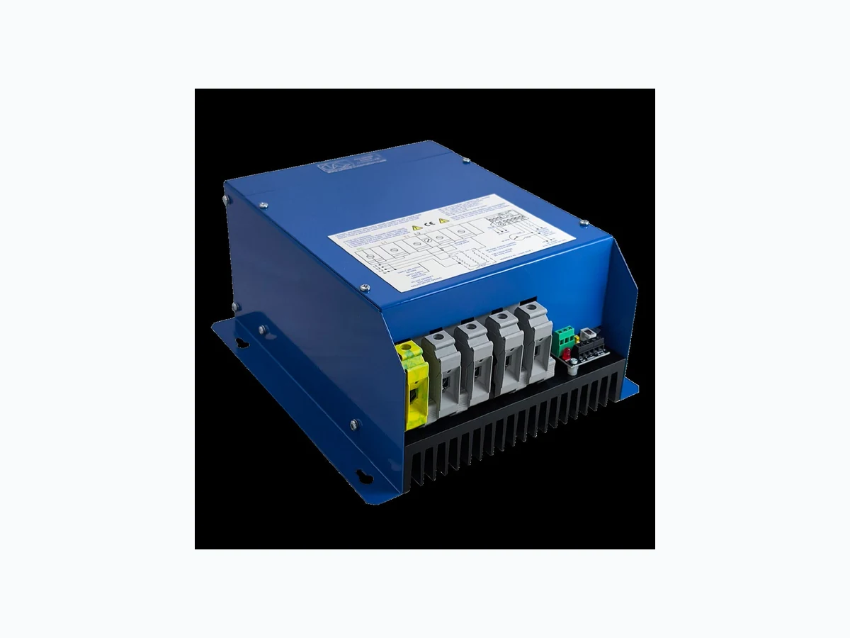
HVAC | HEATER BATTERY CONTROLLER PR3-E Series X10594 86kW (120A), 105kW (146A), 415V Three Phase Burst Fire Power Controller 0044 (0) 1704-516 501 enquiries@united-automation.com www.united-automation.com CONTACT US: KEY FEATURES: The PR3-E Series is a robust range of 3 -phase burst fire power controllers designed for seamless control of resistive loads in HVAC systems and other high- demand applications. Available in 86kW and 105kW models, these thyristor stacks provide precise, reliable power management using advanced two- thirds control techniques. Ideal for air curtains, furnaces, ovens, and more, the PR3- E Series ensures optimal performance with minimal interference, thanks to fast pulse zero-voltage switching technology. The PR3-E Series 3- Phase Burst Fire Power Controllers are engineered for durability and efficiency, offering a powerful solution for managing high- capacity resistive loads in demanding environments. Whether for HVAC or industrial heating applications, this range provides precise control, easy installation, and reliable operation, ensuring your systems run smoothly and safely. Versatile Control: Supports DC signal and 5kΩ potentiometer manual control. Advanced Burst Firing: Minimises flicker and RFI with fast pulse zero-voltage switching. Safety Features: Auto- reset temperature trip, semiconductor fuses, and heatsink. User-Friendly: Easy access to terminals for simple installation. Robust Performance: Ideal for 3-phase resistive loads in HVAC and industrial applications. TECHNICAL SPECIFICATIONS Power/Current Rating 86kW (120A); 105kW (146A) @ a typical supply of 415V RMS Input Voltage 400V RMS ± 10% Frequency 50/60Hz Control Input Options Signal (using SW3): 0 to 10V DC (set as standard)/0 to 5V Manual: using 5kΩ potentiometer For 4-20mA Signal: set S/W I/V to “ON”, fit 270Ω (0.25W) across SIG ± and set SW3 to 0-5V Burst Fire Control Options Slow Burst: 1 second proportional time base Fast Burst: variable and un-proportional time base Alarm Relay Functions The voltage-free alarm circuit is rated for 125V AC @ 2A Alarm Relay Status Options SW1 = “OFF” – Relay is continuously energised (normally closed); trips in fault condition SW1 = “ON” – Relay is de-energised (normally open); closes in fault condition Status Indicator (Tracking control signal) status LED indicator changes intensity Cooling Fan Fan fitted Over Temperature Trip in temperature @ 90°C ± 1°C (Status LED indicator ‘flashes’ with ON/OFF rapid pulsing) Trip out temperature @ 85°C ± 1°C Phase Loss Detection Status LED indicator ‘flashes’ ON/OFF continuously in slow 1.5 second intervals Sensor Loss Detection Status LED indicator ‘flashes’ ON/OFF continuously in equal intervals Cable Terminations Phase Power & Earth 35mm2 Rising Clamp Terminal Block Reference Phase (L2) 10mm2 Rising Clamp Terminal Block Remote supply Auxiliary alarm (relay) 2.5mm2 Rising Clamp Terminal Blocks Control signal 2.5mm2 Rising Clamp Terminal Blocks Fusing 86kW 160EET (160A) High-speed Semiconductor type fuse 105kW 200EET (200A) High-speed Semiconductor type fuse Working Temperature 65°C (maximum operational) Dimensions 272mm (D) x 250mm (W) x 130mm (H) – length is viewed with heatsink fins going top to bottom (see photo) Fixing Centres 4 x 6mm holes on centres 227mm (W) x 200mm (D) Weight (all models) 5.2kg APPLICATIONS: Heating, Ventilating, and Air Conditioning (HVAC): Perfect for air curtain systems, ensuring consistent and efficient heating. Industrial Heating: Ideal for use in furnaces, ovens, dryers, and hot plates where precise temperature control is essential.
X10594 HVAC | HEATER BATTERY CONTROLLER PR3-E SERIES 86kW (120A), 105kW (146A), 415V Three Phase Burst Fire Power Controller BMF House - Wight Moss Way, Southport Business Park Southport PR8 4HQ ENGLAND, UNITED KINGDOM Contact Us: 0044 (0) 1704-516 501 enquiries@united-automation.com www.united-automation.com unitedautomationltd UA_Limited 18 May 2026 | Issue: 12 Page 2 of 4 INSTALLATION Cooling Requirements The PR3 series power controller operates efficiently at temperatures up to 65°C with natural cooling. It features a built-in over-temperature trip at 90°C on the heatsink for added safety. For optimal cooling, mount the unit vertically with the heatsink fins oriented top to bottom, ensuring adequate air space around the unit to maximise natural convection. If the unit is installed in an enclosure or cabinet, proper ventilation or forced air -cooling is necessary to maintain performance and prevent overheating. Load Considerations The PR3 series power controllers are designed for 3-wire, 3-phase floating-star or closed-delta configured resistive loads. These controllers are 2-leg thyristor models, making them unsuitable for 4- wire, 3 -phase systems with a star point to neutral configuration. For more detailed information on configured loads, refer to the ‘Application Circuits’ section of our supporting datasheet (APC ref. X10322). Please note that unusual heating loads, such as those using materials like Molybdenum, Platinum, or Tungsten, may have a high hot-to-cold resistance ratio (up to 10:1), resulting in a significantly higher current draw when cold. Fusing and Over-Temperature Protection To ensure optimal protection, it is recommended to use fast -acting semiconductor fuses, as supplied. For further details, refer to the SRA Datasheet X10255. Additionally, it is advisable to install a load break switch and a contact breaker in the load supply. The power supply to the contactor coil should be interrupted by an over -temperature thermostat located in the heater battery and also upon detection of airflow loss. CONNECTIONS The PR3 series features robust power terminals and simple clamp- type connectors for all auxiliary wiring needs. The unit is factory set for an internal power supply. For alternative ‘voltage-free’ alarm supply configurations, please consult the Functions section or contact our Technical Support team for further assistance. For 105KW model a solid conductor needs to be used (50mm2 cross section) Safety Warning: IMPORTANT: Isolate the power supply before removing the cover. Be aware that metal parts, especially the heatsink, may become extremely hot during operation. DO NOT COVER the enclosure's ventilation slots. Essential Precautions:
- Install a load break switch and a contact breaker in the load supply for safety.
- Ensure that the power supply to the contactor coil is interrupted by an over -temperature thermostat located in the heater battery and upon detecting airflow loss.
X10594 HVAC | HEATER BATTERY CONTROLLER PR3-E SERIES 86kW (120A), 105kW (146A), 415V Three Phase Burst Fire Power Controller BMF House - Wight Moss Way, Southport Business Park Southport PR8 4HQ ENGLAND, UNITED KINGDOM Contact Us: 0044 (0) 1704-516 501 enquiries@united-automation.com www.united-automation.com unitedautomationltd UA_Limited 18 May 2026 | Issue: 12 Page 3 of 4 FUNCTIONS Function Description Alarm relay functions (3-way terminal – V/free alarm “NO|NC|C”) The alarm relay circuit features voltage -free relay contacts rated up to 2A @ 125V AC (RMS). Connections are made via the PCB terminal. For alarm relay status options, refer to the SPECIFICATIONS section. The relay and status LED are powered by the interna l supply from the transformer via two 20mm 1A fuses. The relay and LED can only be energised in the event of an over-temperature condition, sensor fault, or phase loss on the L1 phase. For details on remote supply options, consult the relevant section. Over-Temperature Protection When the heatsink temperature exceeds 90°C, the sensor triggers the alarm relay to change state, and the status LED indicator flashes rapidly. The power supply to the load is disconnected and will not resume until the temperature drops to 85°C. Temperature Sensor Loss If the temperature sensor fails, the Status LED indicator will pulse continuously in equal ON/OFF intervals, signaling the fault. Phase Loss with Auxiliary Supply If any of the three-phase inputs fail, the relay changes state, and the LED flashes ON/OFF in slow 1.5-second intervals. This function is only active with a remote supply. Fault Condition The default setting of DIL switch (SW1) is ON, which means the alarm relay is energi sed under fault conditions. Changing SW1 to the OFF position will keep the alarm relay continuously energised until a fault occurs. Remote Supply The unit is factory-set for internal power supply (SW4 in the “INT” position). If a remote 24V AC or DC supply is required for the alarm relay and LED to function during a phase fault, set SW4 to the “EXT” position. Note that the main supply (L1, L2, and L 3) must be active before the remote supply is switched on. Control Options Guide Burst Fire Control (SW2):
- Fast Burst Control (Flicker Inhibited Mode): Set SW2 DIL switch to the “ON” position.
- Slow Burst Control (Basic Burst Firing Mode): Set SW2 DIL switch to the “OFF” position. Control Input Options (SW3 & SW “I/V”) Control input options are connected via the 5V output and “+” and “-” signal terminals. Ensure correct polarity as shown in the CONNECTIONS section.
- SW3: For input voltage signals of 0-5V or 0-10V DC, connect to the “+” and “-” SIGNAL terminals.
- SW3: For manual control using a 5kΩ, 1W potentiometer, use all three terminals: 5V- O/P, “+”, and “-” SIGNAL terminals.
- SW “I/V”: For a 4-20mA input current signal, set DIL switch SW-I/V to “ON,” fit a 270Ω, 0.25W resistor across the “+” and “-” SIGNAL terminals, and set SW3 to 0-5V. Note that SW-I/V is internal, and the cover must be removed to set it, only after disconnecting the power. The default factory setting is 0-10V (see CONNECTIONS and SPECIFICATIONS sections).
X10594 HVAC | HEATER BATTERY CONTROLLER PR3-E SERIES 86kW (120A), 105kW (146A), 415V Three Phase Burst Fire Power Controller BMF House - Wight Moss Way, Southport Business Park Southport PR8 4HQ ENGLAND, UNITED KINGDOM Contact Us: 0044 (0) 1704-516 501 enquiries@united-automation.com www.united-automation.com unitedautomationltd UA_Limited 18 May 2026 | Issue: 12 Page 4 of 4 RECOMMENDATIONS FUSING It is recommended that high speed semiconductor type fuses (as supplied on SPM models) be used for protection. See SRA Data sheet X10255 for further information. Other external supplies should be fused accordingly. CE Marking This family carries a “CE” marking. These burst fire controllers do not normally require a remote filter. For more information contact our sales desk. A Declaration of Conformity is available on request. DOCUMENTS Other documents available on request, which may be appropriate for your application: Code Identity Description X10213 ITA Interaction: Uses for phase angle and for burst fire control X10255 SRA Safety Requirements: Addressing the Low Voltage Directive (LVD) including, Thermal Data/Cooling, Live Parts Warning, Earthing Requirements and Fusing Recommendations P01.1 COS UAL Conditions of Sale It is recommended that installation and maintenance of this equipment should be done with reference to the current edition of the I.E.T. regulations (BS7671) by suitably qualified/trained personnel. The regulations contain important requirements regarding the safety of electrical equipment. For International standards refer STANDARDS on D of C. OPTIONAL EXTRAS Product Code Product Description T30201 Auxiliary transformer for Failsafe alarm 0/240/415 10-0-10V 2VA A403011 5kΩ, 1W Potentiometer with 0.5m long leads for manual control option Available on request Spare HS fuses: 160EET (160A) or 200EET (200A), SCR-type PRODUCT CODE AND RELATED PRODUCT CODE Product Code Product Description A447412-HV-A PR3-E-86kW, 120A, 415V, 2/3rds control - Three Phase A447432-HV-A PR3-E-105kW, 146A, 415V, 2/3rds control - Three Phase © These products are protected by unregistered design with United Automation Limited, Southport, UK