
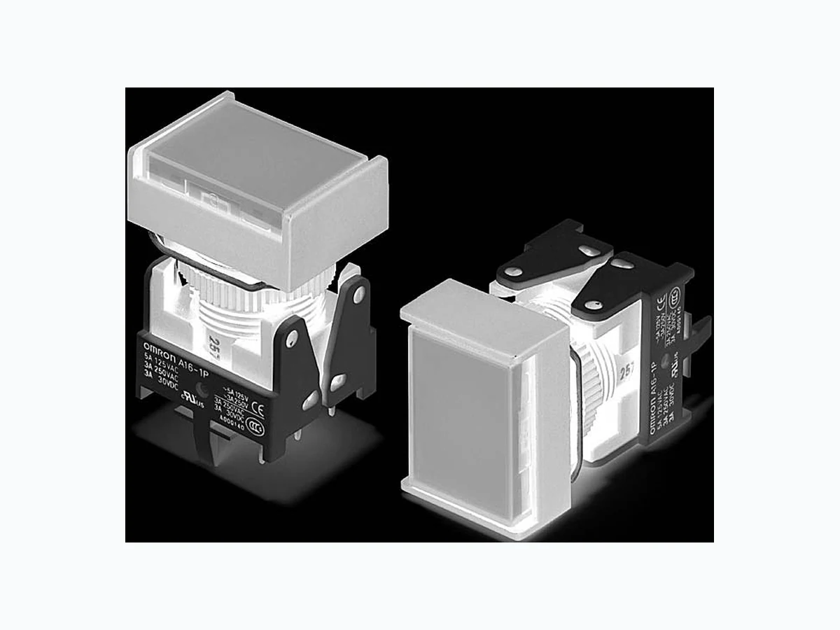
A16L-P OMRON
Document overview
- Manufacturer or author: Provided By digicamel.com
- PDF pages: 4
Technical content
A @ - P A16˘-P Pushbutton Switch (Detachable) (Lighted/Non-Lighted) (Cylindrical 16-dia.) PCB Terminal Models
- Lever made of high heat resistant resin allowing automatic soldering.
- Easy Panel and PCB mounting.
- Lever for easily mounting and removing the Switch.
- The hold status can easily be checked from the rear of the PCB.
- Short profile width of the separable type reduced to 28.3 mm. Panel width can also be reduced. List of Models Pushbutton, Lamp (lighted models only), Case, and Switch. Models with PCB Terminals IP40 Note: Contact your OMRON representative about Selector Switches and Key Selector Switches. *1. Enter the desired shape for the Pushbutton in Δ: J (rectangular), A (square), or T (round). Enter the desired color symbol for the Pushbutton in the @. *2. Black (“B”) Pushbuttons are only available for non-lighted models. Models with PCB Terminals IP66 Note: Contact your OMRON representative about Selector Switches and Key Selector Switches. *1. Enter the desired shape for the Pushbutton in Δ: J (rectangular), A (square), or T (round). Enter the desired color symbol for the Pushbutton in the @. *2. Black (“B”) Pushbuttons are only available for non-lighted models. RoHS Compliant Refer to Safety Precautions for All Pushbutton Switches/ Indicators and Safety Precautions on page 3. Output Lighting Item Momentary operation (Self-resetting) *1 Pushbutton color symbol Minimum packing unitOperating voltage SPDT LED
5 VDC A16L-Δ@M-5D-1P
R: red Y: yellow PY: pure yellow G: green A: blue W: pure white B: black *2 5 pcs
12 VAC/VDC A16L-Δ@M-12D-1P
24 VAC/VDC A16L-Δ@M-24D-1P
Non-lighted A16-Δ@M-1P DPDT LED
5 VDC A16L-Δ@M-5D-2P
12 VAC/VDC A16L-Δ@M-12D-2P
24 VAC/VDC A16L-Δ@M-24D-2P
Non-lighted A16-Δ@M-2P Output Lighting Item Momentary operation (Self-resetting) *1 Pushbutton color symbol Minimum packing unitOperating voltage SPDT LED
5 VDC A165L-Δ@M-5D-1P
R: red Y: yellow PY: pure yellow G: green A: blue W: pure white B: black *2 5 pcs
12 VAC/VDC A165L-Δ@M-12D-1P
24 VAC/VDC A165L-Δ@M-24D-1P
Non-lighted A165-Δ@M-1P DPDT LED
5 VDC A165L-Δ@M-5D-2P
12 VAC/VDC A165L-Δ@M-12D-2P
24 VAC/VDC A165L-Δ@M-24D-2P
Non-lighted A165-Δ@M-2P
A16˘-P Pushbutton Switch (Detachable) (Lighted/Non-Lighted) (Cylindrical 16-dia.) A @ - P Specifications Dimensions (Unit: mm) The Dimension shows 1-switch output. The lamp terminal is also provided with non-lighted models. A rectangular model is listed as an example. Unless specified, there is a tolerance of ±0.4mm for dimensions. ■Characteristics *1. Set and reset constitute one operation. *2. With LED and incandescent lamp not mounted. ■Operating Characteristics * Alternate operation models only. Item Type Pushbutton Switch Allowable operating frequency Mechanical Momentary operation: 120 operations/minute max. Alternate operation: 60 operations/minute max. *1 Electrical 20 operations/minute max. *1 Insulation resistance 100 M Ω min. (at 500 VDC with insulation tester) Contact resistance (initial value) 100 m Ω max. Dielectric strength Between terminals of same polarity 1,000 VAC, 50/60 Hz for 1 minute Between terminals of different polarity 2,000 VAC, 50/60 Hz for 1 minute Between each terminal and ground 2,000 VAC, 50/60 Hz for 1 minute Between lamp terminals 1,000 VAC, 50/60 Hz for 1 minute *2 Vibration resistance Malfunction 10 to 55 Hz, 1.5-mm double amplitude (malfunction within 1 ms) Shock resistance Destruction 500 m/s 2 Malfunction 150 m/s 2 max. (malfunction within 1 ms) Durability Mechanical Momentary operation: 2,000,000 operations min. Alternate operation: 200,000 operations min. *1 Electrical 100,000 operations min. *1 Electric shock protection class Class II PTI (tracking characteristic) 175 Degree of contamination 3 (IEC60947-5-1) Weight Approx. 12 g (in the case of a lighted DPDT switch with solder terminals) Ambient operating temperature –10°C to +55°C (with no icing or condensation) Ambient operating humidity 35% to 85%RH Ambient storage temperature –25°C to +65°C (with no icing or condensation) Characteristics Type IP40 Oil-resistant IP66 Operating force OF max. 4.41 N 4.91 N Release force RF min. 0.29 N Total travel TT Approx. 3mm Pretravel PT max. 2.5 mm Locktravel alternate LTA min.* 0.5 mm ■Approved Standard Ratings
- UL, cUL (File No. E41515) Note: Certification has been obtained for the Switch.
- TÜV (EN60947-5-1) (Low Voltage Directive)
3 A at 250 VAC
3 A at 30 VDC
- CCC (GB14048.5)
5 A at 125 VAC
■Ratings
- Contacts Note: Minimum allowable load:
5 VDC 1 mA (Resistive)
The ratings given above are for testing under the following conditions: (1) Ambient temperature: 20 ± 2°C (2) Ambient humidity: 65 ± 5%RH (3) Operating frequency: 20 times/minute
- Contact Form
5 A at 125 VAC, 3 A at 250 VAC (general use)
3 A at 30 VDC (resistive)
Rated voltage Resistive load
125 VAC 5
250 VAC 3
30 VDC 3
18 15.1 0.5 0.5 4.85 18.6 18.4 20.4 6.3 2.5 12.4 23.1 28.3 26.4 21.1 10.8 9.5 Lock ring Mounting nut Packing (t0.5) (for oil-resistant IP66 only) Rectangular A16@-J@-@P PCB terminals
A16˘-P Pushbutton Switch (Detachable) (Lighted/Non-Lighted) (Cylindrical 16-dia.) A @ - P ■Terminal Arrangement
- PCB Terminals (Lamp terminals are also present on non-lighted models.ð ■Panel Cutouts
- PCB Terminals Precautions
- Refer to the "Common Precautions for Pushbutton Switches/Indicators" for common precautions.
- Mounting multiple PCB Terminal Pushbutton Switches Be careful with the pitch between the centers of mounting holes when mounting multiple PCB Terminal Pushbutton Switches, otherwise the Switches may be , resulting in malfunction. Mounting Hole Dimensions of PCB Cutouts (Bottom View) Mounting Hole Dimensions of the Panel Cutouts (Top View) Lighted SPDT Switches Lighted DPDT Switches Model, rating, and lot number indication 1.5 3.5 5.3 2.7 0.8 4.85 18.6Lamp terminal (t=0.5)
12.4 High heat resistant resin is used for
the Lever allowing dip soldering. Side with TOP indicated NC L− NO COM SW 1 4.85±0.05 Side with TOP indicated 20±0.1 6.3±0.05 Five, 1 dia. Two, 5 dia. A±0.1 L±0.1 12.4±0.05 Terminal Arrangement (Bottom View) Dimensions of PCB Terminals PCB Cutouts (Bottom View) A = 24 min.: Rectangular A = 21 min.: Square or round L = 24 min. Dimensions of A and L shall match the Panel cutouts. Use t = 1.6 for the PCB. Note: Secure the panel to the board using stud bolts if force will be applied to the board after wiring. 1.5 3.5 5.3 2.7 0.8 4.85 18.6 12.4 Lamp terminal (t=0.5) High heat resistant resin is used for the Lever allowing dip soldering. NC NO COM NC L− NO COM SW 2SW 1 Side with TOP indicated 6.3±0.056.3±0.05 Two, 5 dia. Eight, 1 dia. A±0.1 L±0.1 Side with TOP indicated 4.85±0.0520±0.1 12.4±0.05 Terminal Arrangement (Bottom View) Dimensions of PCB Terminals PCB Cutouts (Bottom View) A = 24 min.: Rectangular A = 21 min.: Square or round L = 24 min. Use a PCB with a thickness of 1.6 mm. Note: Secure the panel to the board using stud bolts if force will be applied to the board after wiring. Rectangular A16@-J/M16@-J Square A16@-A/M16@-A Round A16@-T/M16@-T (Top View) 5PQ7JFX Note: Make sure the thickness of the mounting panel is between 0.5 and 3.2 mm. If, however, a Switch Guard or Dust Cover is used, the thickness of the mounting panel must be between 0.5 and 2 mm. If the panel is to be finished with coating, etc., make sure that the panel meets the specified dimensions after coating. A= (24 min.)±0.1 (24 min.) ±0.1 16 dia.+0.2 14.7±0.05 dia. 9.1±0.05 5.1±0.05 A= (21 min.) ±0.116 dia. +0.2 (24 min.) ±0.1 9.1±0.05 5.1±0.05 14.7±0.05 dia. A3±0.1 A1±0.1 Datum line A2±0.1 A3±0.1 A1±0.1A2±0.1 Datum line
A16˘-P Pushbutton Switch (Detachable) (Lighted/Non-Lighted) (Cylindrical 16-dia.) A @ - P Application examples provided in this document are for reference only. In actual applications, confirm equipment functions and safety before using the product. Consult your OMRON representative before using the product under conditions which are not described in the manual or applying the product to nuclear control systems, railroad systems, aviation systems, vehicles, combustion systems, medical equipment, amusement machines, safety equipment, and other systems or equipment that may have a serious influence on li ves and property if used improperly. Make s ure that the ratings and performance characteristics of the prod uct pro vide a margin of safety for the system or equipment, and be sure to provide the system or equipment with double safety mechanisms. Cat. No. A116-E1-06 0915(0207)(O) Note: Do not use this document to operate the Unit. OMRON Corporation Electronic and Mechanical Components Company Contact: www.omron.com/ecb