
DATASHEET SEARCH SITE
Document overview
- Manufacturer or author: Provided By www.digicamel.com(FREE DATASHEET DOWNLOAD SITE)
- PDF pages: 15
Technical content
Description
The A1421, A1422, and A1423 are AC-coupled Hall-effect sensor ICs which include monolithic integrated circuits that switch in response to changing differential magnetic fields created by rotating ring magnets or, when coupled with a magnet, by ferrous targets. This family of devices also includes an integrated capacitor that provides the high accuracy of analog sensing without an external filter capacitor. This reduces cost and components, while improving the reliability of the final sensor solution. Magnetic field changes affect the two integrated Hall transducers and then are differentially amplified on the chip. Differential design provides immunity to radial vibration, within the device operating air gap range, by rejection of this common-mode signal change. Steady-state system offsets are eliminated using an on-chip differential bandpass filter with integrated capacitor. This filter also provides relative immunity to interference from electromagnetic sources. The device utilizes advanced temperature compensation for the high-pass filter, sensitivity, and Schmitt trigger switchpoints to guarantee optimal operation to low frequencies over a wide range of air gaps and temperatures. A1421a-DS, Rev. 4 Features and Benefits
- Integrated tracking capacitor
- Used for sensing motion of ring magnet or ferrous targets
- Wide operating temperature range
- Operation with magnetic input signal frequency from
20 Hz to 30 kHz
- EMI/ESD-resistant
- Large effective air gaps
- 4.0 to 26.5 V supply operating range
- Output compatible with CMOS logic families
- Reverse battery protection
- Resistant to mechanical and thermal stress
- Accurate true zero crossing switchpoint (A1421 only)
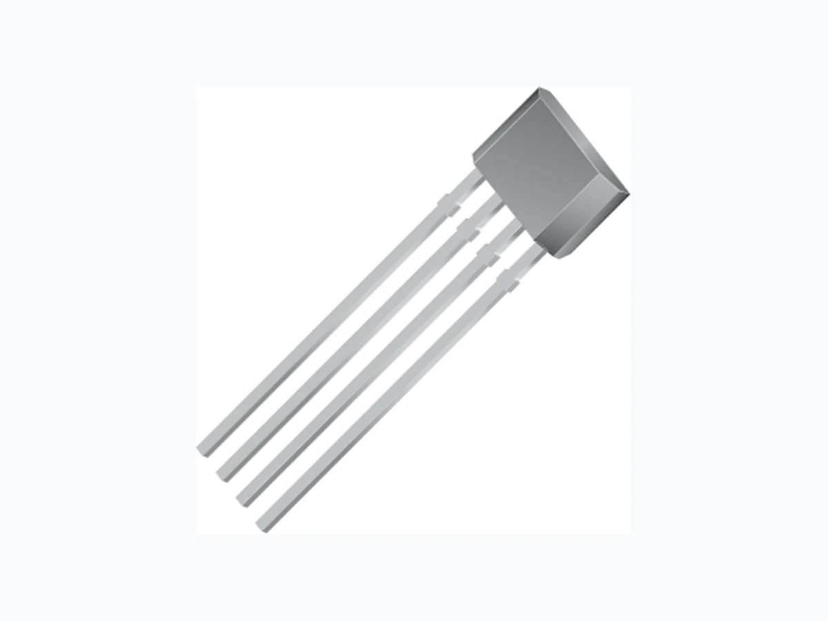
- High vibration immunity, in running mode (A1423 only) High Precision Hall Effect AC-Coupled Differential Sensor IC with Integrated Filter Capacitor Continued on the next page… Package: 4 pin SIP (suffix K) Functional Block Diagram Not to scale A1421, A1422, and A1423 Hall Amp Regulator Bandpass Filter Integrated Tracking Capacitor VOUT (Pin 2) VCC (Pin 1) GND (Pin 4) 0.1 uF VS+ Diagnostic Circuitry Gain Stage Dual Hall Transducers Comparator TEST (Pin 3) (Required) VREF
High Precision Hall Effect AC-Coupled Differential Sensor IC with Integrated Filter Capacitor A1421, A1422, and A1423 2Allegro MicroSystems, Inc.
115 Northeast Cutoff
Worcester, Massachusetts 01615-0036 U.S.A. Each device includes: a voltage regulator, two Hall transduc- ers, temperature compensating circuitry, a low-level ampli- fier, bandpass filter, Schmitt trigger, and an output driver. The on-board regulator permits operation with supply voltages from 4.0 to 26.5 V . The output stage can switch 20 mA over the full frequency response range of the device, and is compatible with CMOS logic circuits. The devices in this family differ from each other in their switchpoint specifications and their switching polarity. The A1421 has a small hysteresis and asymmetrical switchpoints, with one switchpoint at the zero-crossing. The A1422 has a small hysteresis and symmetrical switchpoints, both near the zero- crossing. The A1423 offers high vibration immunity, by means of its larger hysteresis that establishes symmetrical switchpoints Pin-out Diagram Absolute Maximum Ratings Characteristic Symbol Notes Rating Units Supply Voltage V CC Refer to Power Derating section 28 V Reverse Supply Voltage V RCC –18 V Output Current I OUT 25 mA Reverse-Output Current I ROUT –50 mA Operating Ambient Temperature T A Range L –40 to 150 ºC Maximum Junction Temperature T J(max) 165 ºC Storage Temperature T stg –65 to 170 ºC Terminal List Table Number Name
1 VCC
2 VOUT
3 TEST
4 GND
Description (continued) Product Selection Guide Part Number Output Switching at BDIFF = 0 Switchpoints Symmetry Packing* BDiff Increasing BDiff Decreasing BOP(typ) (G) BRP(typ) (G) BOP(max)+ BRP(min) (G) BOP(typ)+ BRP(typ) (G) BOP(min)+ BRP(max) (G) A1421LK-T Low (On) to High (Off) High (Off) to Low (On) 15 0 15 15 7.5 Bulk, 500 pieces/bagA1422LK-T High (Off) to Low (On) Low (On) to High (Off) 15 –15 0 0 0 A1423LK-T High (Off) to Low (On) Low (On) to High (Off) 65 –65 0 0 0 *Contact Allegro for additional packing options. 2 341 Continued on the next page…
High Precision Hall Effect AC-Coupled Differential Sensor IC with Integrated Filter Capacitor A1421, A1422, and A1423 3Allegro MicroSystems, Inc. Worcester, Massachusetts 01615-0036 U.S.A. further from the zero-crossing. The output polarities are shown in the Product Selection Guide table. This variety of options provides flexibility for achieving solu- tions for a wide range of applications, including automotive transmission and crankshaft speed sensing. The device package has an operating ambient temperature range –40°C to 150°C , and is provided in a 4-pin plastic SIP. Each package is available in a lead (Pb) free version (suffix, –T) , with a 100% matte tin plated leadframe. Description (continued) OPERATING CHARACTERISTICS Valid at TA = – 40ºC to 150ºC, TJ ≤ 165°C; over operational air gap range and VCC within operating range, unless otherwise noted. Typical operating parameters: VCC = 12 V and TA = 25°C. Characteristic Symbol Test Conditions Min. Typ. Max. Units
ELECTRICAL CHARACTERISTICS
CC Operating; TJ < TJ(max) 4.0 12 26.5 V Supply Current I CC – 4.2 7.0 mA Output Saturation Voltage V OUT(SAT) ISINK = 20 mA – 140 400 mV Output Leakage Current I OFF VOUT = 24 V, Bdiff = 0 – – 5 μA PROTECTION COMPONENT CHARACTERISTICS Reverse Supply Current I RCC VCC = –18 V – – –1 mA Supply Zener Current I ZSupply VS = 28 V – – 10 mA Supply Zener Clamp Voltage1 VZSupply ICC = 10 mA, TA = 25°C 28 33 37 V Output Zener Current I ZOutput VOUT = 28 V – – 3 mA Output Zener Clamp Voltage V ZOutput IOUT = 3 mA, TA = 25°C 28 – – V Output Short Circuit Current Limit I OUTS(lim) – – 50 mA RESPONSE CHARACTERISTICS Power-On State POS t < t Response – High – V Power-On Time2,6 tPO VCC > VCC(min) – 4.5 9 ms Settling Time3,6 tSettling fBdiff ≥ 100 Hz 0 – 50 ms Response Time6 tResponse Equal to tPO + tSettling; fBdiff ≥ 100 Hz 4.5 – 59 ms Upper Corner Frequency f CU –3 dB, single pole 20 – – kHz Lower Corner Frequency f CL –3 dB, single pole – – 20 Hz OUTPUT CHARACTERISTICS Output Rise Time 4 tr RPU = 1 kΩ, COUTC2 = 10 pF – – 200 ns Output Fall Time t f RPU = 1 kΩ, ISINK = 20 mA, COUTC2 = 10 pF – – 200 ns Continued on next page.
High Precision Hall Effect AC-Coupled Differential Sensor IC with Integrated Filter Capacitor A1421, A1422, and A1423 4Allegro MicroSystems, Inc. Worcester, Massachusetts 01615-0036 U.S.A. OPERATING CHARACTERISTICS, continued Valid at TA = – 40ºC to 150ºC, TJ ≤ 165°C; over operational air gap range and VCC within operating range, unless otherwise noted. Typical operating parameters: VCC = 12 V and TA = 25°C. Characteristic Symbol Test Conditions Min. Typ. Max. Units MAGNETIC CHARACTERISTICS5,6 Operate Point B OP 1421, Bdiff increasing, fBdiff = 200 Hz, Bdiff = 50 Gp-p VOUT switches from low (on) to high (off) 0.0 15.0 27.5 G 1422, Bdiff increasing, fBdiff = 200 Hz, Bdiff = 50 Gp-p VOUT switches from high (off) to low (on) 5.0 15.0 35.0 G 1423, Bdiff increasing, fBdiff = 200 Hz, Bdiff = 200 Gp-p VOUT switches from high (off) to low (on) 10.0 65.0 100.0 G Release Point B RP 1421, Bdiff decreasing, fBdiff = 200 Hz, Bdiff = 50 Gp-p VOUT switches from high (off) to low (on) –12.5 0.0 7.5 G 1422, Bdiff decreasing, fBdiff = 200 Hz, Bdiff = 50 Gp-p VOUT switches from low (on) to high (off) –35.0 –15.0 –5.0 G 1423, Bdiff decreasing, fBdiff = 200 Hz, Bdiff = 200 Gp-p VOUT switches from low (on) to high (off) –100 –65.0 –10.0 G Hysteresis B HYS 1421, fBdiff = 200 Hz, Bdiff = 50 Gp-p 5 15 35 G 1422, fBdiff = 200 Hz, Bdiff = 50 Gp-p – 30 – G 1423, fBdiff = 200 Hz, Bdiff = 200 Gp-p – 130 – G Applied Magnetic Field7 Bdiff Differential p-p magnetic field – – 1250 G 1ICC is equivalent to ICC(max) + 3 mA. 2Time required to initialize device. 3Time required for the output switchpoints to be within specifi cation. 4Output Rise Time will be dominated by the RC time constant. 5For lower frequencies, the absolute values of BOP, BRP, and BHYS may decrease due to delay induced by the high-pass fi lter. 6See Defi nitions of Terms section. 7Exceeding the maximum magnetic fi eld may result in compromised absolute accuracy.
High Precision Hall Effect AC-Coupled Differential Sensor IC with Integrated Filter Capacitor A1421, A1422, and A1423 5Allegro MicroSystems, Inc. Worcester, Massachusetts 01615-0036 U.S.A. THERMAL CHARACTERISTICS may require derating at maximum conditions, see application information Characteristic Symbol Test Conditions* Value Units Package Thermal Resistance RθJA Minimum-K PCB (single-sided with copper limited to solder pads) 177 ºC/W *In still air. Additional thermal information available on Allegro Web site. 20 40 60 80 100 120 140 160 180 Maximum Allowable VCC (V) (RQJA = 177 ºC/W) Minimum-K PCB VCC(min) VCC(max) 20 40 60 80 100 120 140 160 180 Temperature (°C) Power Dissipation, PD (mW) (R QJA = 177 ºC/W) Minimum-K PCB 100 150 200 250 300 350 400 450 500 550 600 650 700 750 800 850 900 The following provide additional information about some of the parameters cited. For additional information, visit the Allegro Web site at www.allegromicro.com. Applied Magnetic Field, B diff – The differential magnetic flux density, which is calculated as the arithmetic difference of the flux densities observed by each of the two Hall elements. fBdiff is the input signal frequency. Output Off Switchpoint (Operate Point), BOP – The value of increasing differential magnetic flux density at which the device output switches from low to high (A1421) or high to low (A1422 and A1423). Output On Switchpoint (Release Point), B RP – The value of decreasing differential magnetic flux density at which the device output switches from high to low (A1421) or from low to high (A1422 and A1423). Power-On Time, t PO – The time needed by the device, after power is applied, to initialize all circuitry necessary for proper operation. Settling Time, tSettling – The time required by the device, after tPO, and after a valid magnetic signal has been applied, to provide proper output transitions. Settling time is a function of magnetic offset, offset polarity, signal phase, signal frequency, and signal amplitude. Supply Current (on), I CC(on) – The current draw of the device with the output transitor is turned on. Supply Current (off), ICC(off) – The current draw of the device with the output transitor is turned off. Response Time, tResponse – The total time required for generating zero-crossing output transitions after initialization (the sum of Power-on Time and Settling Time). Defi nitions of Terms Power Derating Curve TJ(max) = 165°C; ICC = ICC(max) Maximum Power Dissipation TJ(max) = 165°C; ICC = ICC(max); VCC = VCC(max)
High Precision Hall Effect AC-Coupled Differential Sensor IC with Integrated Filter Capacitor A1421, A1422, and A1423 6Allegro MicroSystems, Inc. Worcester, Massachusetts 01615-0036 U.S.A. Empirical Results 4.5 20.0 12.0 VCC (V) 4.5 20.0 12.0 VCC (V) 4.5 20.0 12.0 VCC (V) 150 –40 TA (ºC) 150 –40 TA (ºC) 150 –40 TA (ºC) ICC(OFF) by TA Ambient Temperature, TA (ºC) Current (mA) 10.0 9.0 8.0 7.0 6.0 5.0 4.0 3.0 2.0 1.0 0.0 –50 0 50 100 150 200 Over V CC Range ICC(OFF) by VCC Supply Voltage, VCC (V) Current (mA) 10.0 9.0 8.0 7.0 6.0 5.0 4.0 3.0 2.0 1.0 0.0 0 5 10 15 20 25 Over T A Range ICC(ON) by VCC Supply Voltage, VCC (V) Current (mA) 10.0 9.0 8.0 7.0 6.0 5.0 4.0 3.0 2.0 1.0 0.0 0 5 10 15 20 25 Over T A Range Supply Voltage, VCC (V) 0 5 10 15 20 25 ICC(ON) by TA Ambient Temperature, TA (ºC) Current (mA) 10.0 9.0 8.0 7.0 6.0 5.0 4.0 3.0 2.0 1.0 0.0 –50 0 50 100 150 200 Over V CC Range VOUT(SAT) by TA Ambient Temperature, TA (ºC) Voltage (mV) 500 450 400 350 300 250 200 150 100 –50 0 50 100 150 200 Over V CC Range; ISINK = 20 mA VOUT(SAT) by VCC Voltage (mV) 500 450 400 350 300 250 200 150 100 Over T A Range; ISINK = 20 mA Continued on next page.
High Precision Hall Effect AC-Coupled Differential Sensor IC with Integrated Filter Capacitor A1421, A1422, and A1423 7Allegro MicroSystems, Inc. Worcester, Massachusetts 01615-0036 U.S.A. Simulation Results Continued on next page.
High Precision Hall Effect AC-Coupled Differential Sensor IC with Integrated Filter Capacitor A1421, A1422, and A1423 8Allegro MicroSystems, Inc. Worcester, Massachusetts 01615-0036 U.S.A. Simulation Results, continued Continued on next page.
High Precision Hall Effect AC-Coupled Differential Sensor IC with Integrated Filter Capacitor A1421, A1422, and A1423 9Allegro MicroSystems, Inc. Worcester, Massachusetts 01615-0036 U.S.A. Simulation Results, continued Continued on next page.
High Precision Hall Effect AC-Coupled Differential Sensor IC with Integrated Filter Capacitor A1421, A1422, and A1423 10Allegro MicroSystems, Inc. Worcester, Massachusetts 01615-0036 U.S.A. Simulation Results, continued
High Precision Hall Effect AC-Coupled Differential Sensor IC with Integrated Filter Capacitor A1421, A1422, and A1423 11Allegro MicroSystems, Inc. Worcester, Massachusetts 01615-0036 U.S.A. Device Evaluation: EMC Characterization Test Name Reference Speci fi cation ESD – Human Body Model* AEC-Q100-002 ESD – Machine Model AEC-Q100-003 Conducted Transients ISO 7637-1 Direct RF Injection ISO 11452-7 Bulk Current Injection ISO 11452-4 TEM Cell ISO 11452-3 *ESD test is done with no external components. Please contact Allegro MicroSystems for EMC performance information. Vs VCC TEST VOUTGND A1421, A1422 or A1423 Component Value Units R1* 1k Ω R2 100 Ω C1 0.1 μF C2 0.1 ηF *Pull-up resistor not required for protection but for normal operation. Recommended EMC test circuit. Test circuit recommended configuration may change after evaluation of first silicon.
12Allegro MicroSystems, Inc. Worcester, Massachusetts 01615-0036 U.S.A. operating temperature range. while decreasing (the negative direction). switching on noise or target jitter. PO, the output signal, VOUT, is high. settling time, tSettling, has also elapsed. Figure 1. Typical output characteristics with dual comparator operation. The example shown is for the A1421. Characteristics shown without delay, see characteristic data charts for delay and phase shift contributions.
1421 Output Signal, VOUT
1421 Switching State
13Allegro MicroSystems, Inc. Worcester, Massachusetts 01615-0036 U.S.A.
1422 Switching State
1423 Switching State
Figure 2. Comparative typical output characteristics. This chart illustrates the switchpoints and the output polarities of the A1421, A1422, and the A 1423. Characteristics shown without delay, see characteristic data charts for delay and phase shift contributions. remote-sensing environments. TEST, must be connected externally to the GND terminal.
4 VOUT
Figure 3. Basic application circuit. A pull-up resistor, RPU, is required
High Precision Hall Effect AC-Coupled Differential Sensor IC with Integrated Filter Capacitor A1421, A1422, and A1423 14Allegro MicroSystems, Inc. Worcester, Massachusetts 01615-0036 U.S.A. Power Derating The device must be operated below the maximum junction temperature of the device, TJ(max). Under certain combinations of peak conditions, reliable operation may require derating sup- plied power or improving the heat dissipation properties of the application. This section presents a procedure for correlating factors affecting operating T J. (Thermal data is also available on the Allegro MicroSystems Web site.) The Package Thermal Resistance, RJA, is a figure of merit sum- marizing the ability of the application and the device to dissipate heat from the junction (die), through all paths to the ambient air. Its primary component is the Effective Thermal Conductivity, K, of the printed circuit board, including adjacent devices and traces. Radiation from the die through the device case, R JC, is relatively small component of RJA. Ambient air temperature, TA, and air motion are significant external factors, damped by overmolding. The effect of varying power levels (Power Dissipation, PD), can be estimated. The following formulas represent the fundamental relationships used to estimate T J, at PD. PD = VIN × IIN (1) T J = TA + ΔT (3) For example, given common conditions such as: TA= 25°C, VCC = 12 V, ICC = 4.2 mA, and RJA = 177 °C/W, then: P D = VCC × ICC = 12 V × 4.2 mA = 50 mW T = PD × RJA = 50 mW × 177 °C/W = 9°C A worst-case estimate, PD(max), represents the maximum allow- able power level (VCC(max), ICC(max)), without exceeding TJ(max), at a selected RJA and TA. Example Reliability for VCC at TA = 150°C, package L-I1, using minimum- K PCB Observe the worst-case ratings for the device, specifically: RJA = 177°C/W, TJ(max) = 165°C, VCC(max) = 26.5 V , and ICC(max) = 7.0 mA. Calculate the maximum allowable power level, PD(max). First, invert equation 3: Tmax = TJ(max) – TA = 165 °C – 150 °C = 15 °C This provides the allowable increase to TJ resulting from internal power dissipation. Then, invert equation 2: PD(max) = Tmax ÷ RJA = 15°C ÷ 177 °C/W = 91 mW Finally, invert equation 1 with respect to voltage: VCC(est) = PD(max) ÷ ICC(max) = 91 mW ÷ 7.0 mA = 13 V The result indicates that, at TA, the application and device can dissipate adequate amounts of heat at voltages ≤VCC(est). Compare VCC(est) to VCC(max). If VCC(est) ≤ VCC(max), then reli- able operation between VCC(est) and VCC(max) requires enhanced RJA. If VCC(est) ≥ VCC(max), then operation between VCC(est) and VCC(max) is reliable under these conditions.
High Precision Hall Effect AC-Coupled Differential Sensor IC with Integrated Filter Capacitor A1421, A1422, and A1423 15Allegro MicroSystems, Inc. Worcester, Massachusetts 01615-0036 U.S.A. Package K, 4-pin SIP 24 31 E1 E2 2.20 1.50
0.84 REF
1.27 NOM
2.16 MAX 45° 45° D Active Area Depth, .0.42 mm Hall elements (E1 and E2); not to scale D E E E E B 1.29 Gate and tie bar burr area A B C Dambar removal protrusion (8X) A D For Reference Only; not for tooling use (reference DWG-9010) Dimensions in millimeters Dimensions exclusive of mold flash, gate burrs, and dambar protrusions Exact case and lead configuration at supplier discretion within limits shown Standard Branding Reference View N = Device part number Y = Last two digits of year of manufacture W = Week of manufacture Mold Ejector Pin Indent Branded Face YYWW NNNN 5.21 +0.08 –0.05 0.38 +0.06 –0.03 3.43 +0.08 –0.05 0.41 +0.07 –0.05 14.73 ±0.51 1.55 ±0.05 Branding scale and appearance at supplier discretion Copyright ©2004-2009, Allegro MicroSystems, Inc. The products described herein are manufactured under one or more of the following U.S. patents: 5,045,920; 5,264,783; 5,442,283; 5,389,889; 5,581,179; 5,517,112; 5,619,137; 5,621,319; 5,650,719; 5,686,894; 5,694,038; 5,729,130; 5,917,320; and other patents pending. Allegro MicroSystems, Inc. reserves the right to make, from time to time, such de par tures from the detail spec i fi ca tions as may be required to per- mit improvements in the per for mance, reliability, or manufacturability of its products. Before placing an order, the user is cautioned to verify that the information being relied upon is current. Allegro’s products are not to be used in life support devices or systems, if a failure of an Allegro product can reasonably be expected to cause the failure of that life support device or system, or to affect the safety or effectiveness of that device or system. The in for ma tion in clud ed herein is believed to be ac cu rate and reliable. How ev er, Allegro MicroSystems, Inc. assumes no re spon si bil i ty for its use; nor for any in fringe ment of patents or other rights of third parties which may result from its use. For the latest version of this document, visit our website: www.allegromicro.com